Reinforcement detailing of Columns from ETABS output
Reinforcement detailing of columns in Etabs 2018.
The ETABS file for a G+4 building is provided. Run the analysis and design the RCC Moment Resisting Frame. The following challenge deals specifically with two columns at the following grid intersections.
- 3A
- 3B
- Provide details of longitudinal reinforcement for the two columns, from foundation to terrace level. Sketch the column cross sectional & elevation details or draft it using AutoCAD software.
- Show shear reinforcement & lapping details as per special confining reinforcement provision of clause 8.1 of IS 13920 - 2016.
Ans:-
Aim:
- To provide Longitudinal reinforcement detail of two columns (3A and 3B) from foundation to terrace level.
- To provide Details of Transverse Reinforcement under Special Limited Reinforcement in Paragraph 8.1 of IS 13920-2016.
Introduction:
- A reinforced concrete column is a compressive load-bearing structural element composed of concrete with embedded reinforcing steel.
- For design purposes, columns are divided into two categories: short columns and thin columns.
- short column is a structural element whose relatively short length practically guarantees compression failure when a load is applied uniformly along its axis.
- Columns can be classified as short, medium, or long based on length, material properties, and other column lengths of the same design.
- The foundation of any structure begins with the design and analysis after marking the position of the columns.
- Thin columns can be tested in the laboratory to observe warping or the effects of warping.
- Columns based on variable coefficients are called long columns or short columns.
Procedure:
- Download and open the model given in challenge 7 in Etabs.
- Open the elevation view of the model.
- Check the model for errors and run the analysis.
- Start the designing process by selecting the ‘start design/check’ option.
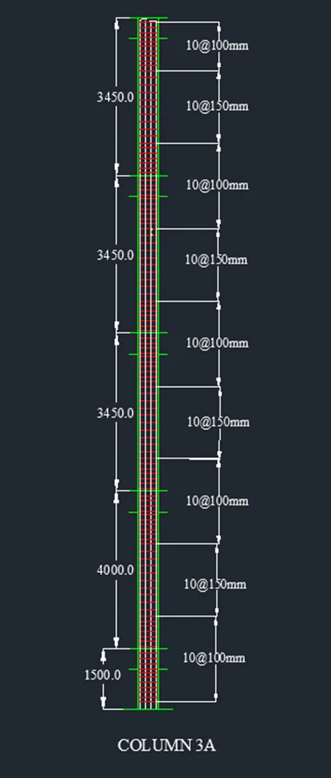
- After the software completes the process the longitudinal reinforcements are visible as shown.
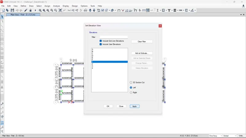
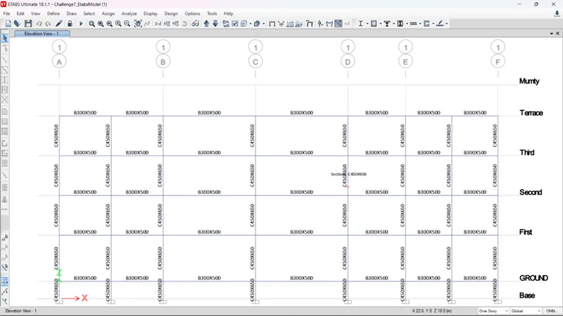
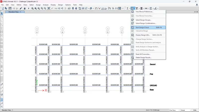
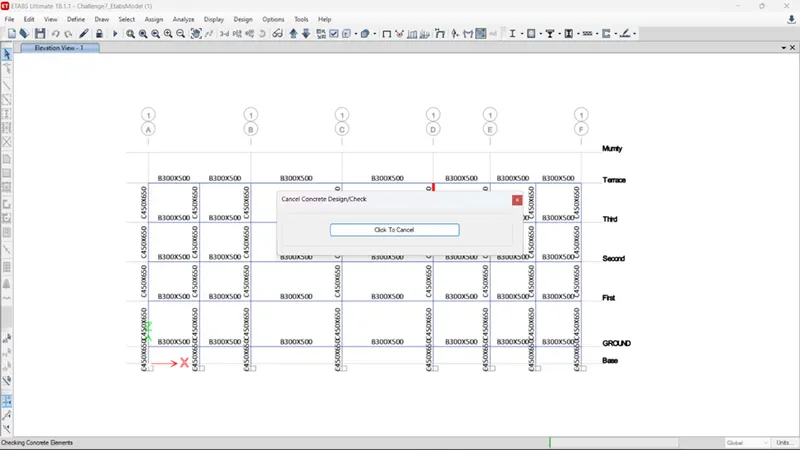
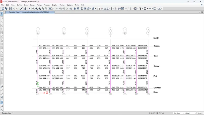
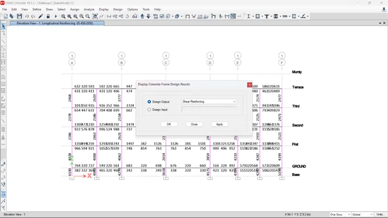
- Next you need to select Show project information option and then select Shear bar in project output and click OK button.
- Shear bar details are now displayed as shown below.
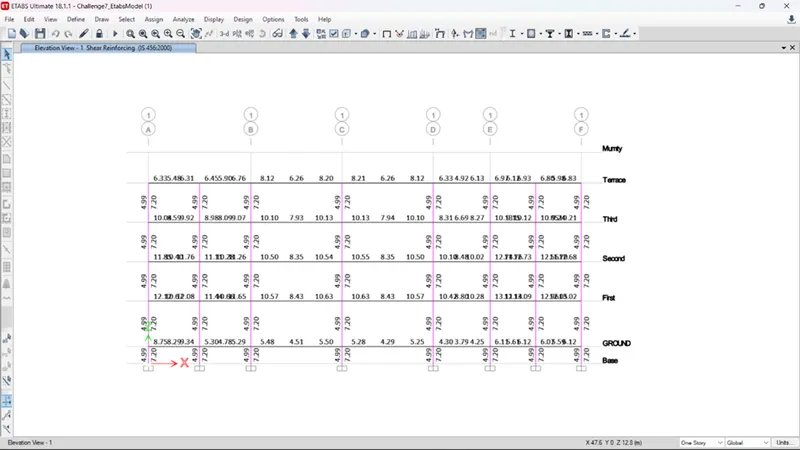
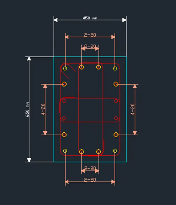
- Here, for column 7 (intersection 3A), we use a column size of 450 mm X 650 mm. The maximum value of Ast for column 7 is 7027mm2 which now gives 16 rods of 18 mm diameter (16-18Φ) as shown below.
- And provides a clamp size of 10mm, 100mm spacing for Area A and 150mm spacing for Area C as shown below.
- And the Details of transverse reinforcing bars are provided according to IS 13920-2016, Section 8.1, Regulations for special confining reinforcing bars.
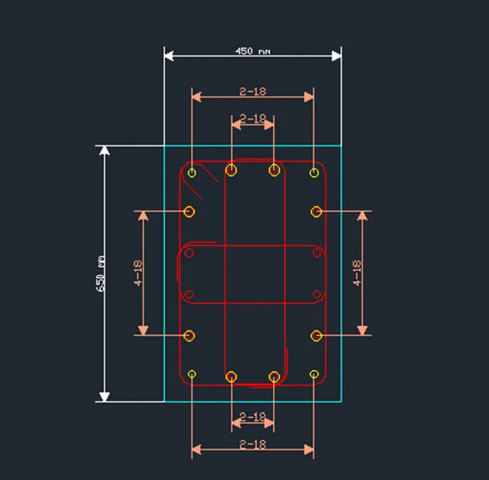
- Here, for column 8 (intersection 3B), we use column size 450 mm X 650 mm. The maximum value of Ast for column-8 is 5046mm2
- which now gives 16 rods of 20 mm diameter (16-20Φ) as shown below.
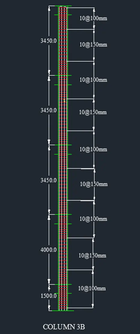
- and provides a clamp size of 10mm, 100mm spacing for Area A and 150mm spacing for Area C as shown below.
- And Details of transverse reinforcing bars are provided according to IS 13920-2016, Section 8.1, Regulations for special restricted reinforcing bars.
Result:
- Successfully provided the longitudinal reinforcement details of two columns (3A and 3B) from foundation to terrace height.
- The details of shear reinforcement are given according to IS 13920-2016, clause 8.1 special confining reinforcement which are as follows:
- For L0- not less than
- Larger column dimension-650mm
- 1/6th of clear span of column – 560mm
- 450mm
- For L0- not less than
So, adopt 650mm.
- Confinement spacing not more than:
- 1/4th of smaller column dimension- 113mm
- 6 times of dia of column main bar- 168mm
- 100mm
So, adopt 100mm
- AutoCAD software was also used to provide details of the column's section and height.