Creating a Floor plan, Footing detail and Isometric view using AutoCad
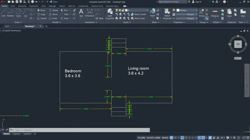
Aim: To draw a Line diagram of the floor plan of a two-bedroom building.
Introduction:
Line plan:
In this drawing, the position and size of internal rooms are given. Such a drawing is prepared with a single line. The thickness of the walls is not shown in it. Such drawing is prepared by some architect. Then the remaining drawing is prepared with the help of this drawing which is prepared by a draftsman.
Commands used:
- Line-Create a series of contiguous line segments. Each segment is a line object that can be edited separately.
- Rectangle- The rectangle command is used to create rectangles in our drawing. There are two methods to draw a rectangle. In the first method, we can create rectangles randomly by specifying the points. In the second method, we can create rectangles by specifying the value (length and width).
- Offset- The offset command in AutoCAD is used to create parallel lines, concentric circles, and parallel curves. We can offset any object through a point or at a specified distance. We can create as many parallel lines as possible and curves with the help of the offset command. The offset objects can also be modified further according to the requirements. Here, modification of offset object means that we can apply trim, extend, and other methods on it.
- Trim- The Trim command in AutoCAD is used to remove objects that meet other objects' edges. It is used to remove extra lines or extra parts of an object. We can also perform trim using different selection methods. We are required to select the portion of the object to trim.
Procedure:
Step :1 - Create a bedroom room (8.2x3.6) by a rectangle.
Step-2 Use the command "Explode" and select the rectangle.
- Draw an offset using the command "O".
- In the command line enter "O" and specify the distance of3.6 units from the left bottom end.
- Draw an offset using the command "O" at a distance of 4.2 units from the bottom right end.
Step-3 Extend the two lines at the bottom and in the top.
- Draw an offset at a distance of 0.3 between the two lines to the bottom side.
- Repeat the same step and create two offsets.
- Do the same process at the top.
- Trim the unwanted lines.
Step -4
- Using the line command draw a line at a distance of 3.2 units from the left bottom end to upwards of 0.9 units.
- Using the line command draw a line at a distance of 3.2 units from the left top end to downwards 1.8 units.
Result: The line diagram of the 2-bedroom building is drawn:
Aim: To draw footing detail.
Introduction:
Footing is an important part of foundation construction. They are typically made of concrete with rebar reinforcement that has been poured into an excavated trench. The purpose of footings is to support the foundation and prevent settling. Footing is especially important in areas with troublesome soil.
Commands used:
- Line-Create a series of contiguous line segments. Each segment is a line object that can be edited separately.
- Rectangle- The rectangle command is used to create rectangles in our drawing. There are two methods to draw a rectangle. In the first method, we can create rectangles randomly by specifying the points. In the second method, we can create rectangles by specifying the value (length and width).
- Offset- The offset command in AutoCAD is used to create parallel lines, concentric circles, and parallel curves. We can offset any object through a point or at a specified distance. We can create as many parallel lines as possible and curves with the help of the offset command. The offset objects can also be modified further according to the requirements. Here, modification of offset object means that we can apply trim, extend, and other methods on it.
- Trim- The Trim command in AutoCAD is used to remove objects that meet other objects' edges. It is used to remove extra lines or extra parts of an object. We can also perform trim using different selection methods. We are required to select the portion of the object to trim.
Procedure:
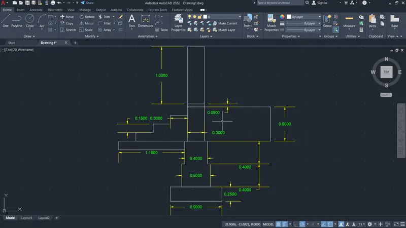
- i) Cross-section of load-bearing wall overspread footing
Step:1 - Create a rectangle by typing "REC" in the command box
- Specify the first corner point as (5,5)
- Specify the length of the rectangle =0.9 units in the command box
- Specify the width of the rectangle =0.25 units in the command box
Step:2- Create another rectangle -"REC" in the command box.
- Specify the first corner point which is 0.2 units from the starting point of the first rectangle.
- Enter the length of a rectangle as 0.5 units and the width of the rectangle as 0.4 units.
Step:3 - Create the third rectangle command- "REC"
- Specify the first corner point which is 0.05 units from the starting point of the second rectangle.
- Enter the length of the rectangle as 0.4 units and the width of the rectangle as 0.4 units.
Step 4 - A line is drawn from the corner of the third rectangle, command "L"
- Give the length as 1.15 units
- Move cursor downwards and give value 0.15 units and right and give length as 1.15 units.
Step:5 - Fourth rectangle is drawn, command -"REC"
- Specify the first corner point at a distance of 0.05 from the third rectangle
- Give the length as 0.3 and width as 0.6.
Step:6 - from the line drawn in step 4, at a distance of 0.3, draw another line with the distance of 0.15 units vertically and 0.3 units horizontally.
- Continue it two more times, until 3 steps are created.
Step:7-Draw another rectangle above the fourth rectangle, command -"REC".
- Specify the corner point as the corner of the fourth rectangle
- Click on dimension -give length as 0.3 units and width as 0.05 units.
step:8 - Drawn the fifth rectangle command ="REC"
- Specify the corner point as the corner of the fourth rectangular.
- Click on dimension -give length as 0.3 units and with as I unit.
- Erase the unwanted line by "trim"
Result: The cross-section of the load-bearing wall overspread footing is drawn.
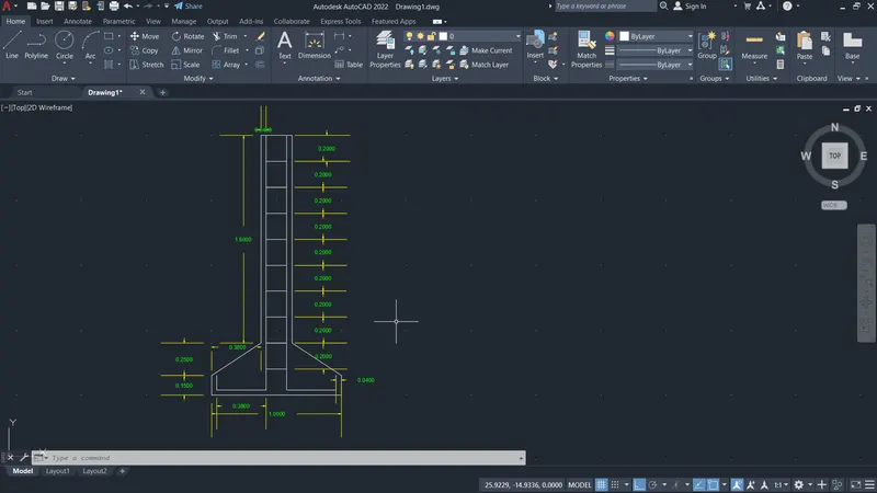
- ii) Cross-section of isolated footing:
Step1: - Draw a line with the command l and give 1 unit.
- give command "l" and give the relative coordinates as @ 0,0.15
- Give the next coordinate as @ 0.38,0.25.
- Next coordinate is given as @0,1.6 - Give @ 0.28,0
- Next coordinate @0, -1.6
- Next coordinate @0.38, -0.25
- Next @ 0, -0.15 or close.
Step:2 -Draw an offset with the command at a distance of 0.04 from the bottom line to upwards.
- Give the command of "o" select the object and give the offset distance as 0.04.
- Do the same at the right and left bottom end.
- Trim the unwanted lines.
Step:3 - Give an offset from the top line with an offset distance of 0.2 units.
- Give the command "o" and select the object
- give the offset distance as 0.2
- select multiple options a 9 such lines
- Trim the excess lines.
RESULT: C/s of isolated footing is drawn:
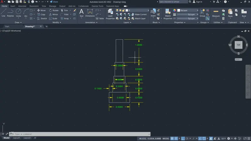
iii) Cross-section of a load-bearing wall with foundation details:
Step:1 - Create a rectangle by typing "REC" in the command box.
- Specify the first corner point as (5,5).
- Specify the length of the rectangle =0.9 units in the command box.
- Specify the width of the rectangle =0.45 units in the command box.
Step:2- Create another rectangle -"REC" in the command box.
- Specify the first corner point which is 0.15 units from the starting point of the first rectangle.
- Enter the length of the rectangle as 0.6 units and the width of the rectangle as 0.4 units.
Step:3 - Create the third rectangle command- "REC"
- Specify the first corner point which is 0.05 units from the starting point of the second rectangle.
- Enter the length of the rectangle as 0.5 units and the width of the rectangle as 0.3 units.
Step:4 - Create the Fourth rectangle command- "REC"
- Specify the first corner point which is 0.05 units from the starting point of the second rectangle.
- Enter the length of the rectangle as 0.4 units and the width of the rectangle as 0.6 units.
Step:5 - Drawn the fifth rectangle command -"REC"
- Specify the corner point as the corner of the fourth rectangular
- Click on dimension -give length as 0.3 units and with as 1 unit.
- Erase the unwanted line by "trim".
RESULT: The c/s of load-bearing wall foundation details are shown:
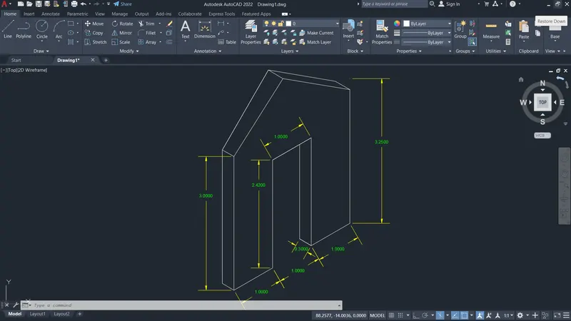
Aim: To draw an isometric view of steps and a gable wall.
Introduction:
Gable wall- A gable is the generally triangular portion of a wall between the edges of intersecting roof pitches. The shape of the gable and how it is detailed depends on the structural system used, which reflects climate, material availability, and aesthetic concerns. The term gable wall or gable end more commonly refers to the entire wall, including the gable and the wall below it.
Stairs- Stairs are a structure designed to bridge a considerable vertical distance by dividing it into smaller vertical distances, called steps. Stairs may be straight, or round, or may consist of two or more straight pieces connected at angles.
Isometric view- Isometric projection is a method for visually representing three-dimensional objects in two dimensions in technical and engineering drawings. It is an axonometric projection in which the three coordinate axes appear equally foreshortened and the angle between any two of them is 120 degrees.
Commands used-
- Line
- Isometric plane
Procedure:
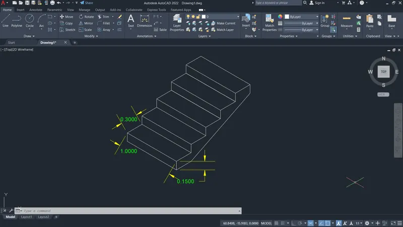
i) Isometric views of stairs:
- To work with an isometric view -command "ds" - snap off, grid off. Put isometric snap on.
- Make sure that ortho mode is on.
Step :1 - From isometric drafting select iso-plane left.
- Give command "l" and move the cursor to the -x direction(left) giving 1 unit.
- Moving the cursor to+ y-direction (top), gives 0.15 units.
- Moving the cursor to the + x direction again gives 1 unit and the cursor to the -y-direction(downwards) gives 0.15 units.
Step:2 - Change the isometric drafting to iso-plane top
- Move the cursor to the back and give 0.3 units from the last drawn point.
- Move the cursor to the right direction and give 1 unit.
- Move the cursor to the front and give 0.3 units.
Step:3 - Change the isometric drafting to iso-plane right
- Copy the object drawn, ortho off.
- Command "co" and specify the base point and place it to a new point.
- Repeat it until 4 steps are formed.
Step:4 - With iso-plane right join the two ends with ortho off.
Result: The steps are drawn in an isometric view.
ii) Isometric view of the gable wall.
- To work with an isometric view -command "ds" – snap off, grid off. put the isometric snap on
- Make sure that ortho mode is on
Step:1 - From isometric drafting select iso-plane left.
- Give command "l” and moving the cursor to right give 1 unit
- Pointing the cursor upwards gives 3 units
- Draw 0.3 units to left and 3 units downwards and 0.3 units to left.
Step:2 - Using isometric right, take line command and draw line upwards of 2.42 units from the starting point of step 1
- Draw 1 unit towards the right and 2.42 units downwards.
- Using isometric left again, using the line command draw 0.3 units to the left side and draw a line that intersects the top line.
Step 3 - Using iso-metric right with the line command draw 1.0 units to the right side and 3.0 units upwards.
Step:4 - By using the line command draw a line from the bottom left corner @1.5 units and extend the line 4 units upwards i.e., a total of 3.25 units from the bottom.
Step:5 - With the ortho off, draw a line between the corner of the left side and the projected line done in step 4.
- Draw it to the other side also till it meets the right corner.
Step:6 - Draw the vertical line with ortho on @0.3 and join the vertical line using lines from the left and right end same as in step 5 remove unwanted lines by using erase.
Result: The isometric view of the gable wall is drawn: