Reinforcement Detailing of Beams from ETABS output
Aim : To provide details of longitudinal and shear reinforcement for the two continuous beams.
To sketch the beam elevation details.
To evaluate reasons for failure of the middle span.
To calculate value of the maximum shear force in any one of the spans in both the continuous beams.
Introduction :
Capacity design introduces strong independence across various phases of detailed design of a building, in the same member as well as between different ones. The beams are the first members to be dimensioned in seismic design, in fact beam ends and the base section of walls are normally the only places whose detailed is based exclusively on analysis results in this case on their bending moments. The other designs are all based on the moment capacities of regions where plastic hinge formation is desired. Dimensioning of a column or a beam in shear depends on the longitudinal reinforcement of the column or beam itself and that of the members framing inti it at either end therefore it is carried out after the amount and layout of the beam and column longitudinal reinforcement have been determined.
Procedure :
- Open the downloaded file in etabs
- Check model and Run analysis
- Click on concrete frame design to design the frame
- Click on concrete frame design and select display design information
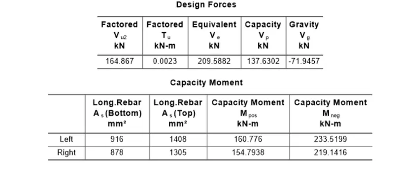
- Longitudinal reinforcement
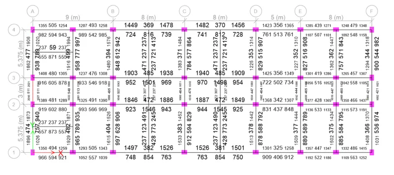
- Shear reinforcement
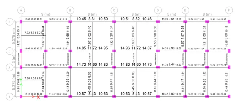
- Reinforcement details of 3 span of grid A is drawn in autocad
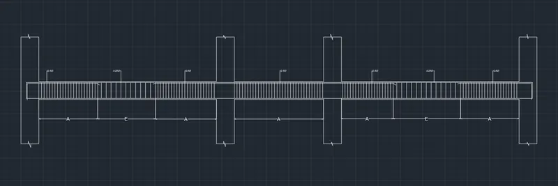
- Reinforcement details of 7 span of grid 3 is drawn in autocad

1. Provide reasons for failure of the middle span along grid A. What are the possible ways this issue can be resolved?
Steel provided higher than required, capacity moment increases. Since shear forces increased shear reinforcement also increases as per capacity design. Provided steel is higher than steel required, it will result in increase in shear demand. Thus beam is likely to fail, this what happened in the middle span of grid A which lead to failure.
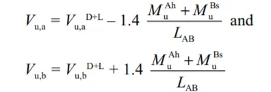
2. Calculate value of the maximum shear force in any one of the spans in both the continuous beams, as per clause 6.3.3 (b) in IS 13920 – 2016. Also, confirm these values from shear force demand calculated by ETABS.Please note that if longitudinal reinforcement provided is more than required (as per ETABS results), the shear force demand will vary from what is provided by ETABS.
As per clause 6.3.3(b) in IS 13920-2016
Sway right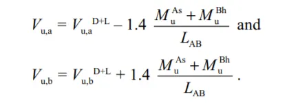
Sway Left
Grid A span 1
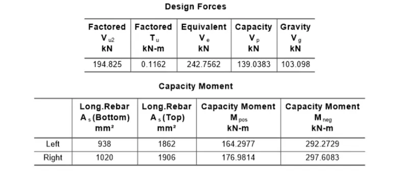
Grid 3 Span 1