Reinforcement Detailing of Beams from ETABS output
Aim:- To design the beams in detail from the ETABS 2019.
To provide details of longitudinal and shear reinforcement for the given two continuous beams.
To calculate the value of maximum shear force in any one of the spans in the continuous beams.
Introduction:-
- Beams are horizontal structural elements used for the supporting lateral loads.
- In conventional reinforced concrete structures, beams usually receive load from the floor slab, but may also be subjected to other loads such as wall loads, finishes, services installation, etc.
- The design and detailing of RC beams involves the selection of the proper beam size and the quantity of longitudinal and shear reinforcement that will satisfy ultimate and serviceability limit state requirements.
- Afterwards, It is very important that the beam reinforcements are placed and arranged properly on site, to avoid construction error.
Procedure:-
Step:-1
- First we have to open the challenge 7 page and download the challenge.
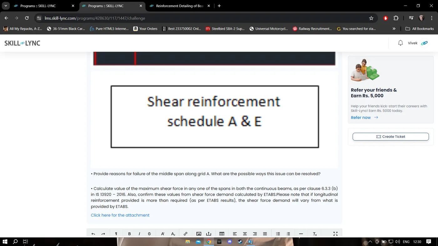
- After downloading the Challenge open it in the ETABS 2018, as shown below.
Step:-2
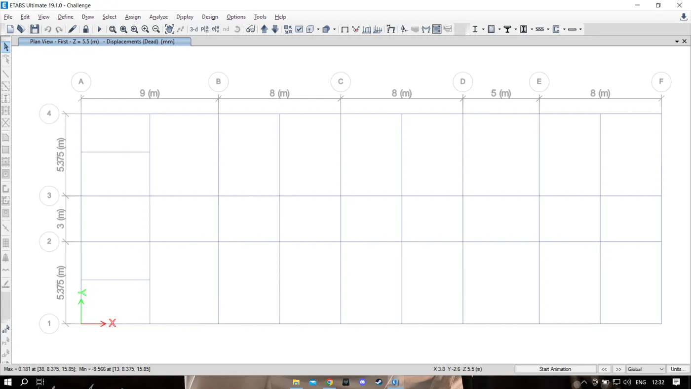
- We have to run Analysis on the model.
- Next we have to check the load combinations, as shown below
Step:-3
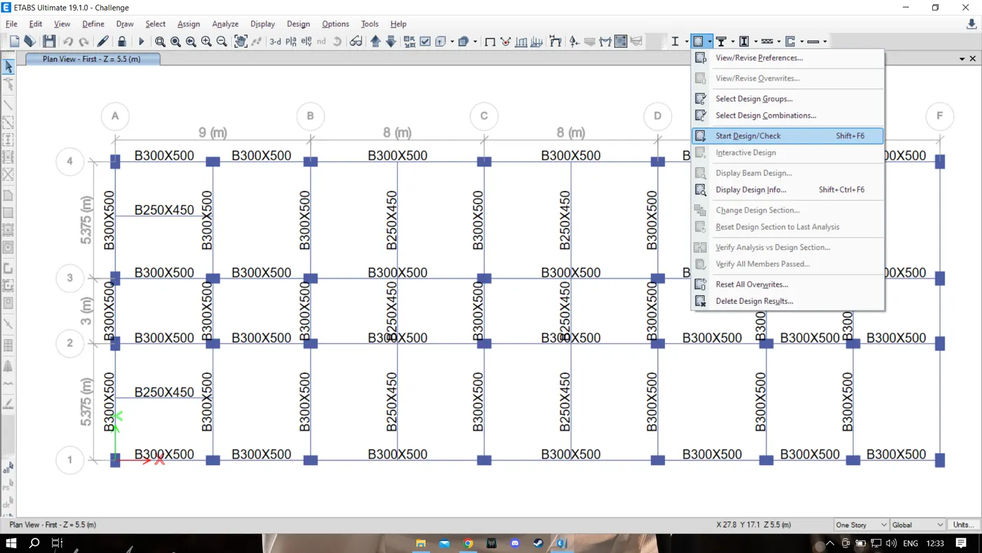
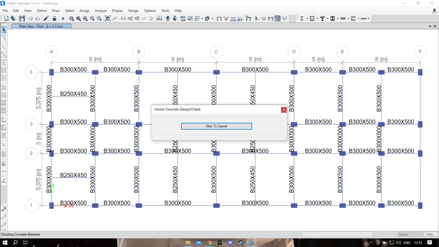
- Next we have to start the beam design by selecting the 'Start Design/Check' option, as shown below.
Step:-4
- After the completion of the beam design, we need to select the 'Display Design Info' option, as shown below.
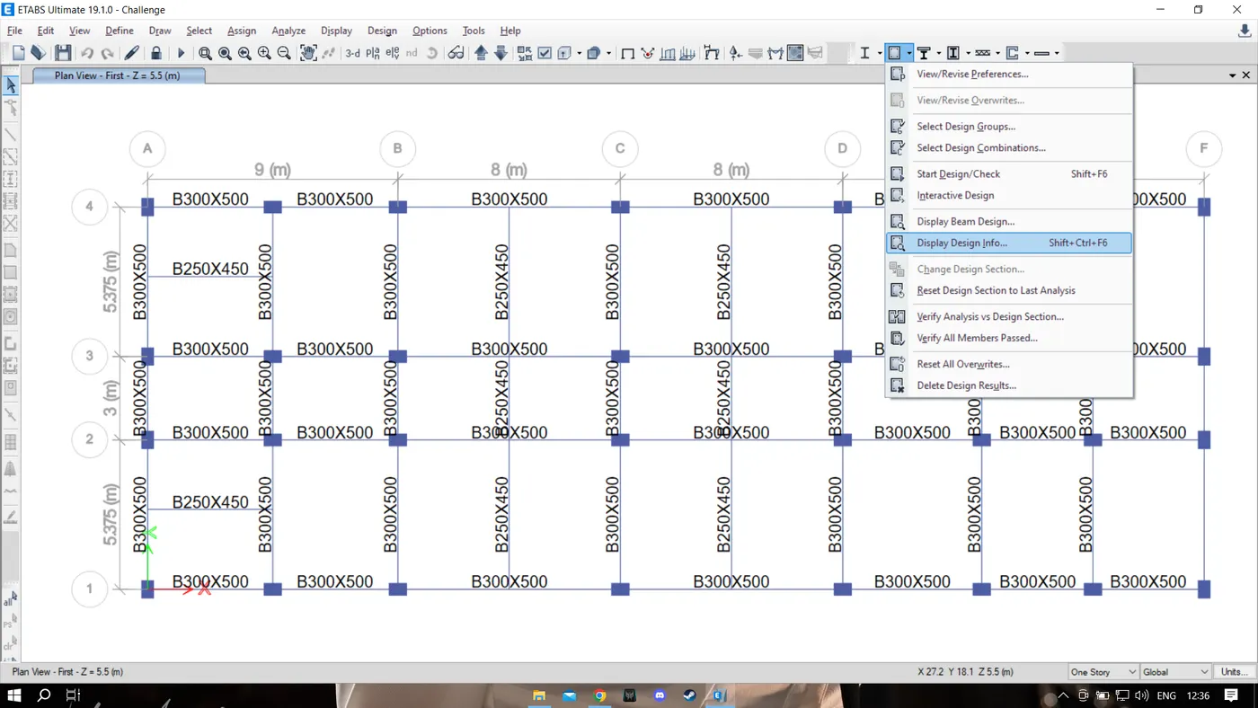
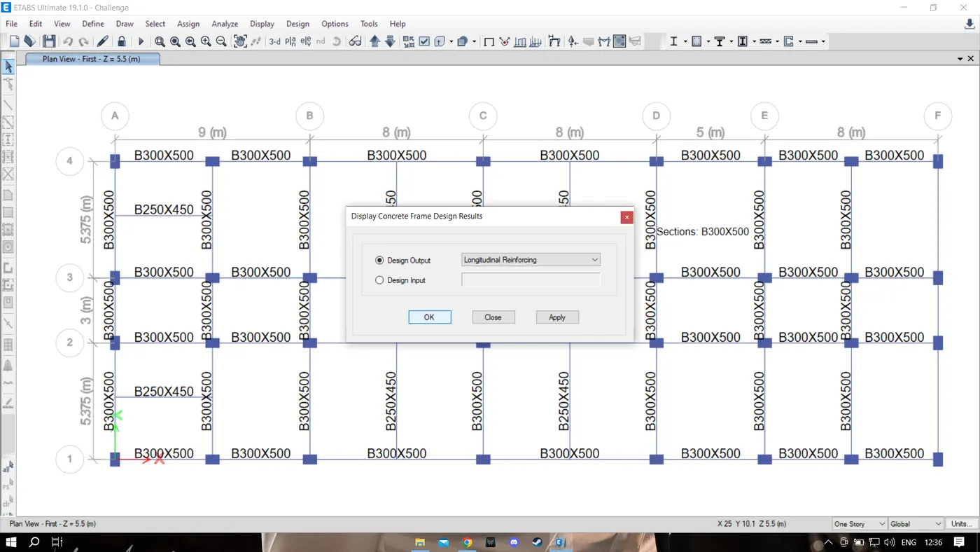
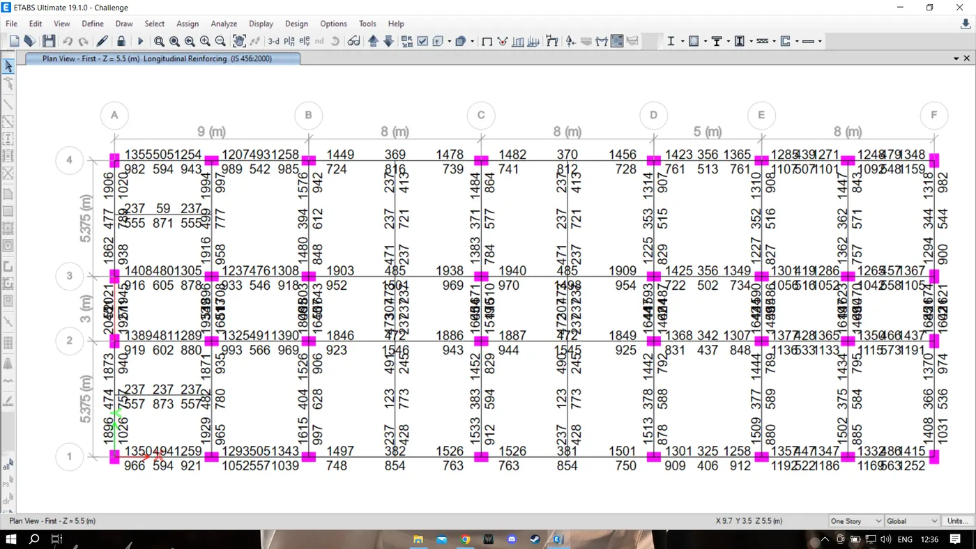
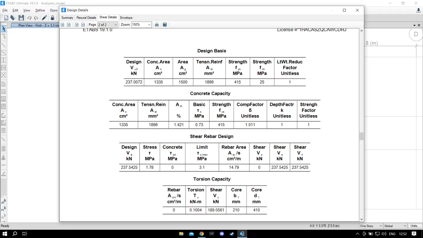
- To see the Design details of any one of the beams created in Shear reinforcement.
- Right click on any beam and we can see the Concrete beam design information Tab is opened.
- From there click Details to check the Designs of the shear details.
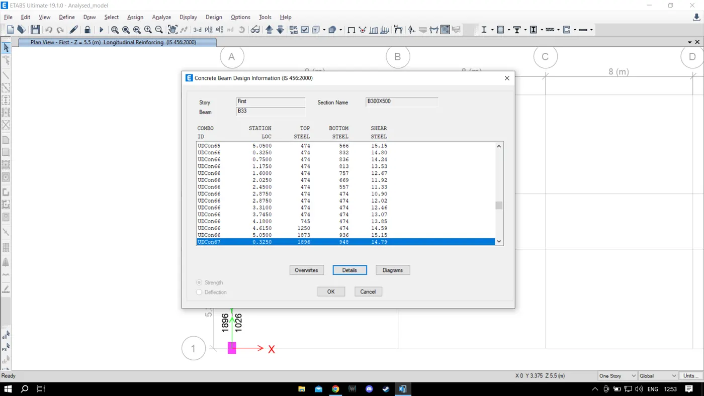
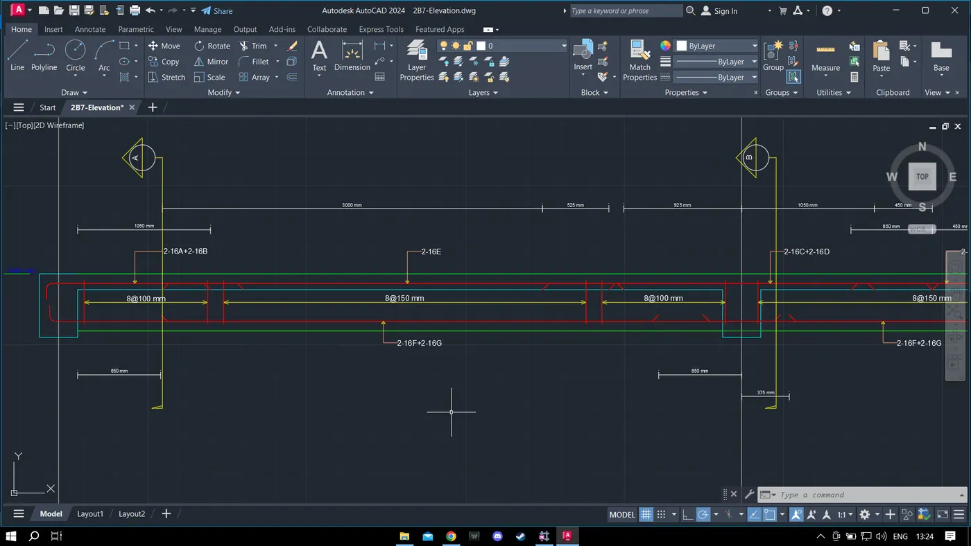
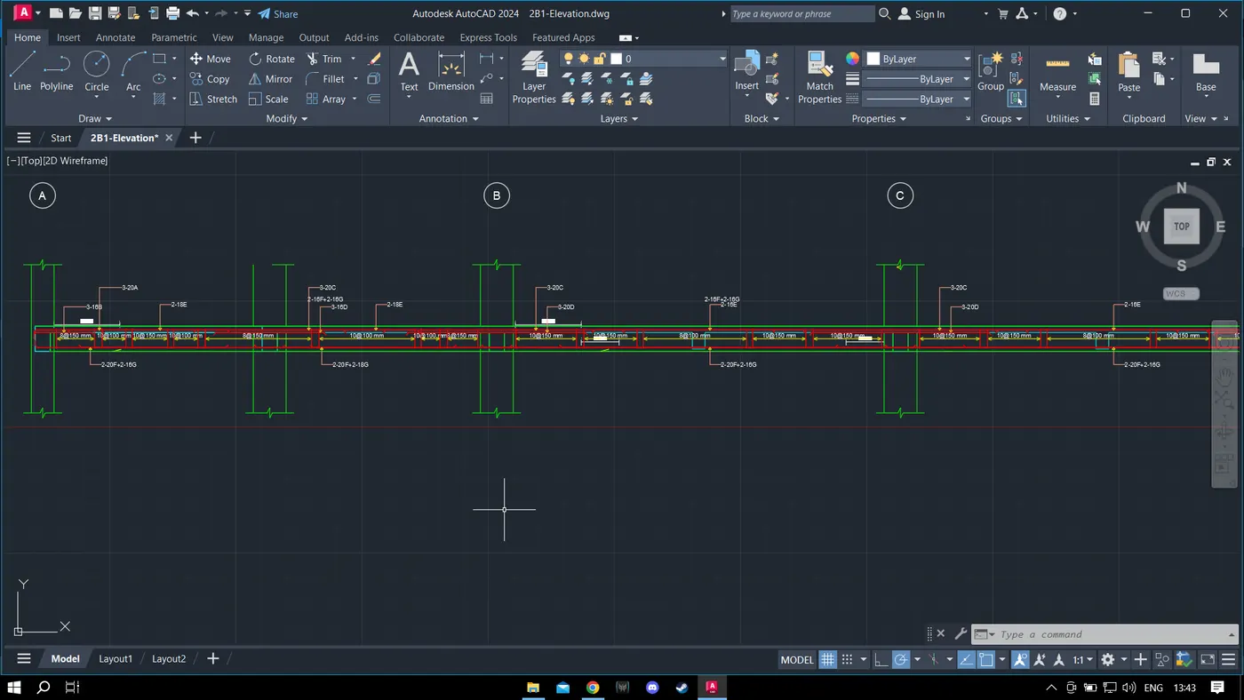
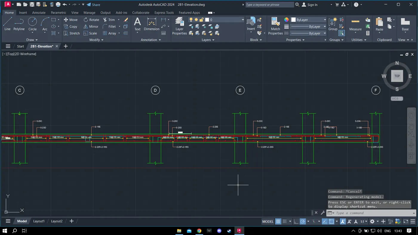
MID SPAN ALONG GRID A :
- The mid span along Grid A is failed due to it is Over stressed.
- It means it is violated the code values for shear reinforcement for shorter span beams
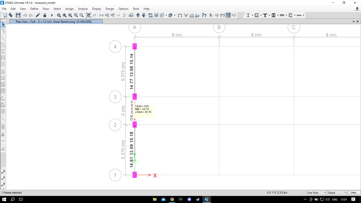
- Now right click on the Over stressed mid span to open the new tab named the concrete beam design information (IS 456 2000).
- In this opened tab we can see the shear steel was not calculated for 3 combinations .
- Then select and click the over stressed beam and click Details button to view the Details it.
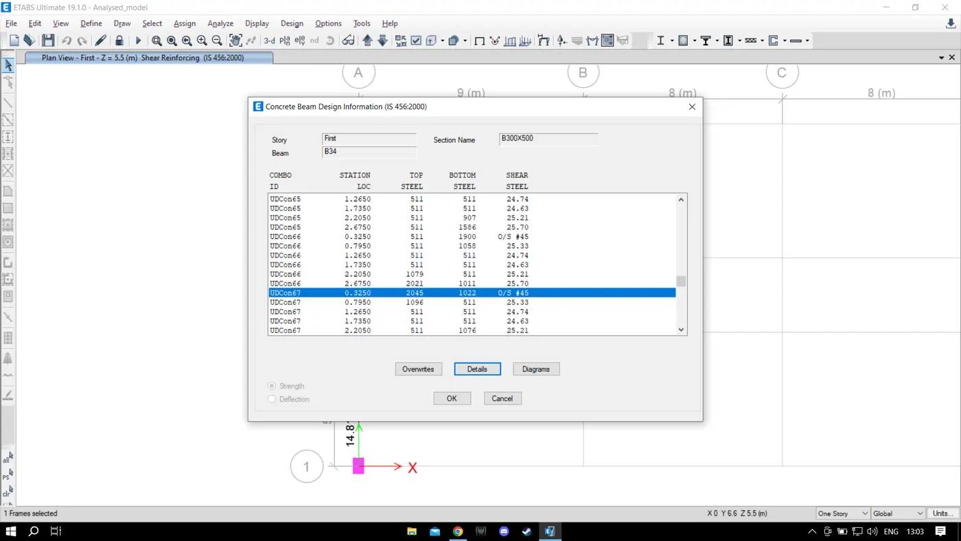
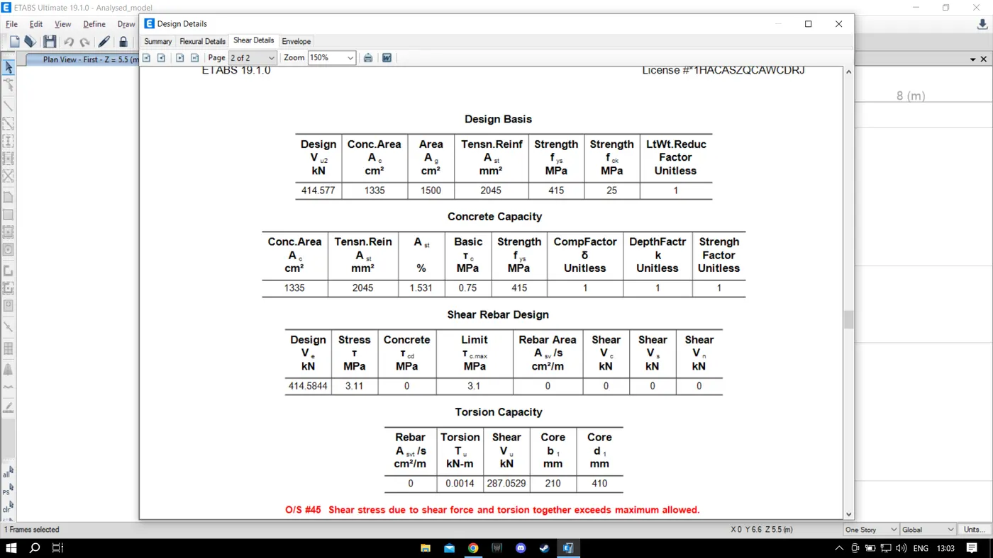
- From the Design Details tab we can see that it shows 'O/S #45 Shear stress due to shear force and torsion together exceeds maximum allowed '
- So we have to Reduce the loading or Increase the Area to get rid of these over stresses.
- The shear capacity of the concrete it varies with respect to the grade of concrete.
- Instead of the default M25 graded concrete used for the entire model we can use some higher grade for this beam alone like M30, M35, M40 etc.
- By this we can increase the shear capacity for the beam and therefore we can make it pass in the shear stress design
SWAY SHEAR FORCE TO RIGHT
i. Vua = Vua D+ L - 1.4 (MuAs + MuBh)/Lab
Given:
Mas = 174kNm
Mbh = 293kNm
Lab = 4.725m
Va+l = 92kN
Solution:
or
Vua = 92-1.4 (174+293)/4.725
Vua = 46kN
ii. Vua b = Vusb D+ L + 1.4 (MuAs + MuBh)/Lab
Mas = 174kNm
Mbh = 293kNm
Lab = 4.725m
Vd +1 = 92kN
Solution:
Vua = 92 + 1.4 (174 + 293)/4.725
Vua = 230kN
SWAY SHEAR FORCE TO LEFT :
Vua = Vua D+ L - 1.4 (MuAs + MuBh)/Lab
Given:
Mas = 234kNm
Mbh = 155kNm
Lab = 4.725m
Va+l = 70kN
Solution:
or
Vua = 70-1.4 (234+155)/4.725
Vua = 185kN
ii. Vua b = Vusb D+ L + 1.4 (MuAs + MuBh)/Lab
Mas = 234kNm
Mbh = 155kNm
Lab = 4.725m
Vd +1 = 70kN
Solution:
Vua = 70+1.4 (234+155)/4.725
Vua = 45kN
THE SWAY - SHEAR RESULT : Open Load Combination by clicking Define < Load Combination.
- Then Click existing load combination and select 'Add copy of combo'.
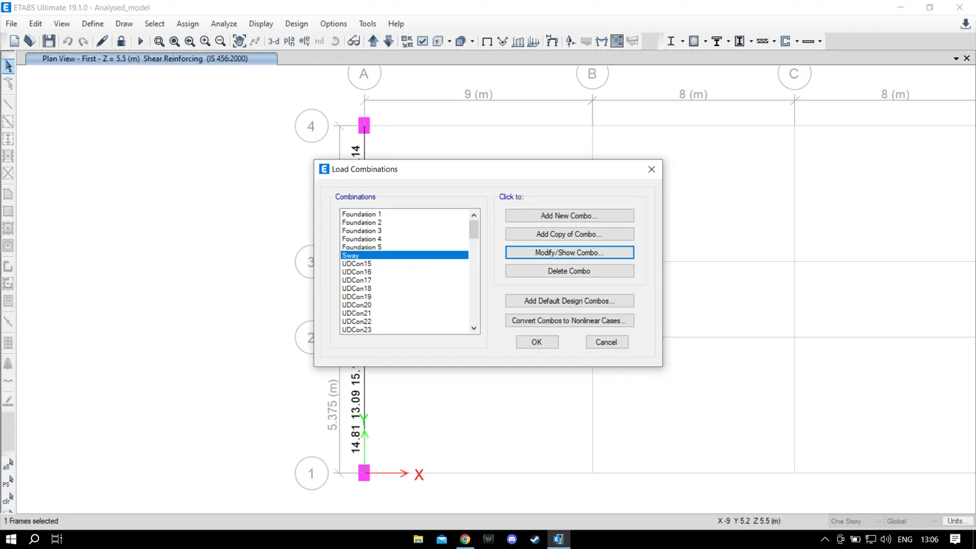
- Here we can see the opened Load Combination Data Tab.
- In this opened tab, change 'Load combination Name = Sway'.
- Now make scale factor for all the Loads as 1.2 and click OK.
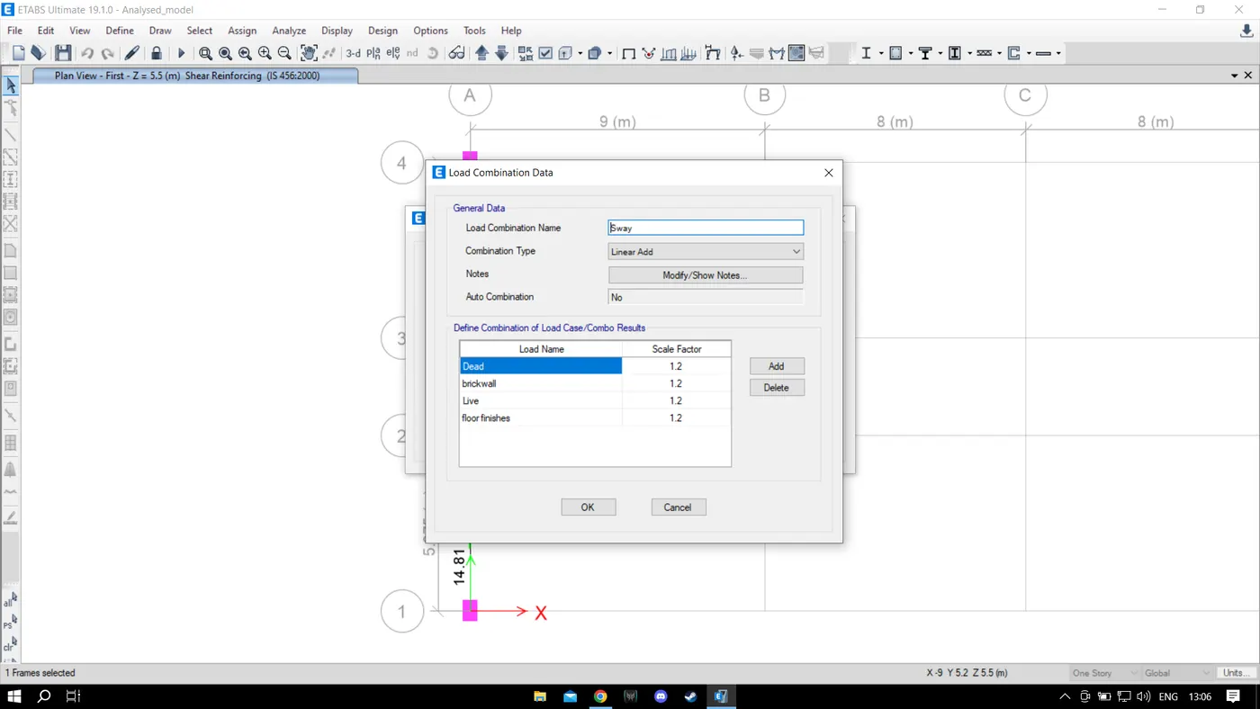
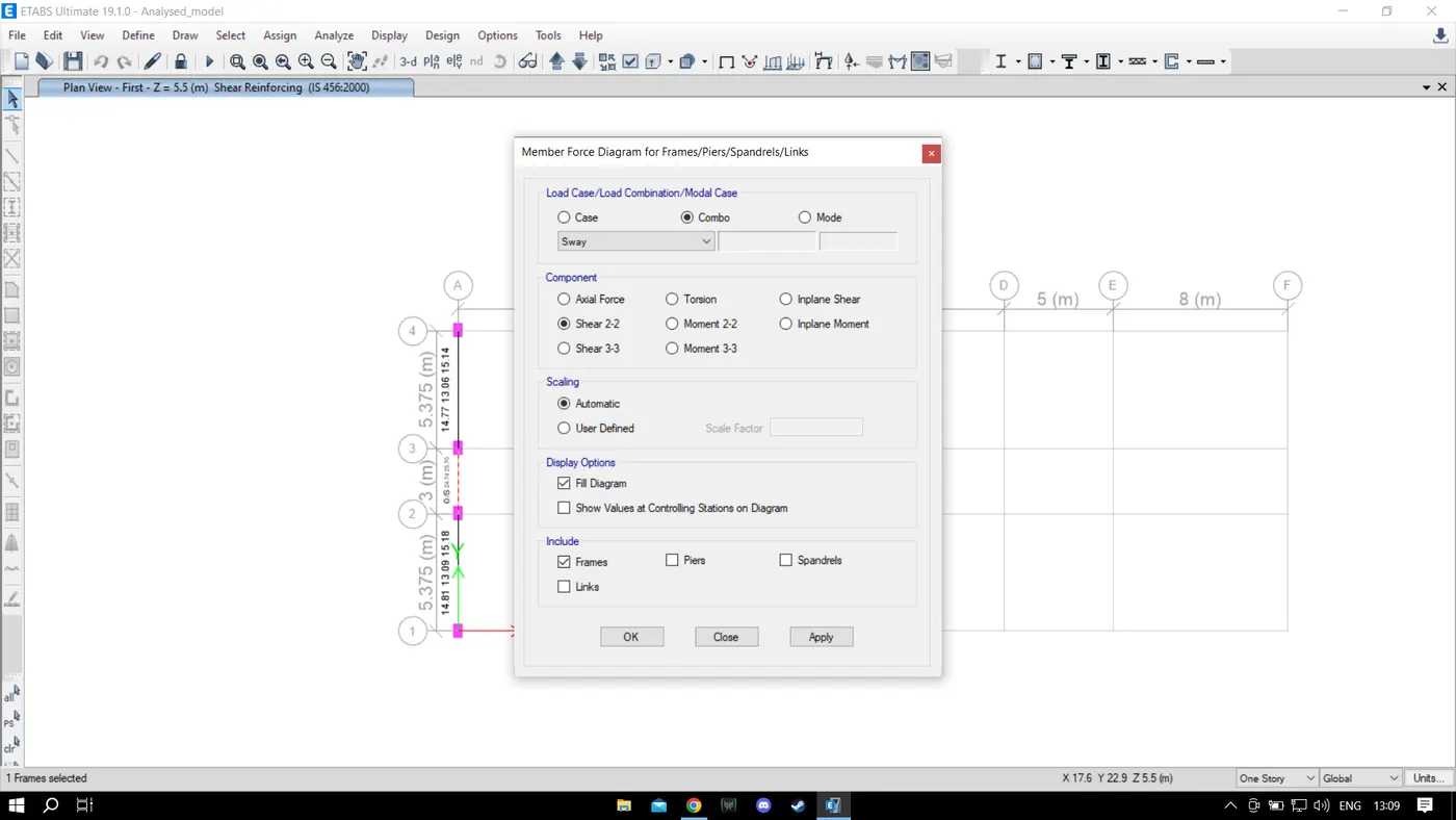
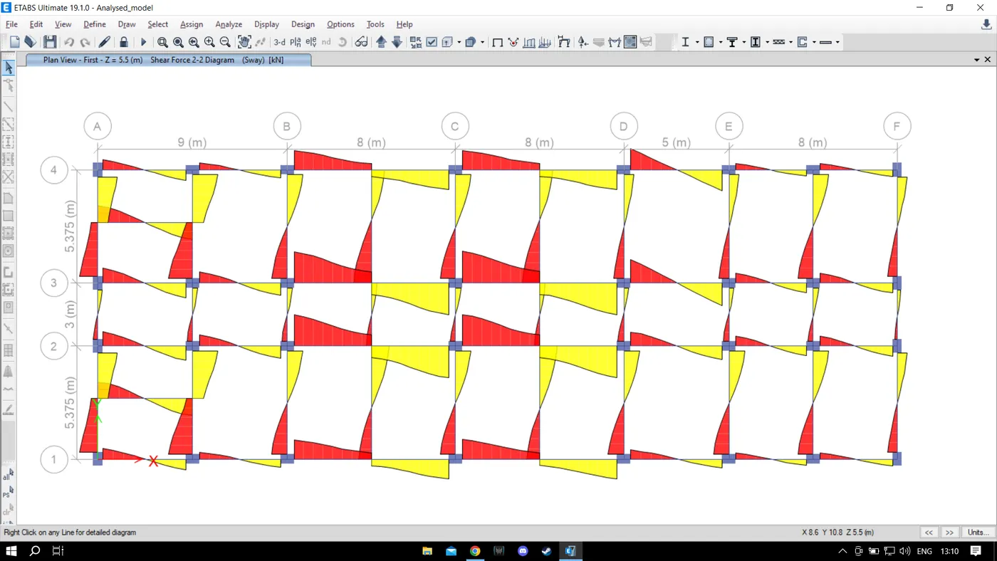
- At last to see the E-tabs calculation of shear force demand through Shear force Diagram.
- For that Click 'Display Frame' tool present at the Tool bar to open the 'Member Force Diagram Tab'.
- After the opening of the Tab click Combo < Shear 2-2 and select OK to see the E-tabs calculated sway values as shear diagram.
EXISTING SHEAR CAPACITY IN BEAM AS PER DRAWING (AS PER IS-456 2000 CLAUSE 40.4) :
Given :
Fy=415mm2
Solution :