Reinforcement Detailing of Beams from ETABS output
Challenge 7 – Detailed design of concrete buildings -1
Detail design of beams in E-Tabs 2018.
The ETABS file for a G+4 building is provided. Run the analysis and design the RCC Moment Resisting Frame. The following challenge deals specifically with two continuous beams in the 1st floor.
1) 3 span continuous beam along grid A
2) 7 span continuous beam along grid 3
Address the following issues thereafter.
• Provide details of longitudinal and shear reinforcement for the two continuous beams. Sketch the beam elevation details or draft it using autocad software. A sample of how beam elevation details is prepared in consultancy firms is provided below. Participants can prepare it as per their preference:
• Provide reasons for failure of the middle span along grid A. What are the possible ways this issue can be resolved?
• Calculate value of the maximum shear force in any one of the spans in both the continuous beams, as per clause 6.3.3 (b) in IS 13920 – 2016. Also, confirm these values from shear force demand calculated by E-TABS. Please note that if longitudinal reinforcement provided is more than required (as per ETABS results), the shear force demand will vary from what is provided by ETABS.
Ans:
Step-1: Download the model file and open it in E-tabs software.
Step-2: Check the model and analyze the model using Run analysis
Step-3: Once analysis completed click on Design and open Concrete frame design.
Step-4: In that click on concrete design/check.
Step-5: After checking is done, go to plan view
Step-6: On the plan view we have a column and beam detailing
Step-7: For this, Grid 3 and Grid A need to provide reinforcement details.
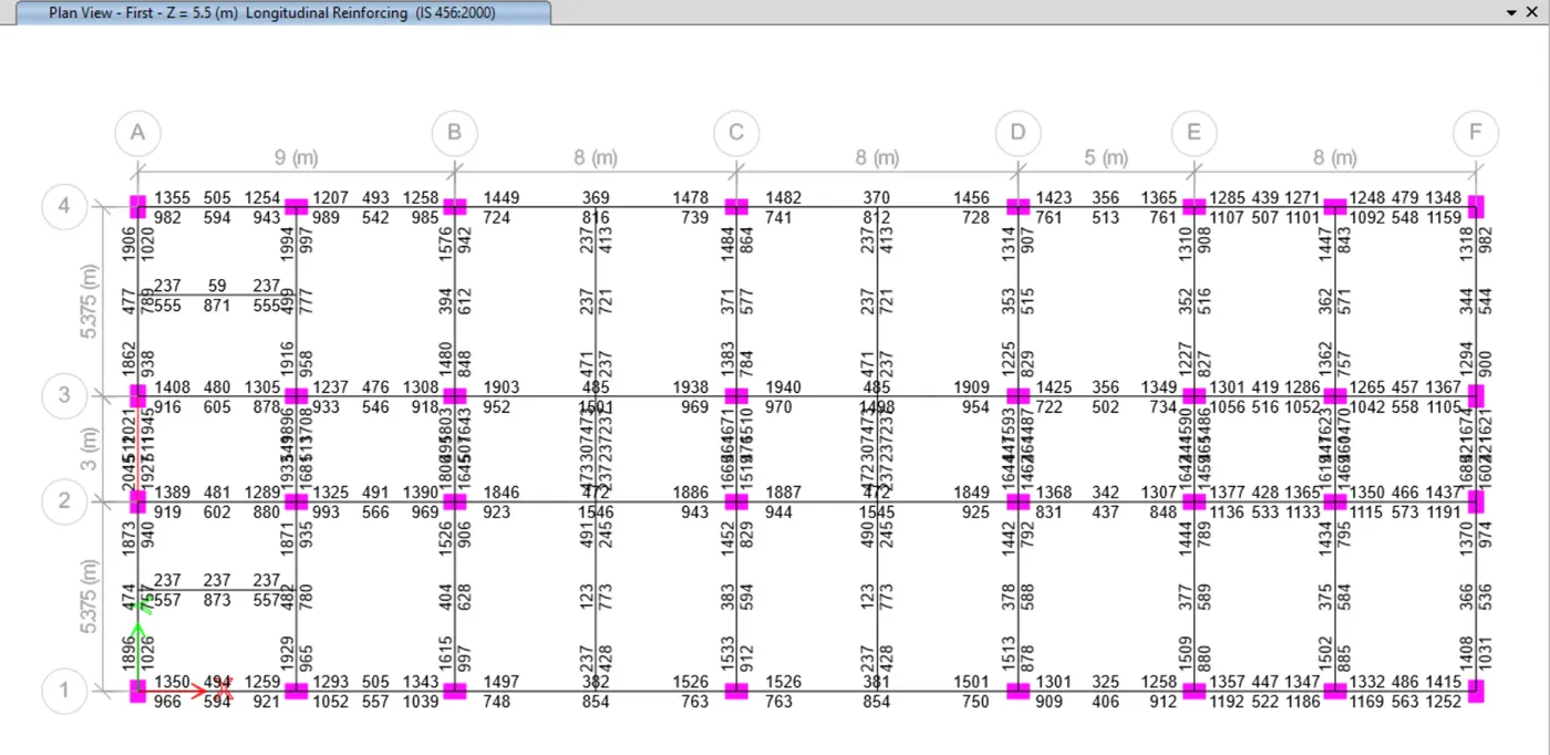
Step-8: [Grid-3]
At Top: Maximum Ast at Support = 194
Maximum Ast at Middle = 485.
2 dia of 32mm = 1606
1 dia of 25 mm = 490
Therefore, to satisfy the support we need to provide 2 dia of 32mm bar and additionally in the middle need to provide 1 dia of 25mm.
At Bottom: Maximum Ast at Support = 1056
Maximum Ast at Middle = 1501
3 dia of 25mm = 1470
1 dia of 16mm = 200.96
Therefore, to satisfy the support we need to provide 3 dia of 25mm bar and additionally in the middle need to provide 1 dia of 16mm.
Step-9: [Grid A]
At Top: Maximum Ast at Support = 2045
Maximum Ast at Middle = 477.
2 dia of 32mm = 1606
1 dia of 25 mm = 490
Therefore, to satisfy the support we need to provide 2 dia of 32mm bar and additionally need to provide 1 dia of 25mm.
At Bottom: Maximum Ast at Support = 1927
Maximum Ast at Middle = 789
2 dia of 32mm = 1606
1 dia of 16mm = 200.96
Therefore, to satisfy the support we need to provide 2 dia of 32mm bar and additionally in the middle need to provide 1 dia of 16mm.
Step-10: As per clause 6.3.3 the design force of equivalent Ve = 242.75 KN
Shear force under the linear analysis as per the load combination of UDCons66 = 194.825 KN