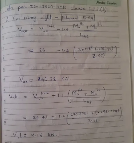
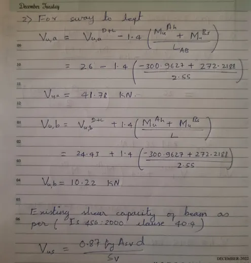
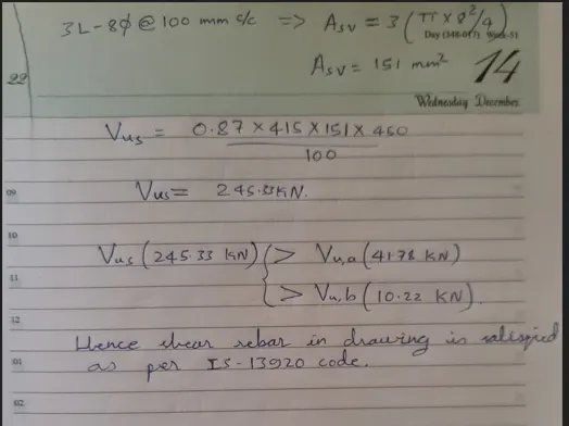
Reinforcement Detailing of Beams from ETABS output
Step 1: Download the given model of ETABS. Running the analysis. Once analysis is completed, running the Concrete Frame Design
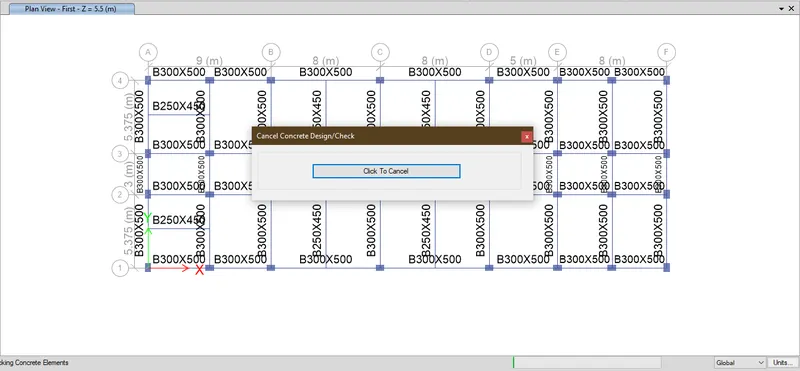
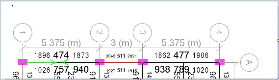
Step 2: The details of the Longitudinal reinforcement for the 1st floor is as below:
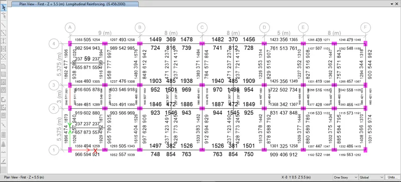
Here the area of longitudinal reinforcement is in mm^2.
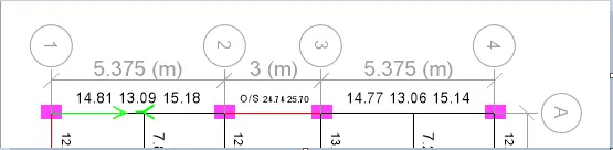
The details of the Shear reinforcement of 1st floor obtained from ETABS is as below:
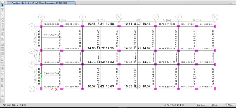
Here the area of shear reinforcement is in cm^2.
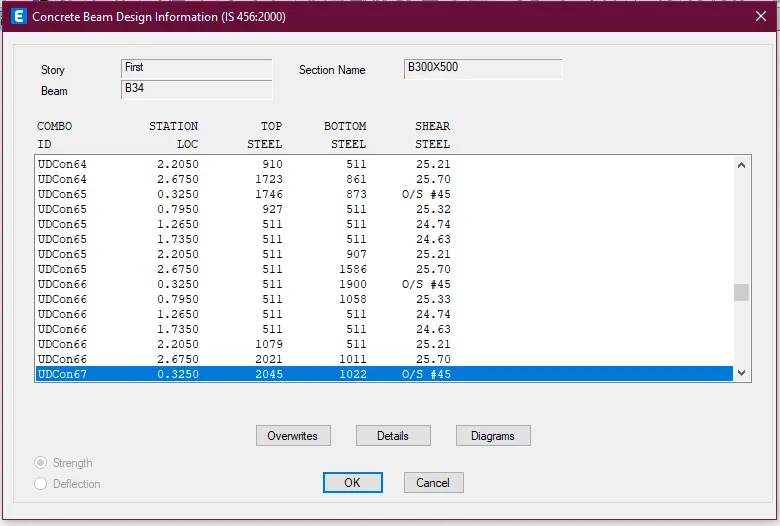
Refering the design details of the midspan beam along grid A, it can be observed that the shear stress has crossed allowable limit.
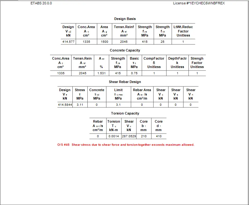
Shear stress is is the result of Load divided by Area of C/s at that point. Hence, the shear stress can be reduced by
1. Reducing the shear force
2. Increasing the area of cross section of concrete member
3. Using higher grade of concrete, as maximum shear stress increases with increase in grade of concrete. (Table 20 of IS 456: 2000)
Step 3:
Longitudinal reinforcement details of Beam along Grid - A from ETABS - Area of steel in mm^2
Shear reinforcement details of Beam along Grid - A from ETABS. Area of steel in cm^2/1000 mm
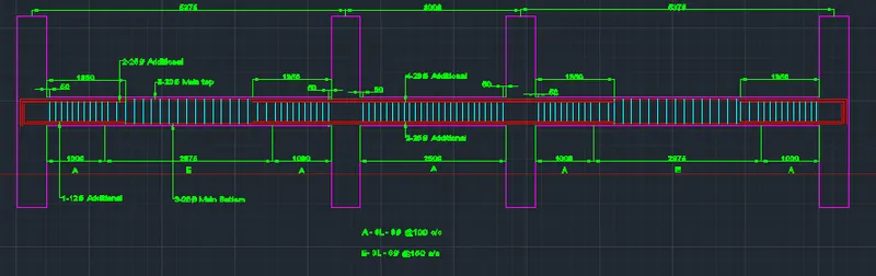
Reinforcement details from AutoCAD:
Longitudinal reinforcement details of Beam along Grid - 3 from ETABS - Area of steel in mm^2

Shear reinforcement details of Beam along Grid - 3 from ETABS. Area of steel in cm^2/1000 mm

Reinforcement details from AutoCAD: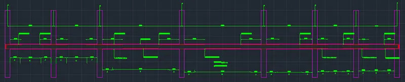
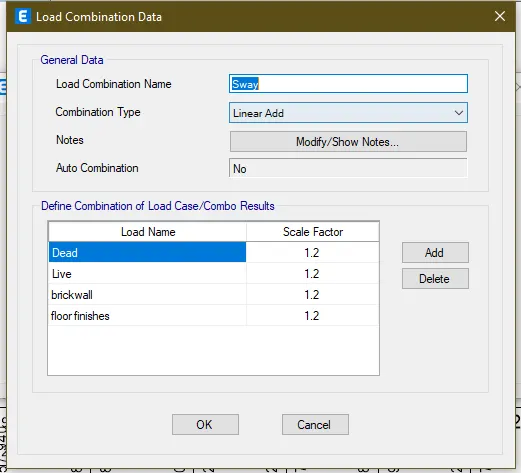
Step 4: Defining the new load combination Sway as below and rerunning the analysis & design.
Ccalculating the shear force for beam element B94 as below: