Reinforcement Detailing of Beams from ETABS output
CHALLENGE 8
AIM:- To run the analysis and design the RCC moment resisting frame for G+4 building and To provide details of longitudinal and shear reinforcement for the two continuous beams To sketch the elevation details or draft it using AutoCAD software. To provide reasons for failure of the middle span along Grid A and the possible ways to resolve the issue. To calculate value of the maximum shear force in any one of the spans in both the continuous beams, as per clause 6.3.3 (b) in IS 13920 – 2016. Also, confirm these values from shear force demand calculated by ETABS.
PROCEDURE:
1.Open the design in ETABS
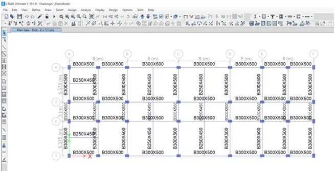
2.Go to analyze and check the model
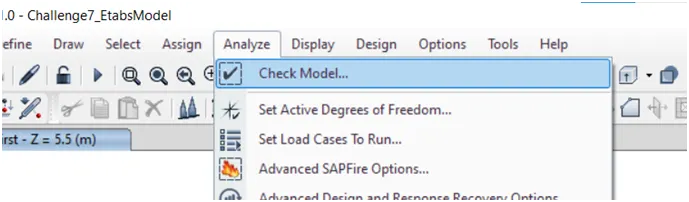
3.Ones model has checked
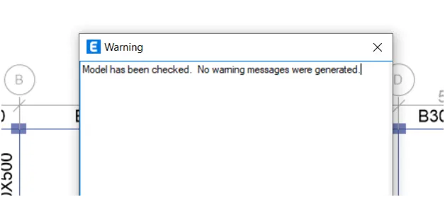
4.Than run analysis the model
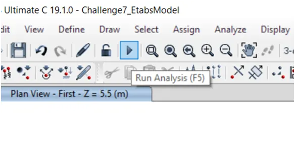
5.Check the animation of structure
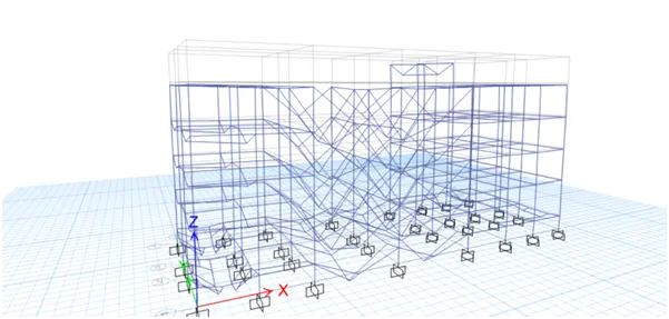
6.Click to concrete frame design preference and check the details than click ok
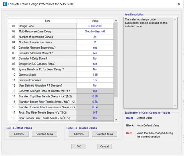
7.Than design the concrete frame
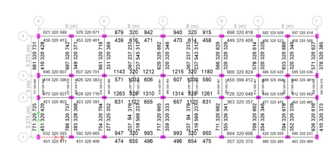
8.Show the longitudinal reinforcement
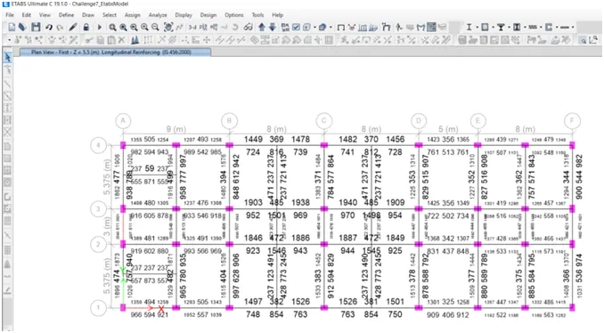
9.Go to display design Info
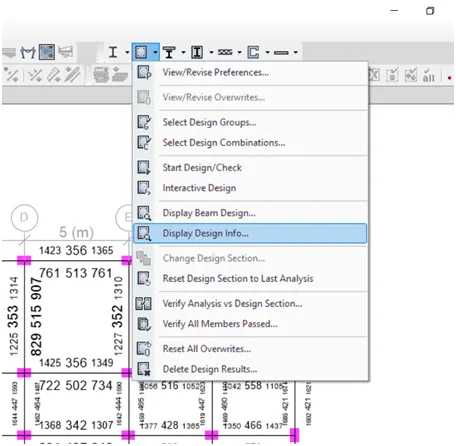
10.Choose the shear reinforcement than apply and ok
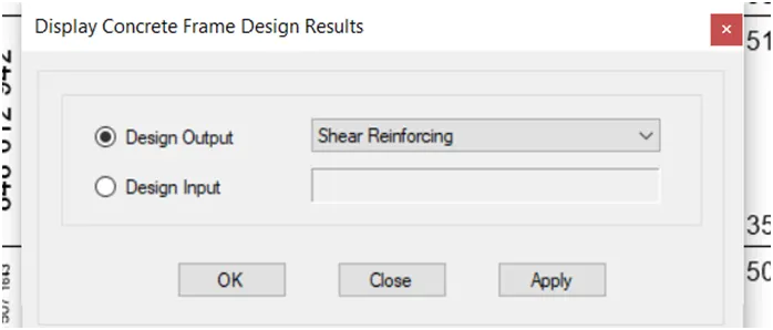
11.See the shear reinforcement detail
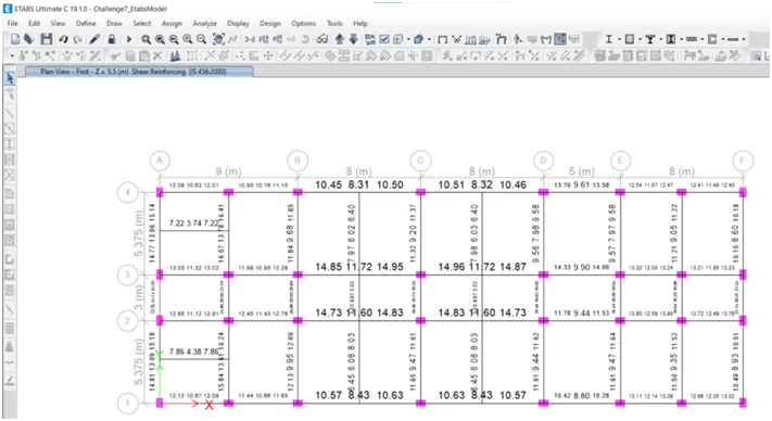
12.Go to the reinforcement calculation :
1.Longitudinal reinforcement calculation:
Ast for 32 diameter = 804 .24
Ast for 28 diameter = 615.75
Ast for 25 diameter = 490
Ast for 20 diameter= 314
Ast for 16 diameter = 201
Ast for 12 diameter = 113

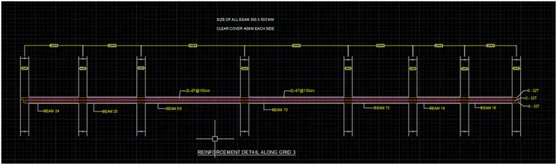
7 SPAN CONTINUOUS BEAM ALONG GRID 3
|
SL. NO |
BEAM LENGTH |
BEAM NUMBER |
LOAD COMBINATION |
STATION LOCATION |
TOP REINFORCEMENT (mm^2) |
BOTTOM REINFORCEMENT(mm^2) |
SHEAR STEEL (cm^2/m) |
|
1 |
4.5 |
B24 |
UDcon57 |
0.225 |
1408 |
704 |
13.05 |
|
2 |
4.5 |
B25 |
UDcon56 |
4.175 |
1308 |
654 |
120.5 |
|
3 |
8 |
B69 |
UDcon56 |
7.675 |
1938 |
969 |
140.45 |
|
4 |
8 |
B70 |
UDcon57 |
0.325 |
1940 |
970 |
14.45 |
|
5 |
5 |
B73 |
UDcon57 |
0.325 |
1425 |
713 |
13.67 |
|
6 |
4 |
B14 |
UDcon57 |
0.325 |
1301 |
650 |
13.15 |
|
7 |
4 |
B16 |
UDcon56 |
3.775 |
1367 |
684 |
13.08 |
Maximum at TOP reinforcement required 1938 mm^2
Maximum at BOTTOM reinforcement required 970 mm ^2
Maximum at the mid reinforcement required 1498 mm^2
Provided reinforcement at top 3T @32mm = 2412 mm^2
Provided reinforcement at bottom 3T @32mm = 2412 mm^2
Provided reinforcement at mid 2T @32mm = 1608.48mm^2
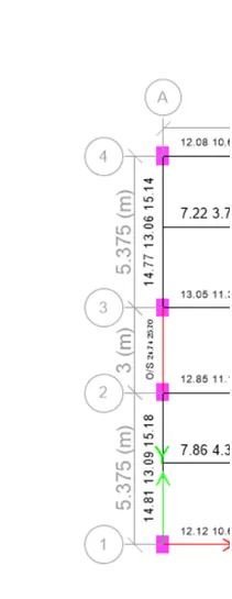
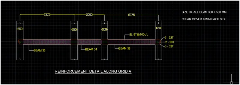
3 SPAN CONTINUOUS BEAM ALONG GRID A
|
SL. NO |
BEAM LENGTH |
BEAM NUMBER |
LOAD COMBINATION |
STATION LOCATION |
TOP REINFORCEMENT (mm^2) |
BOTTOM REINFORCEMENT(mm^2) |
SHEAR STEEL (cm^2/m) |
|
1 |
5.375 |
B33 |
UDcon67 |
0.325 |
1896 |
948 |
14.79 |
|
2 |
3 |
B34 |
UDcon67 |
0.325 |
2045 |
1022 |
O/S#45 |
|
3 |
5.375 |
B38 |
UDcon66 |
5.05 |
1906 |
953 |
15.12 |
Maximum at TOP reinforcement required 2045 mm^2
Maximum at BOTTOM reinforcement required 1022 mm ^2
Maximum at the mid reinforcement required 511 mm^2
Provided reinforcement at top 3T @32mm = 2412 mm^2
Provided reinforcement at bottom 3T @32mm = 2412 mm^2
Provided reinforcement at mid 2T @20mm = 628.31 mm^2
2.Shear reinforcement calculations
Grid line A (B38)
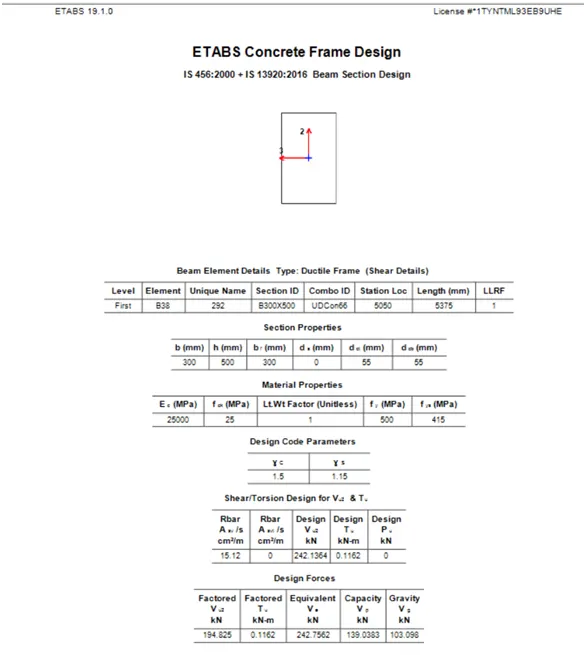
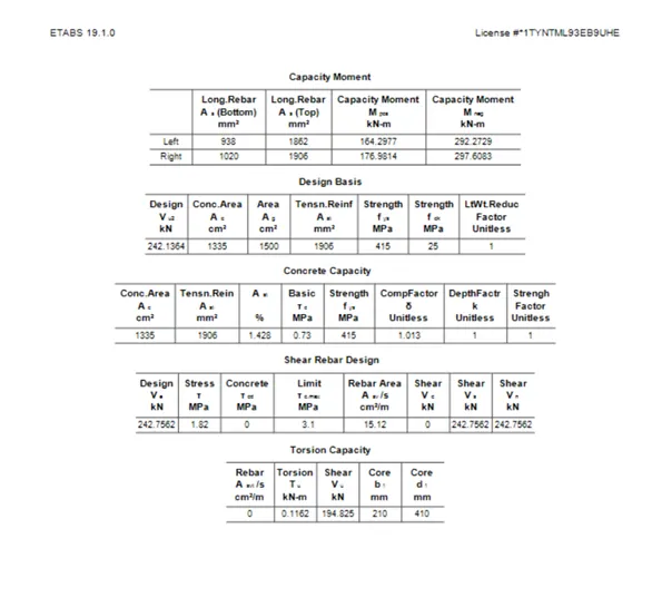
From ETABS output, Design shear force, V = 242.13 KN
Provide 2 legged 8 mm dia stirrups with 100 mm spacing
Providing 30 mm clear cover, Asv = 2x3.14/4x8^2 = 100 mm^2
Effective depth = 500-60 = 440 mm
Vus = 0.87*fy* Asv*d/Sv = 0.87*415*100*440/100 = 158.862 KN
Since Vus < V ( Design shear force), hence safe.
So provide 2 legged 8 mm dia stirrups with 100 mm spacing.
Grid line 3 (B 24)
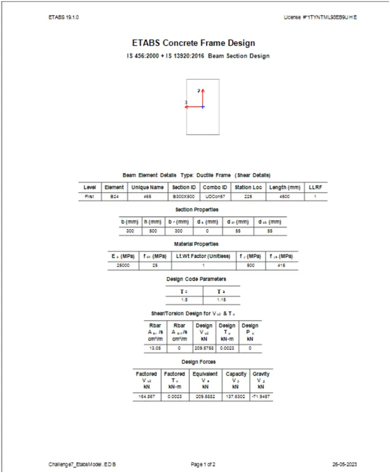
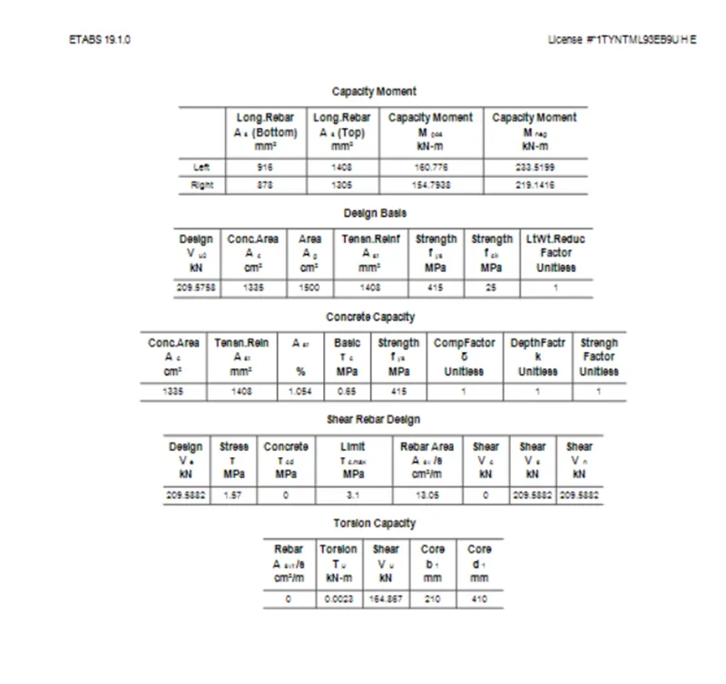
From ETABS Design shear force = 209.58 KN
Provide 2 legged 8 mm dia stirrups with 100 mm spacing
Providing 30 mm clear cover, Asv = 2*3.14/4*8^2 = 100 mm^2
Effective depth = 500-60 = 440 mm
Vus = 0.87*fy*Asv*d/Sv = 0.87*415*100*440/100 = 158.862 KN
Since Vus < V ( Design shear force), hence safe.
So provide 2 legged 8 mm dia stirrups with 100 mm spacing.
3.Reasons for failure of the middle span along grid 3
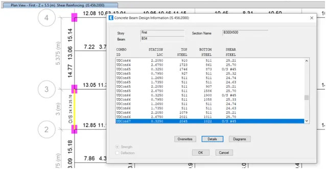
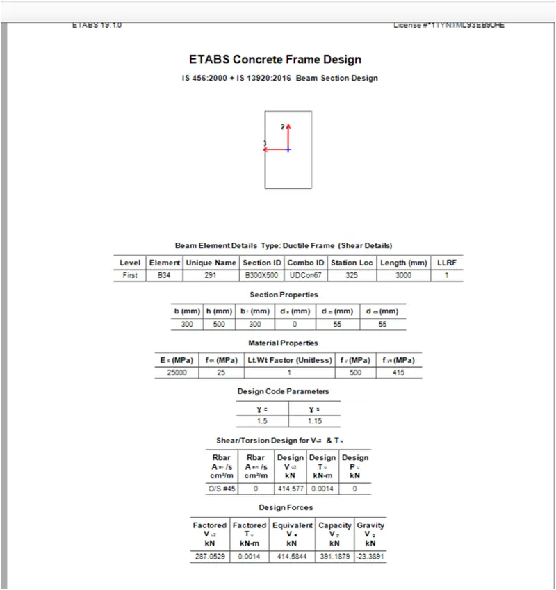
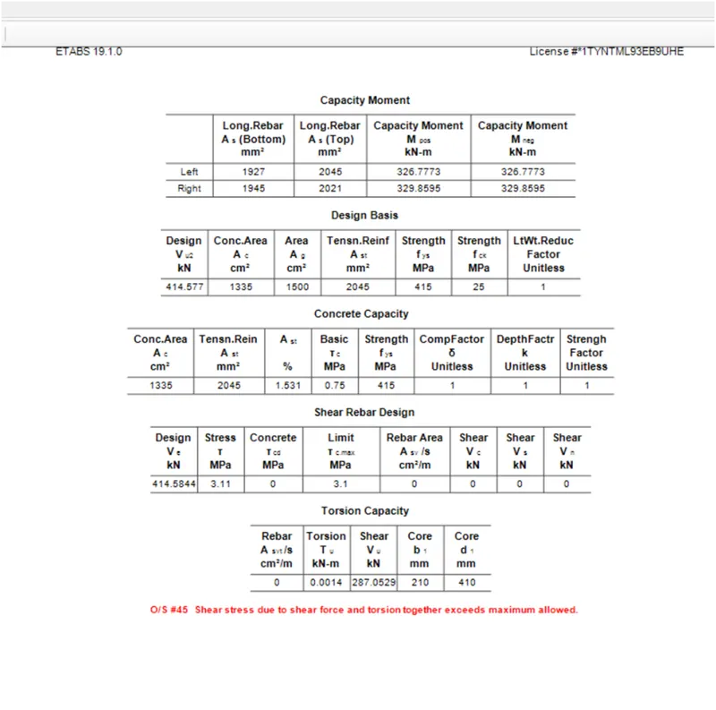
From the above ETABS output it has been shown that the limiting value of shear force and developed shear force remains the same. Hence it is not safe
The possible ways to solve this problem can be :-
- a) By providing higher grade of concrete
- b) By reducing effective depth
4.Calculate the value of maximum shear for
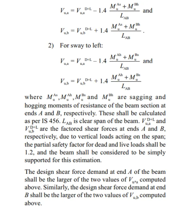
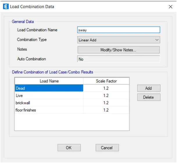
As per IS 13920-2016, new load combinations has been added for sway combination, the partial factor for dead and live load is considered to be 1.2
Sway to left:-
V(u+a) = 70.58 KN, Mu (As) = 160.776 KN and Mu (Bh) = 233.59 KN
Vu,a = 70.58 - 1.4*(160.774+233.54)/3.9 = -70.998 KN
Vu,a = 70.58 + 1.4*(160.774+233.59)/3.9 = 212.14 KN
Sway to right:-
V(u+a) = 70.58n KN, Mu (Ah) = 154.79 KN, Mu (Bs) = 219.14 KN
Vu,a = 70.58 - 1.4*(154.79+219.14)/3.9 = -54.06 KN
Vu,b = 70.58 + 1.4*(154.79+219.14)/3.9 = 195.22 KN
- Detailing of beams using AutoCAD
Grid A
Grid 3
RESULTS: The following has been illustrated properly along with results:-
- a) Analysis and design the RC moment frame for G+4 building
- b) Providing details of longitudinal and shear reinforcement for beam along with elevation details
- c) Providing reasons for failure of the middle span along grid A
- d) Calculating value of maximum shear forces in any of the span