Creating a Floor plan, Footing detail and Isometric view using AutoCad
C.S. OF LOAD BEARING WALL OVER SPREAD FOOTING
AIM: To create a footing diagram in auto cad and learn about footing and detailing. Know about auto cad how to work.
PROCIDURE:
1.Open auto cad and set drawing units
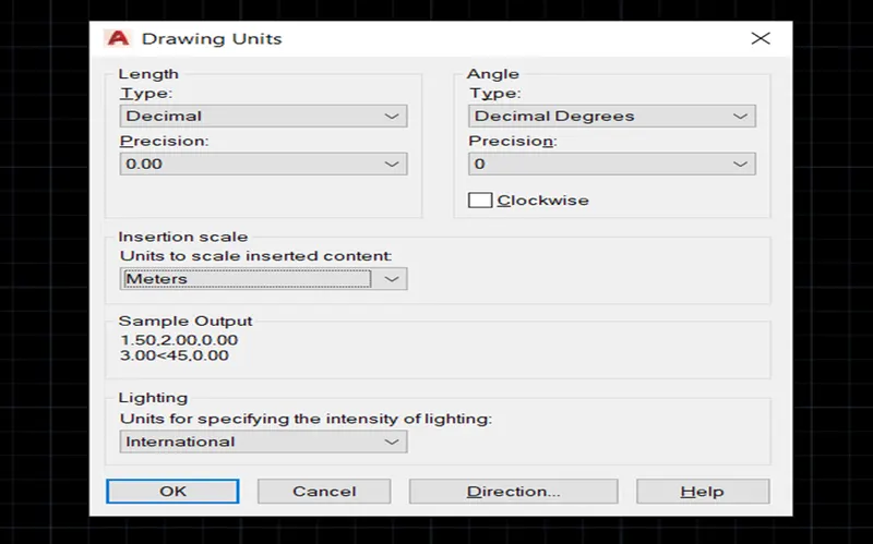
2. Go to 3d view and set UCS icon
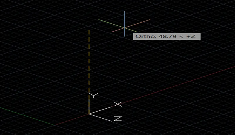
3.Go for rectangle option and create rectangle 0.9,0.25
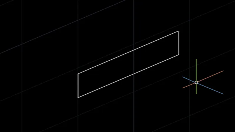
4.Again go for rectangle and draw rectangle0.5,0.4 and the use move command and pick the centre of rectangle and place the first rectangle centre

5.Again go for rectangle and create all rectangle (0.4,0.4 0.3,0.6 1.0,0.6 0.3,1.0) and the use move command and pick the centre of rectangle and place the previous rectangle centre
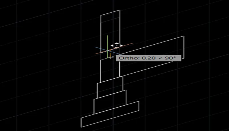
6.Move the upper rectangle 0.05 and join the use of line
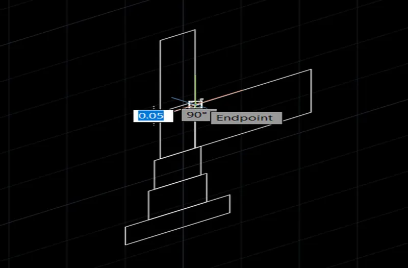
7.Go for rectangle and draw rectangle 1.15,0.15 and use of move command place the top corner of 3rd rectangle then create a line from line command end of the rectangle .3m as shown in figure then move corsair upper and create line .15 again create line .3m horizontal and .15 vertical again horizontal.3 and vertical .15m again horizontal .3m
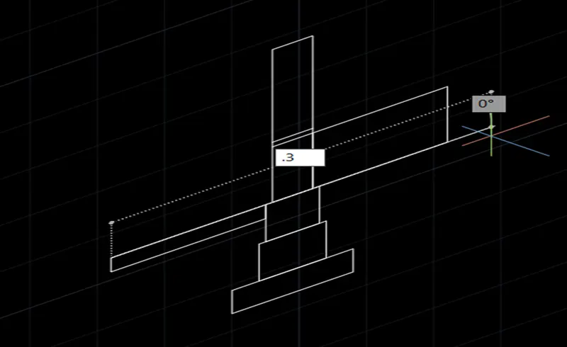
8.delete the first overlap line
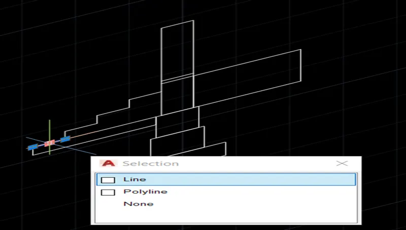
9.Trim the overlap line or polyline and join through the line

10.Show the dimension of all point
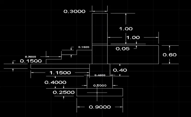
11.Type the name of drawing from text command
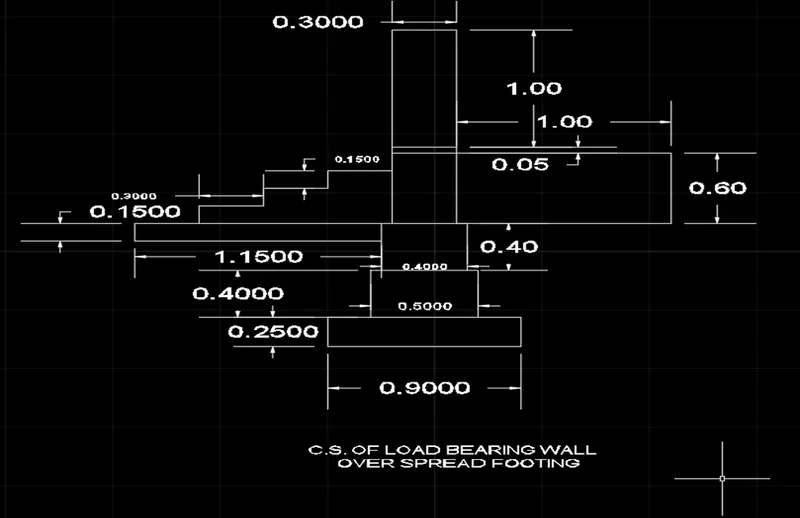
RESULT: To draw the susses fully diagram and mention the whole dimension.
C.S. ISOLATED FOOTING
AIM: To create a footing diagram in auto cad and learn about footing and detailing. And know about auto cad how to work.
PROCEDURE:
1.Open auto cad and set drawing units
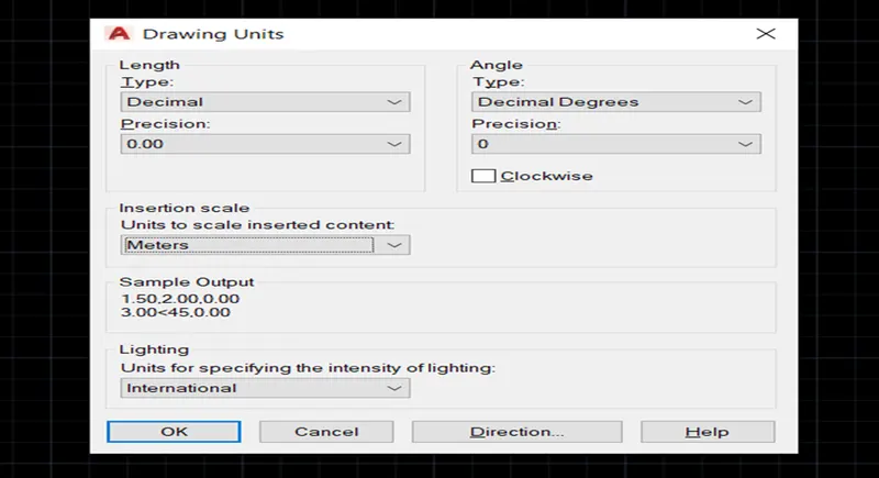
- Go to 3d view and set UCS icon
3.Go for rectangle option and create rectangle 1.0,0.15 and 0.24,1.6
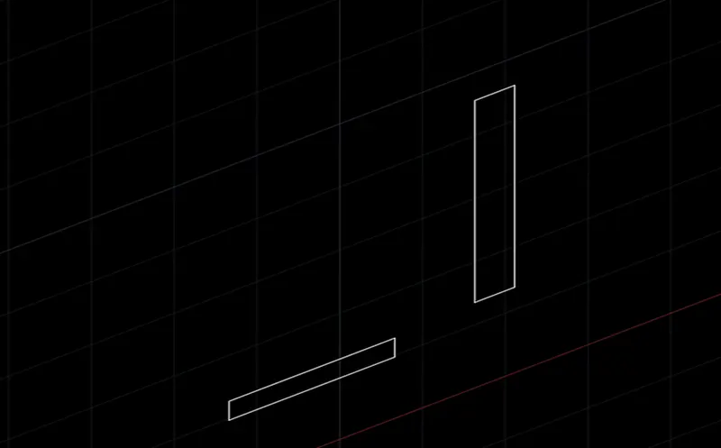
4. then go for move command and place mid-point of first rectangle
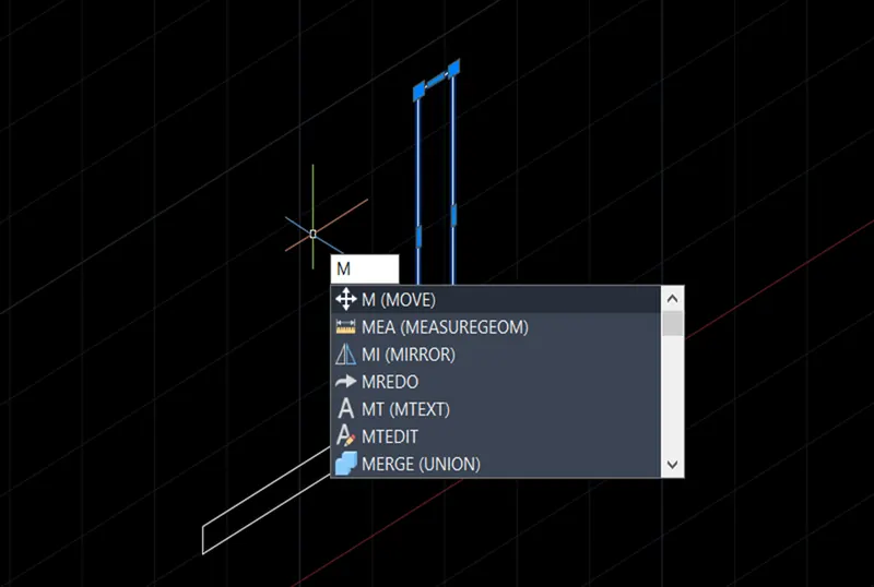
5.again move command use and move the upper side 0.25
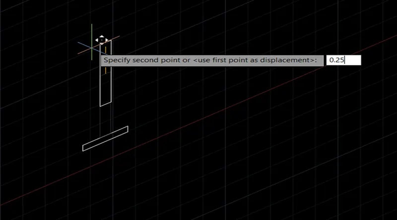
6.And join the corner of both rectangle for line command
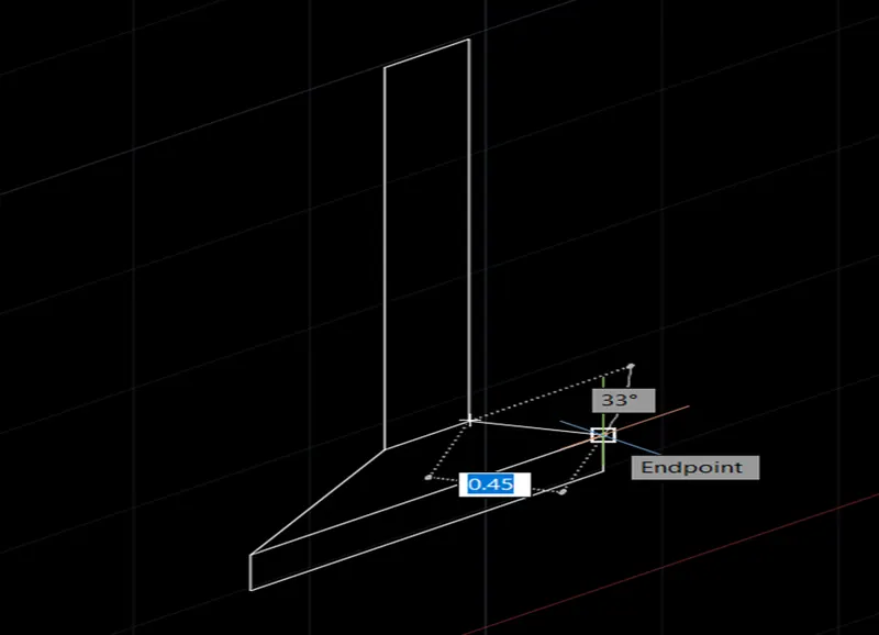
7.Then go for offset and use inner side of rectangle 0.04
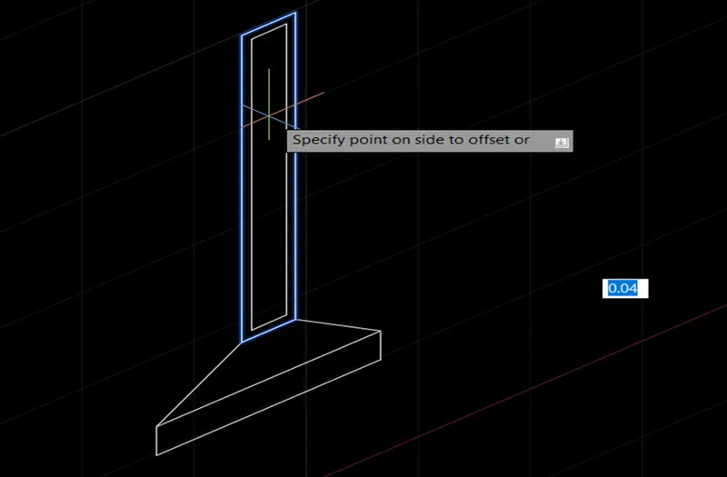
8.and trim the horizontal edge of rectangle
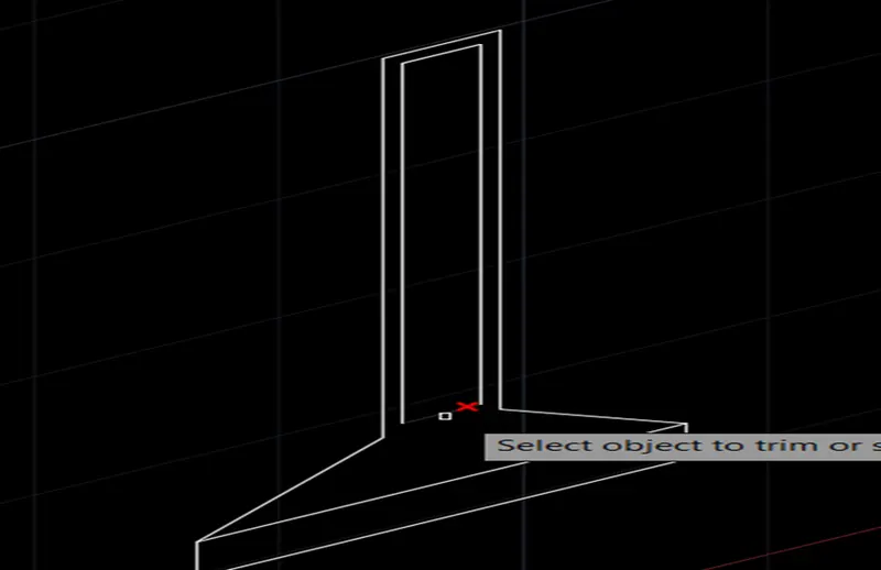
9.Go for offset and offset of lower portion 0.04
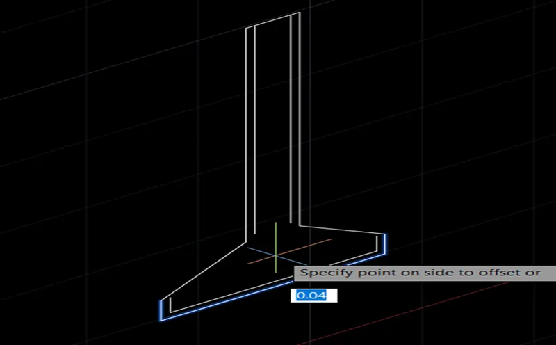
10.And join the line upper and lower portion through extend comman
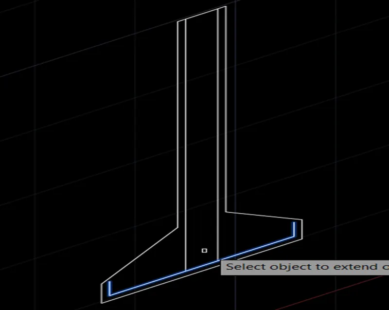
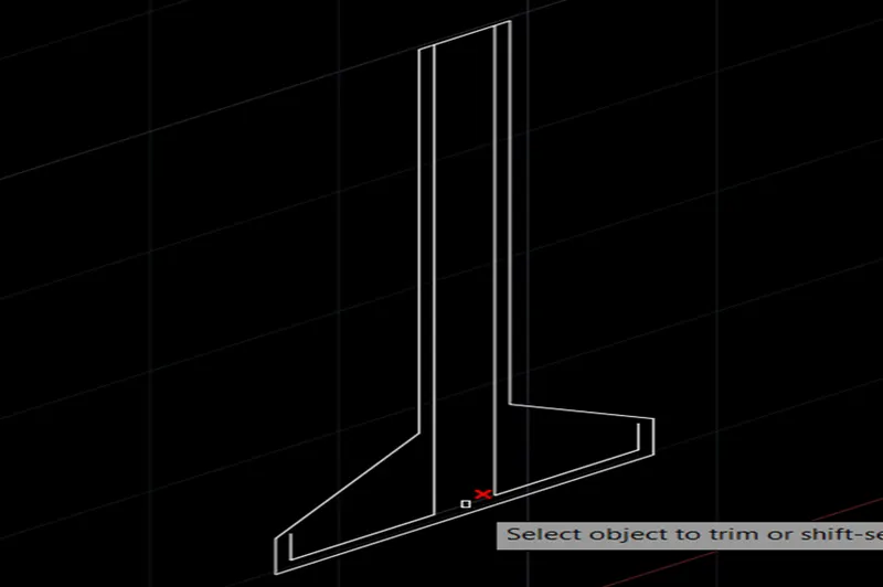
11.trim the mid of offset line
12.and go for offset 0.2m from upper line to lower line
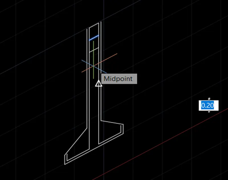
13.And trim the edge of lower offset line
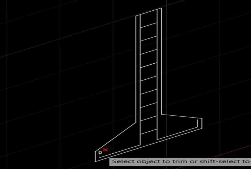
14.and draw the line 0.04 m for line command
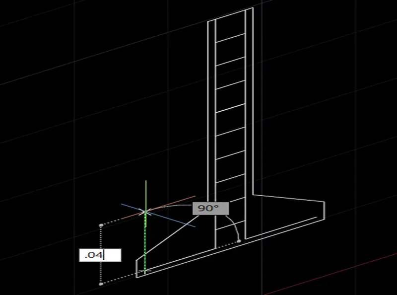
15.show the all dimension of the footing and get name the footing foe text command.
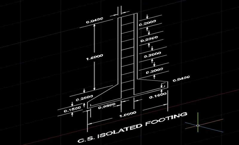
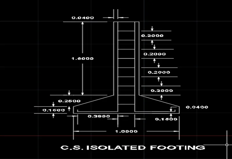
RESULT: To draw the susses fully diagram and mention the whole dimension.
LINE DIGRAM OF A TWO ROOM BUILDING
AIM: To create a building diagram in auto cad and learn about building and detailing. And know about in auto cad how to work.
PROCIDURE:
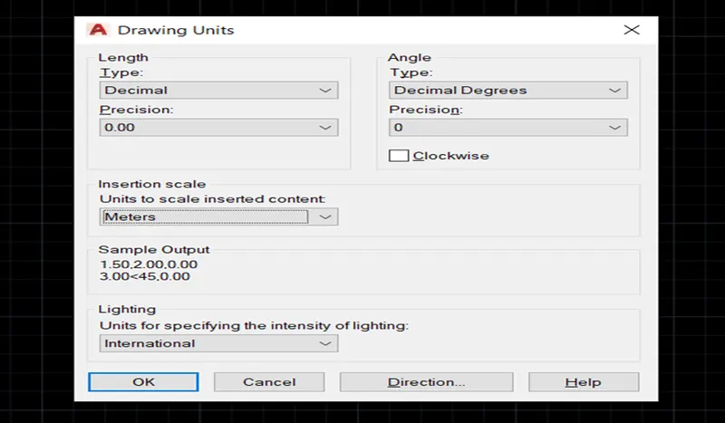
1 Open auto cad and set drawing units
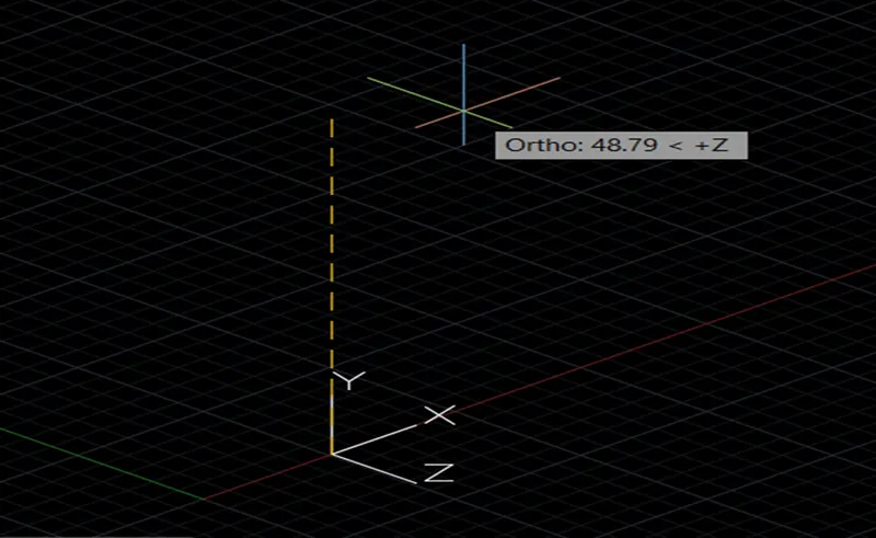
2.Go to 3d view and set UCS icon
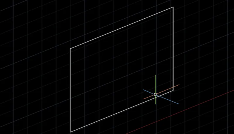
3.Go for rectangle option and create rectangle 3.6,3.6 M
4.And trim the inner edge as shown in figure
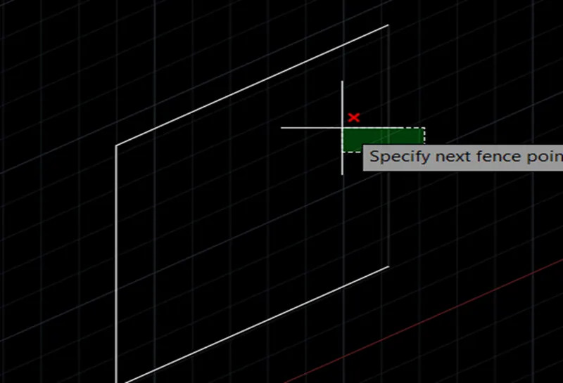
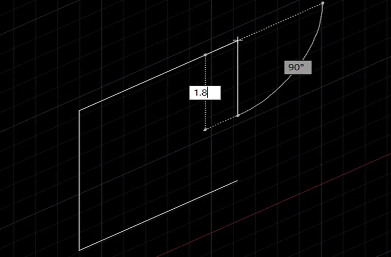
5.Create a line 1.8 m top of trim edge
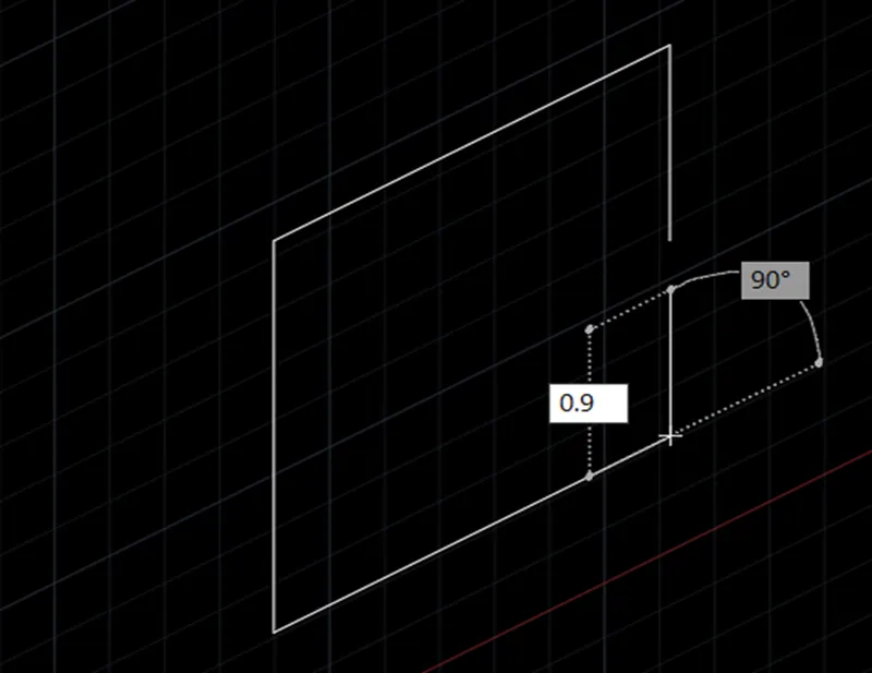
6.Again Create a line 0.9m bottom of trim edge
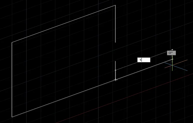
7.create a line 1m of both corner of rectangle
8.create a rectangle 4.2,3.6 m
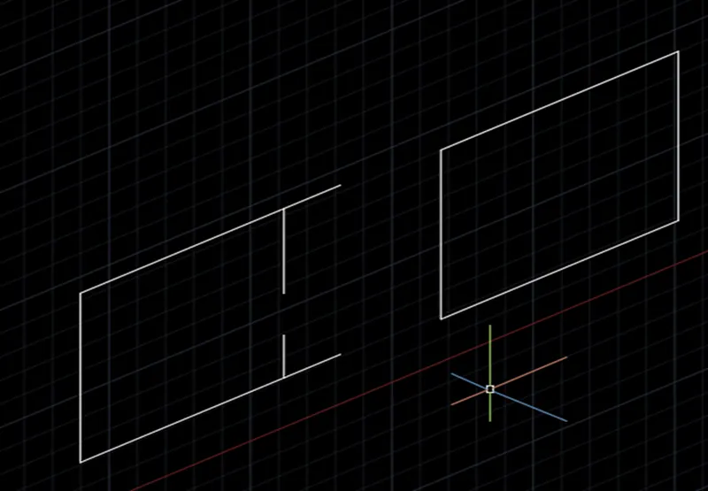
9.And move to rectangle for line edge
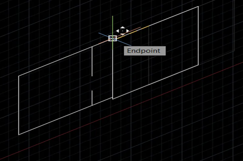
10.and trim the inner edge of the rectangle
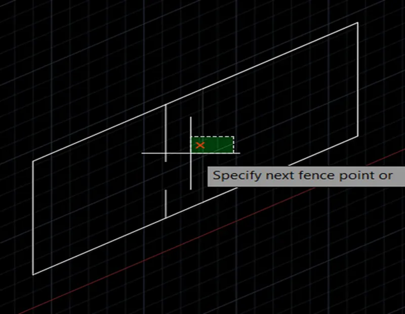
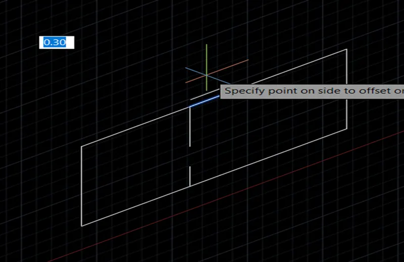
11.use the offset command and offset the both side line 0.3m three times
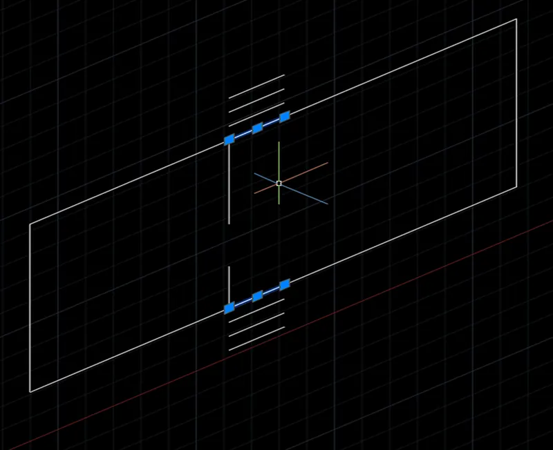
12.delete the first line of both side
13.Show the dimension of drawing and get name of the drawing
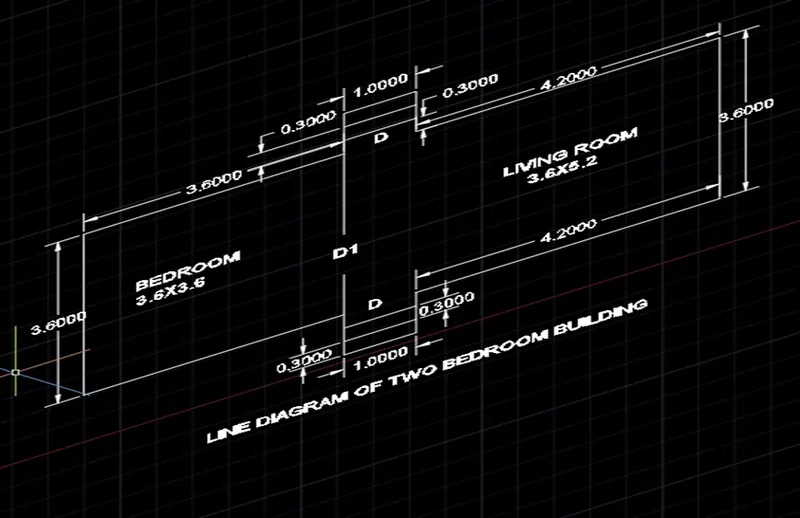
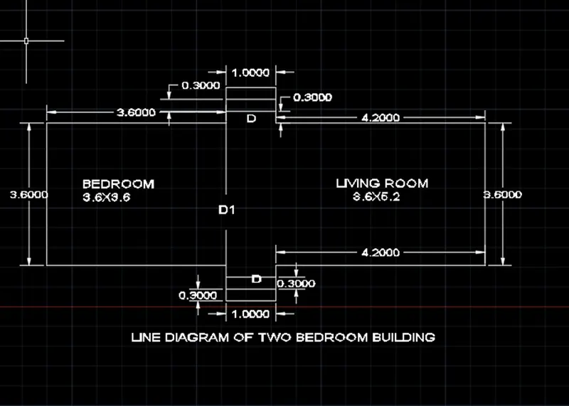
RESULT: To draw the susses fully diagram and mention the whole dimension.
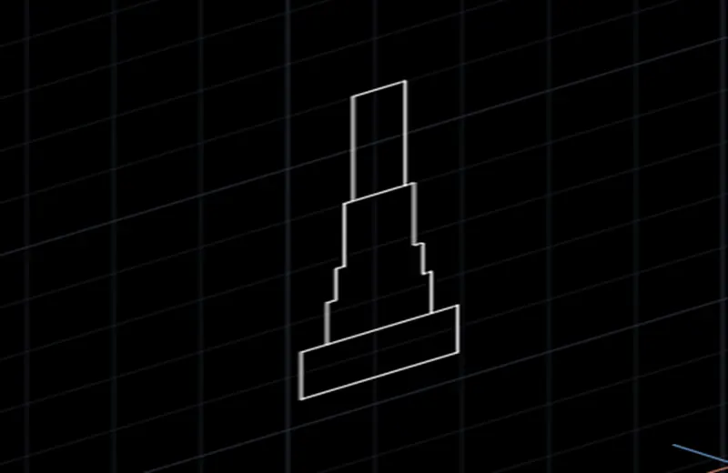
C.S. OF LOAD BEARING WALL SHOWING FOUNDATION DETAILS
AIM: To create a foundation diagram in auto cad and learn about foundation and detailing. And know about in auto cad how to work.
PROCIDURE:
1 Open auto cad and set drawing unit
2.Go to 3d view and set UCS icon
3.To create a rectangle 0.9,0.45 m 0.6,0.4m 0.5,0.3m 0.4,0.6m 0.3,1.0m

4.And move the centre of rectangle one by one
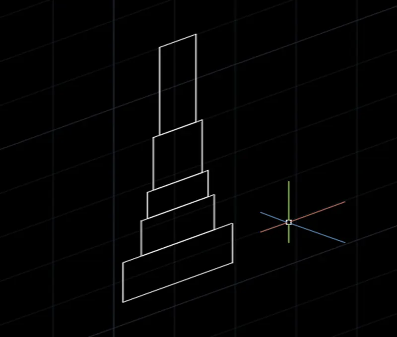
5.Then trim the over lap portion
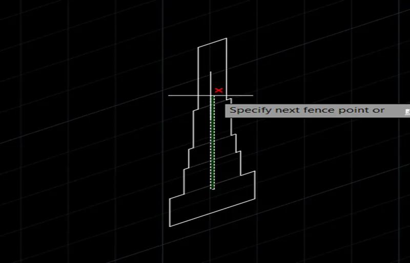
6.And join the lower and upper rectangle through line
7.give the dimension and name of the drawing
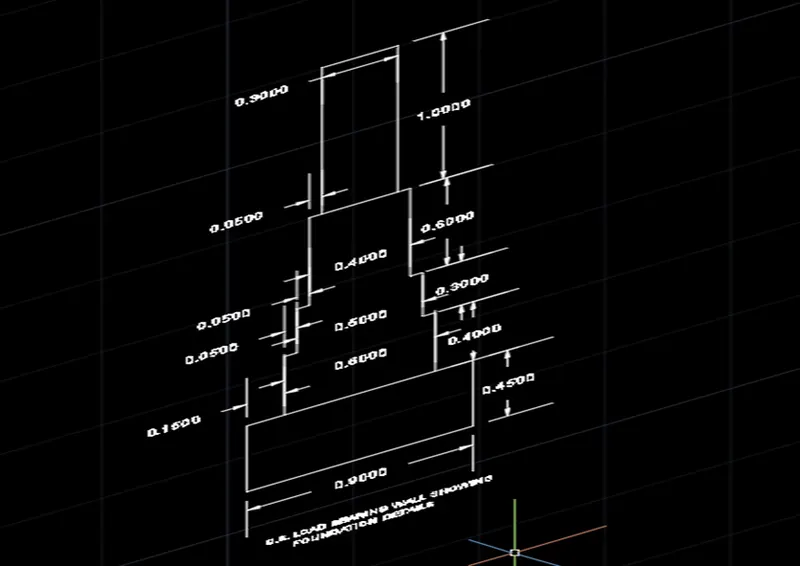
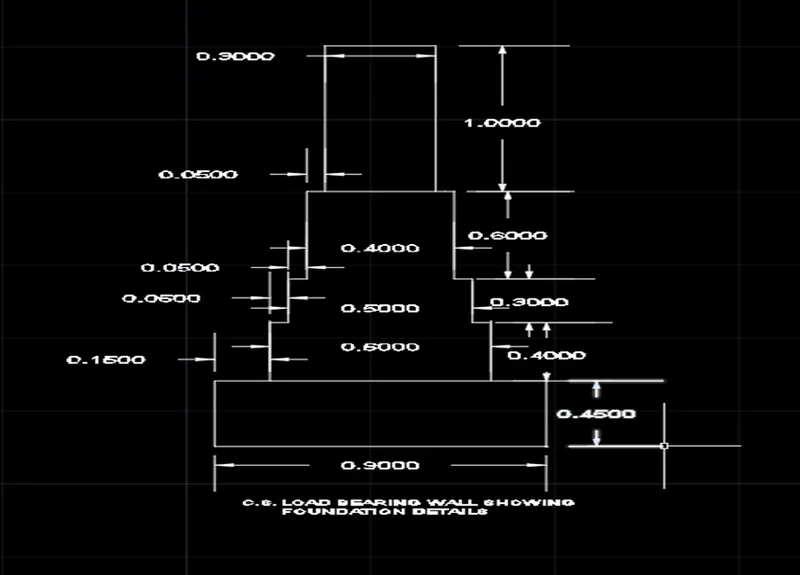
RESULT: To draw the susses fully diagram and mention the whole dimension.
STAIR CASE IN 3D PLAIN
AIM: To create a stair case diagram in auto cad and learn about stair and detailing. And know about in auto cad how to work.
PROCIDURE:
1 Open auto cad and set drawing units
2.Go to 3d view and set UCS icon
3.To create a rectangle 1.0,0.15 m
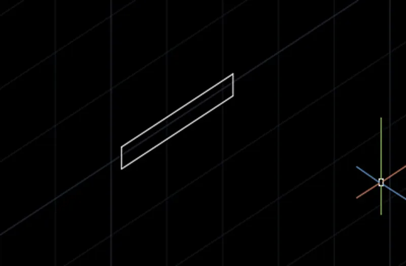
4.Set the UCS another plane
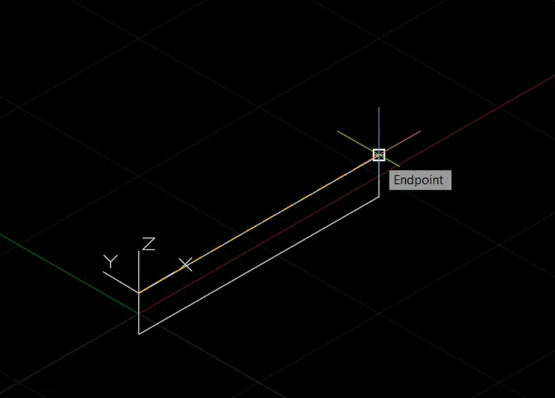
5.Then draw the line .3 m both upper corner of rectangle
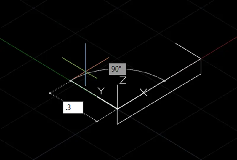
6.copy the rectangle and pest the end of line three times repeats this process and join the last line
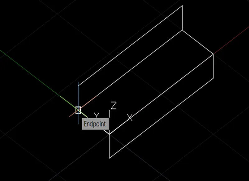
7.Again change the UCS and draw the horizontal .3m and vertical 0.15m line
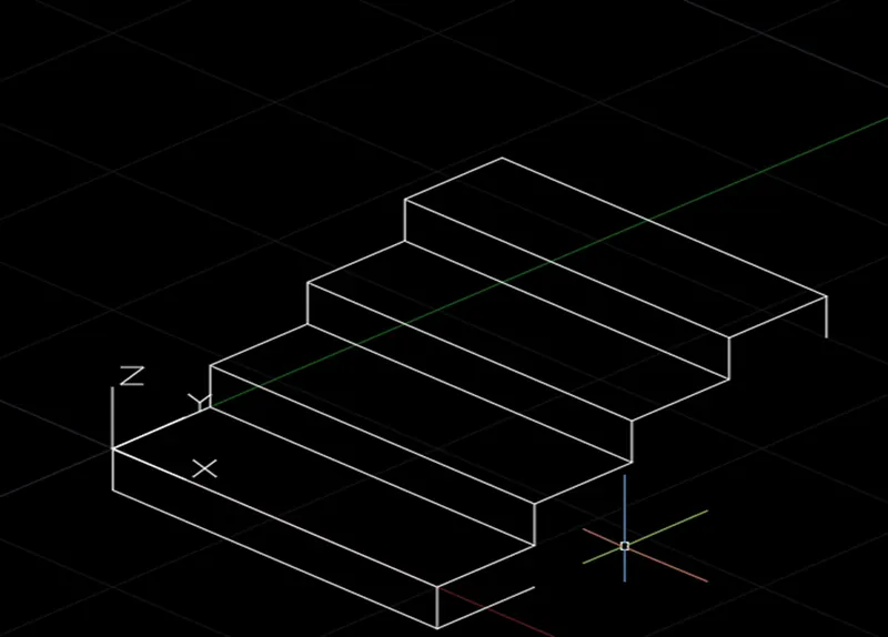
8.join the end point of the line
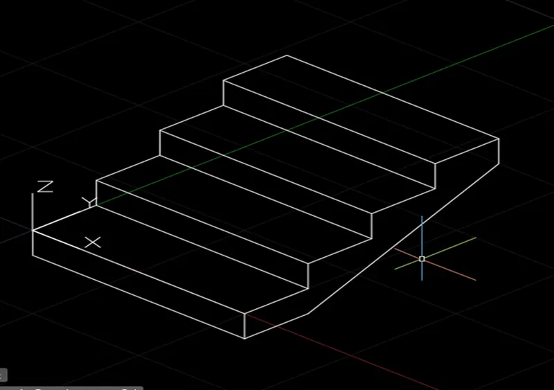
9.Detailing the drawing and give the name of drawing
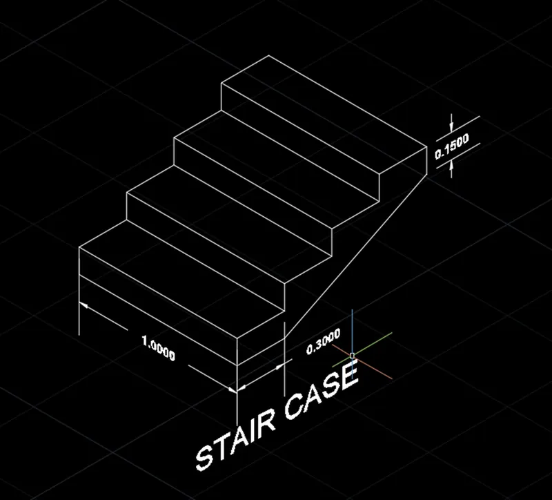
RESULT: To draw the susses fully diagram and mention the whole dimension.
ISOMETRIC VIEW OF THE GABLE WALL
AIM: To create a isometric gable wall diagram in auto cad and learn about wall and detailing. And know about in auto cad how to work.
PROCIDURE:
1 Open auto cad and set drawing units
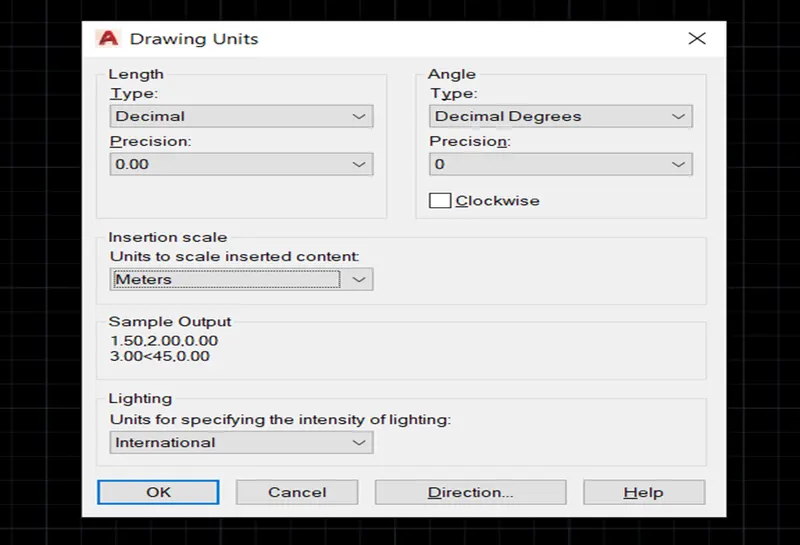
2.Go to 3d view and set UCS icon
3.Create a rectangle 3,3 and 1,2.42

4.move the rectangle centre of rectangle
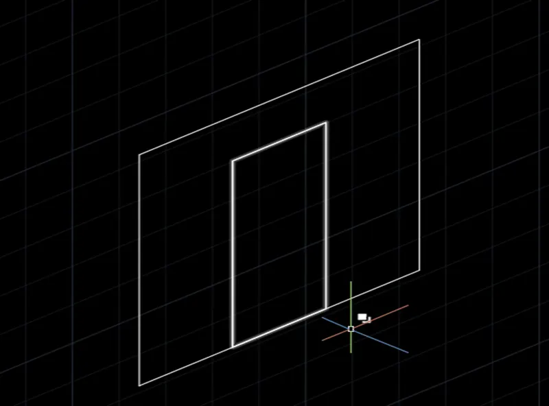
5.TRIM the over lap portion
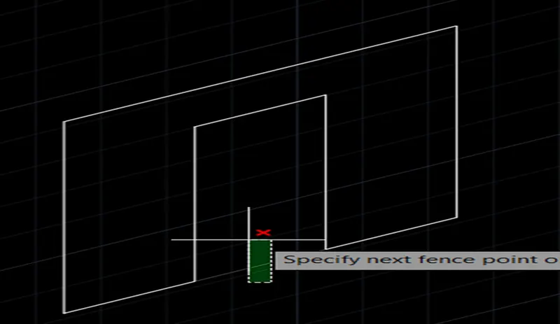
6.create a line mid-point of rectangle as shown figure
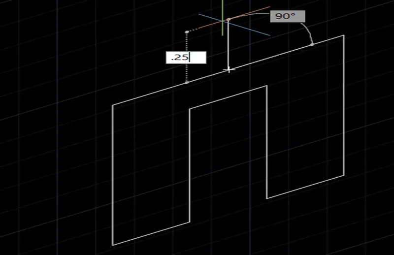
7.Trim the side portion of line
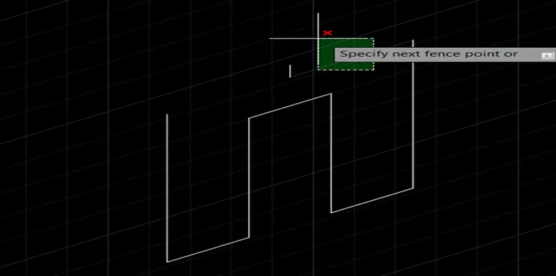
8.join the upper portion of line to rectangle corner
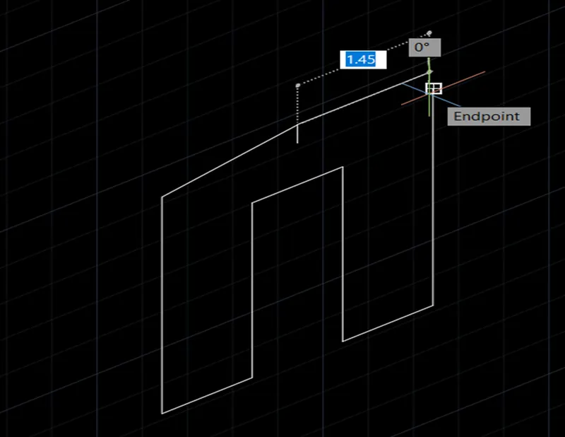
9.change the UCS and create a line .3m of each corner as shown figure
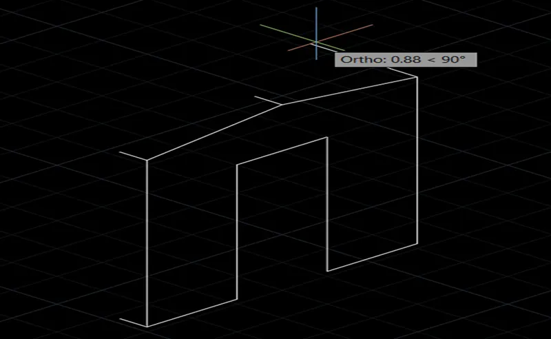
10.Join the line of every extend point
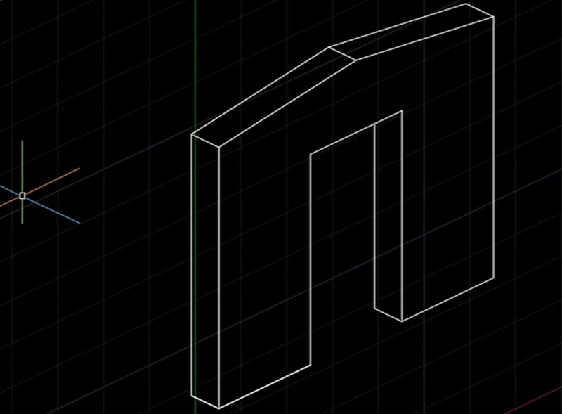
11.Show the detailing and give the name of drawing
RESULT: To draw the susses fully diagram and mention the whole dimension.