Reinforcement Detailing of Beams from ETABS output
Answer of the Question
AIM: Aim to the question is Detailed design of concrete buildings -1
OBJECTIVE:
- To understand or know the Design of Beam using ETABS analysis.
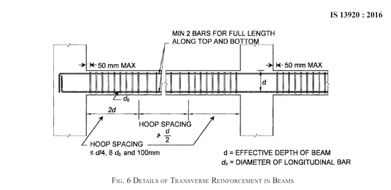
- To understand the basics of beam reinforcement detailing with respect to primary standards.
- To ensure the ductility reinforcement required by IS- 133920-2016 has been satisfied in ETABS design.
INTRODUCTION: there are certain rules we follows before,
- 1 Maximum reinforcement for shrinkage & temperature
- Reinforcement required for limiting crack-width
- Ultimate limit state design rebar requirement
- Ductility rebar requirement
What is sheare stress = `(Load)/( Area)`
Whichever is greater Should be drawn in RC beam detailing
- Minimum longitudinal reinforcement as per IS- 133920-2016 clause 6.2.1 As =360 `mm^2`
- Minimum shear (or) transverse reinforcement as per IS-456-2000 clause 26.5.1(1000mm spacing in the formula) Asv= 332`mm^2`
- Development length as per IS-456-2000 clause 26.2.1 Ld = 41x diameter of bar
PROCEDURE: TO COMPLETE THE ANSWER OF THE QUESTION WE HAVE TO FOLLOW THE FOLLOWING STEPS. (ETABS DESIGNING)
STEP-1
- Open the attached file
- Open the First floor
- and First we have to analyize the modal.
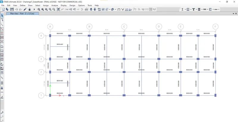
STEP-2
- After analyzing of the modal click to the 3d view
- We get the following modal.
- We get the maximum and minimum deflection in the status bar.
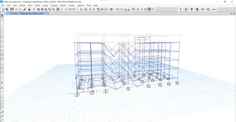
STEP-3
- Now Go to the concrete frame button.
- and analyze the concrete Design.
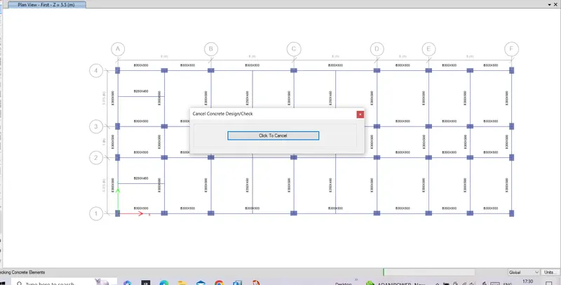
STEP-4
in the plan view various data is mention.
- Left support top requirement.
- Left support bottom requirement.
- mixed-pan top requirement.
- mixed-pan bottom requirement.
- Right support top requirement.
- Right support bottom requirement.
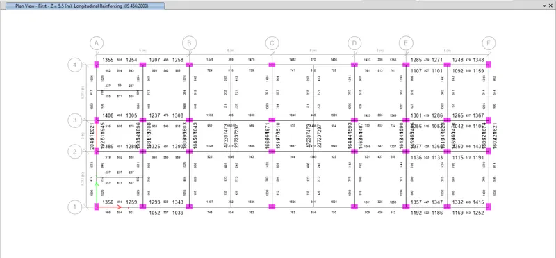
STEP-5
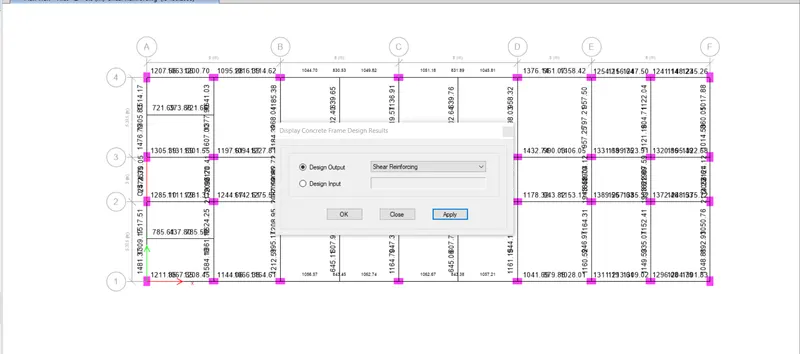
- Go to the concrete design and Drop-down the box click to the display design information
- change the option to shear reinforcement and click apply.
STEP-6
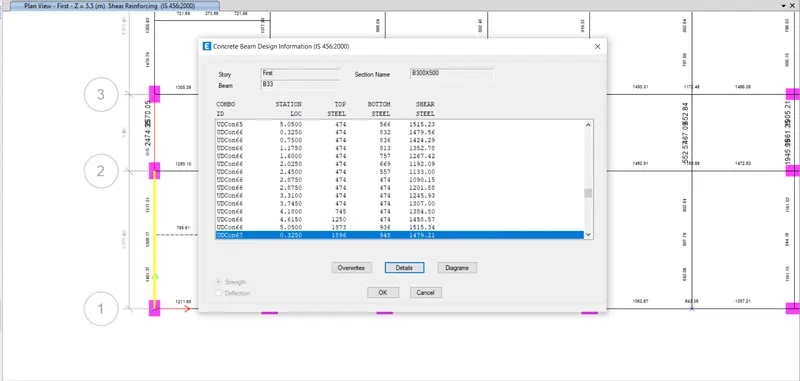
- Now we are check the details of particular section.
- To know the units of figure.
STEP-7
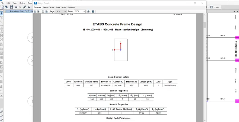
- Now click to the details.
- we get the shear reinforcement details.
STEP-8
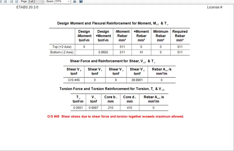
- Now in the plan one beam showing O/S
- it means the beam is a failure in the beam is Over-stressed.
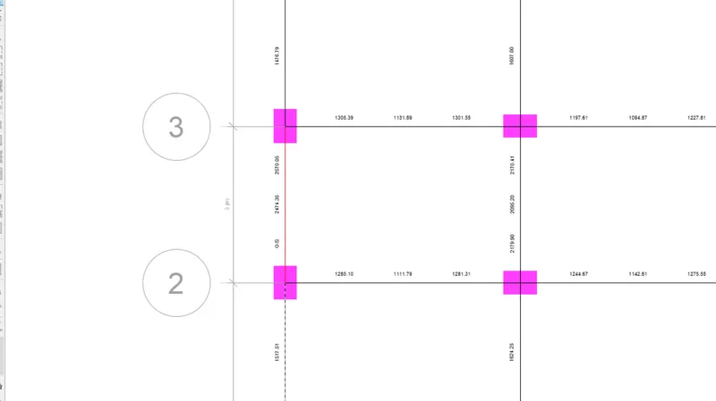
- in the beam report we can find the "The shear stress due to shere force torsion together exceeds maximum allowed."
STEP-9
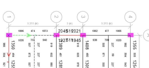
- Longitudinal Reinforcement of Beam at Grid-3 from ETABS (mm2):
.
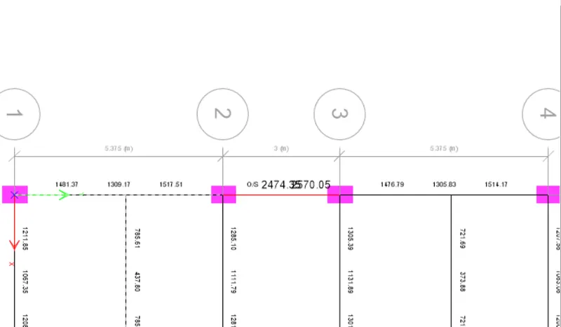
- Shear reinforcement of Beam At Grid-3 from ETABS(cm2/1000mm):
- Longitudinal Reinforcement of Beam at Grid-3 from ETABS (mm2):

- Shear reinforcement of Beam At Grid-3 from ETABS(cm2/1000mm):

STEP-10
STEP-11
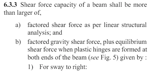
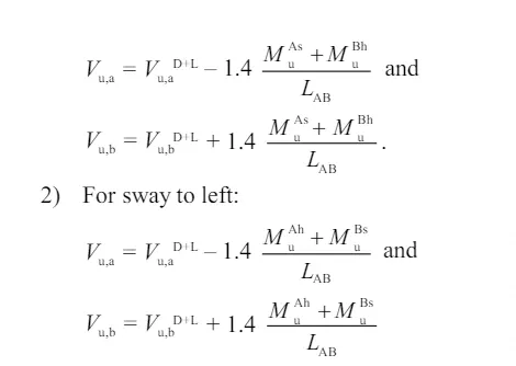
1.4 times of Support A sagging moment + Support B hugging moment
For Sway shear force to Right,
- Mas= 174kNm
- Mbh= 293kNm
- Lab= 4.725m
- Vd+1 = 92 kN
Vu,a = 46kN , Vu,b= 230 kN
For Sway shear force to Left.
- Mah =234 kNm
- Mbs=155kNm
- Lab = 4.725m
- Vd+1= kN
Vu,a = 185 kN, Vu,b = 45kN
STEP-12
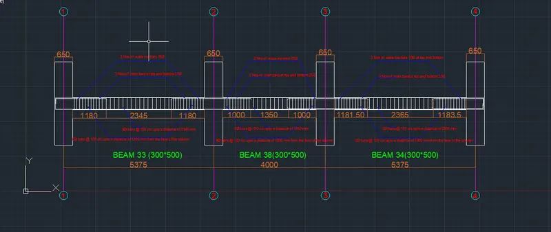
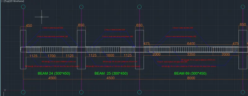
Detailing of beams using AutoCAD
Grid A
Grid 3
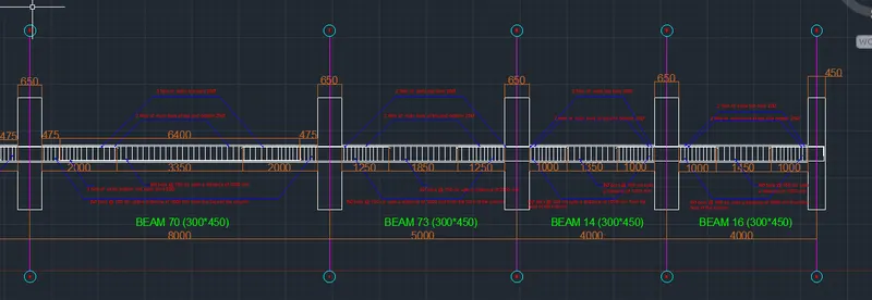
RESULTS: The following has been illustrated properly along with results:-
- Analysis and design the RC moment frame for G+4 building
- Providing details of longitudinal and shear reinforcement for beam along with elevation details
- Providing reasons for failure of the middle span along grid A
- Calculating value of maximum shear forces in any of the span