Reinforcement Detailing of Beams from ETABS output
Challenge 7 – Detailed design of concrete buildings -1
Detail design of beams in Etabs 2018.
The ETABS file for a G+4 building is provided. Run the analysis and design the RCC Moment ResistingFrame. The following challenge deals specifically with two continuous beams in the 1st floor.
1) 3 span continuous beam along grid A
2) 7 span continuous beam along grid 3
Address the following issues thereafter.
• Provide details of longitudinal and shear reinforcement for the two continuous beams. Sketch the beam elevation details or draft it using autocad software. A sample of how beam elevation details is prepared in consultancy firms is provided below. Participants can prepare it as per their preference:
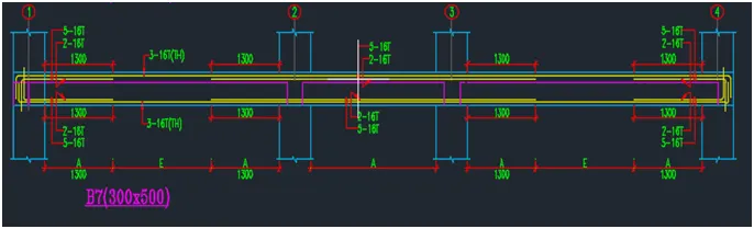
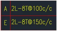
• Provide reasons for failure of the middle span along grid A. What are the possible ways this issue can be resolved?
• Calculate value of the maximum shear force in any one of the spans in both the continuous beams, as per clause 6.3.3 (b) in IS 13920 – 2016. Also, confirm these values from shear force demand calculated by ETABS.Please note that if longitudinal reinforcement provided is more than required (as per ETABS results), the shear force demand will vary from what is provided by ETABS.
Aim: To desing and detail the continous beams along grid A and 3 from the given G+4 building using E-tabs and calculation.And also provide reasonsn for failure of a beam along grid A and calculate the maximum shear force in any one of the spans as per clause 6.3.3 of IS 13920-2016.
Introduction: E-tabs is a anlaysis software which ultimately provides us the area of steel required for a element in the model with respect to the analysis of the structure given. The shear reinforcement of the E-tabs is not considered instead it is designed as per the standards of the codes and capacity of the the shear.During earthquake the structure is subjected to sway along translational directions and it is to be checked.
Steps:
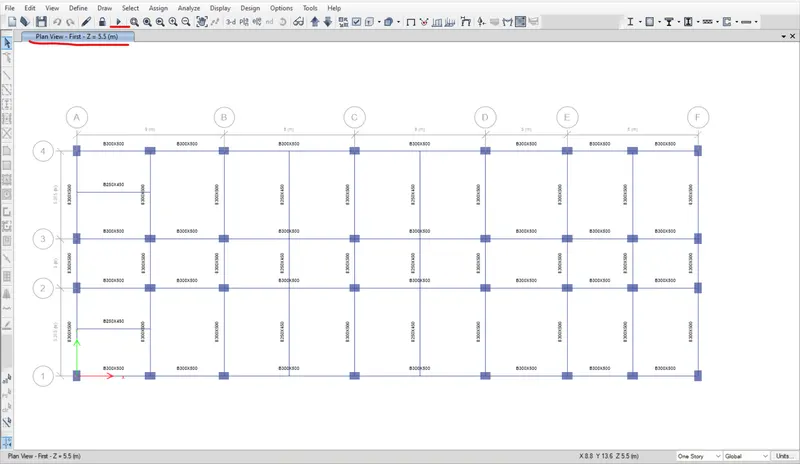
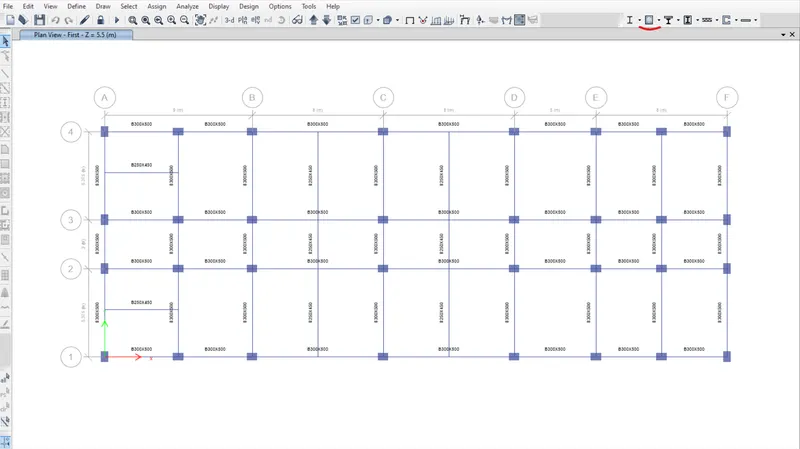
- Initially the attachment is downloaded and analysis is done using the run analysis option in the Analyze tab of the E-tabs software
- After analysis, design is done using concrete frame deisign tool in the right top of ribbon
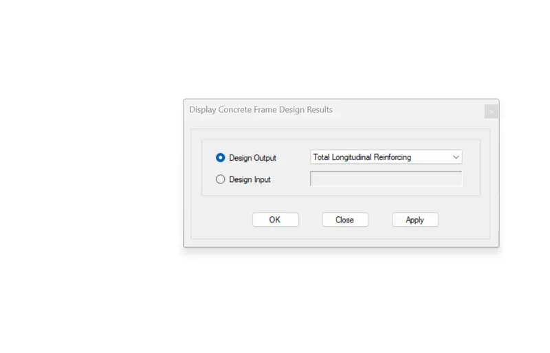
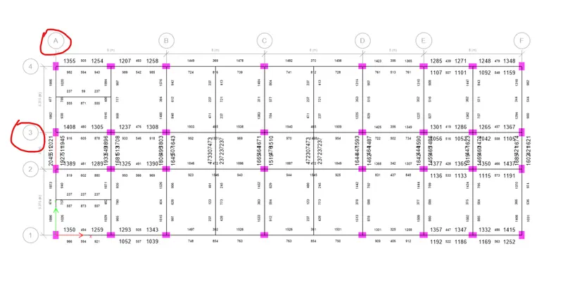
- Then using the display design info and total longitudinal reinforcing options in the same concrete frame design tab, the values of the steel required are displayed in the frames of the structure.
Design along Grid 3:

- The top longitudinal reinforcement varies from 1237mm2 to 1940mm2 at the ends whereas, bottom value varies from 728 to 1501mm2
- Generally in beams extra rods are provided at top ends and bottom middle where the hogging moments will be more at the top ends and sagging moments will be high at the bottom middle
- Hence a certain amount of bar will run throughout the beam at top and bottom and the extra rods are provided at the ends of top and middle of bottom
- The extra rods provided are upto a defined distance which is of L/3 at top and L/6 at bottom
- As per the requirements 2nos of 25mm rod is provided throghout the beam at top and extra 2nos of 25mm or 20mm rod is provided.
- The rods provided sums to a area of 2-T25+2-T25(E)=1962.5 mm2 which satifies the required highest 1940mm2.
- At bottom 2nos of 20mm rod is provided thoroughout the beam and 2nos of 25mm or 16mm is provided as per the requirements
- The rods provided sums to a area of 2-T20+2-T25(E)=1609mm2 which satifies the required highest 1501mm2.

- The shear provided is 10#2L @100mm C-C @ends and 10#2L @150mm C-C @ middle
- It is provided in such difference because of the code standards and as per shear requirement. The code suggests to provide not more or less than 100mm spacing of shear links for a distane of d/2 in which d is the effective depth of the beam.
Grid A:
- For grid A the highest value at the top is 2045mm2 and at the bottom is 1945mm2
- At top as per the requirements 2nos of 25mm rod is provided througout the beam and 2 nos of 32mm extra rods are provided at the supports
- The rods provided sums to a area of 2-T25+2-T32(E)=2500 mm2 which satifies the required highest 2045mm2.
- At bottom as per the requirements 2nos of 25mm rod is provided througout the beam and 2 nos of 25mm extra rods are provided at the supports.
- The rods provided sums to a area of 2-T25+2-T25(E)=1962 mm2 which satifies the required highest 1945mm2.
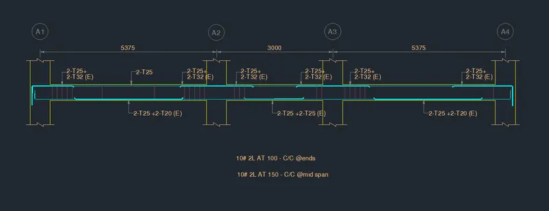
- Shear reinforcing is provided as same as Grid 3 beam design.
• Provide reasons for failure of the middle span along grid A. What are the possible ways this issue can be resolved?
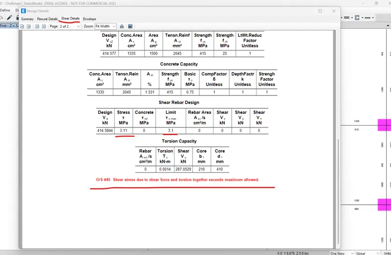
The reason of failure from the above image can be interpreted as required shear exceeds the shear limit as per IS 456 standards i.e, over shear. Shear force is defined as load per area hence, load can be decreased, or the grade of concrete can be increased for a particular beam for reducing the shear.
• Calculate value of the maximum shear force in any one of the spans in both the continuous beams, as per clause 6.3.3 (b) in IS 13920 – 2016. Also, confirm these values from shear force demand calculated by ETABS.Please note that if longitudinal reinforcement provided is more than required (as per ETABS results), the shear force demand will vary from what is provided by ETABS.
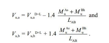
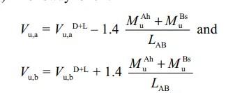
During earthquake the building is subjected to sway towards left and right and shear force is calculated as per the code standards of IS13920-2016. The formula is
for sway right
for sway left
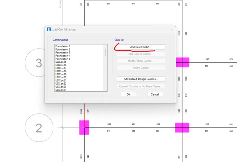
Vu D+L represents the shear force only under dead and live load conditions, which is calculated by creating a load combination of the same using define tab and add a copy of the combo option and the factors are taken as 1.2 for all loads.
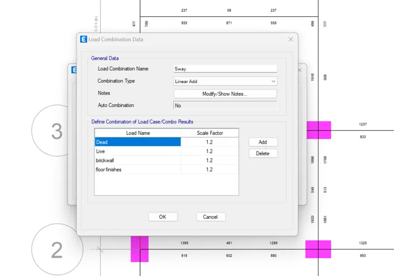
From the combinations the values are found to be
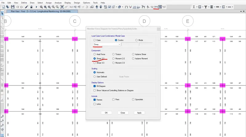
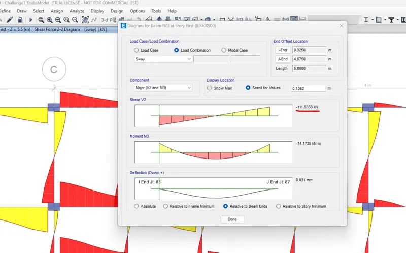
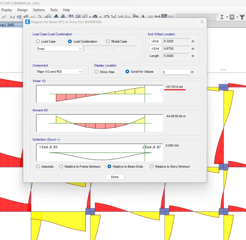
and the hogging and sagging moments at the ends are calculated from shear details tab of the design details of a particular beam to be calculated.
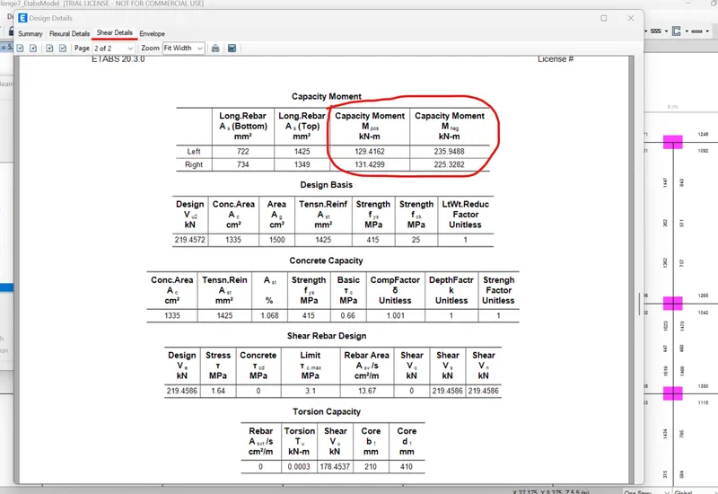
from the values the shear values are calculated as
To right
Vu,a=12.5KN-m
Vu,b=178.49Kn-m
To left
Vu,a=8.96Kn-m
Vu,b=210.41Kn-m
The shear force provided is calculated using the IS456 formula
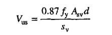
fy=415N/mm2
Asv=157mm2
d=450mm
Sv=100
Upon calculating Vus=255Kn-m which is higher than the highest shear value 210.Kn-m hence the given reinforcement is sufficient.