Reinforcement Detailing of Beams from ETABS output
AIM: The main aim of this challenge is to prepare the reinforcement detailing of beams from E-tabs output.
INTRODUCTION:
in this, the model G+4 given in the question have analysed using E-tabs software and the following questions are solved for given spans i.e
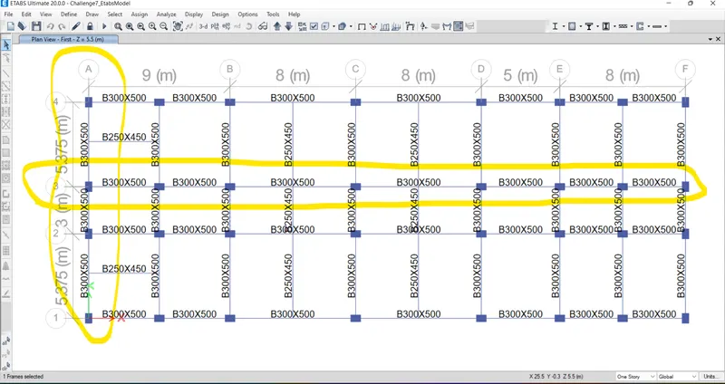
1) 3 span continuous beam along grid A
2) 7 span continuous beam along grid 3
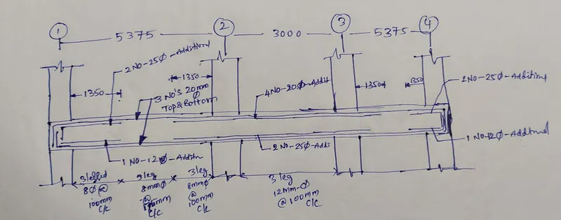
- Provide details of longitudinal and shear reinforcement for the two continuous beams. Sketch the beam elevation details or draft it using autocad software
-
Provide reasons for failure of the middle span along grid A. What are the possible ways this issue can be resolved?
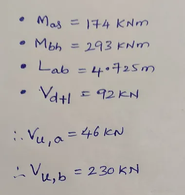
- Calculate value of the maximum shear force in any one of the spans in both the continuous beams, as per clause 6.3.3 (b) in IS 13920 – 2016. Also, confirm these values from shear force demand calculated by ETABS.Please note that if longitudinal reinforcement provided is more than required (as per ETABS results), the shear force demand will vary from what is provided by ETABS.
PROCEDURE:
- starting with the E-tabs software
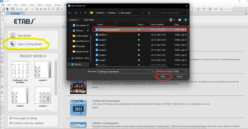
- opening the file i.e challenge 7 given in the question
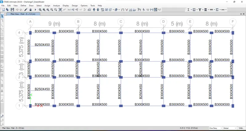
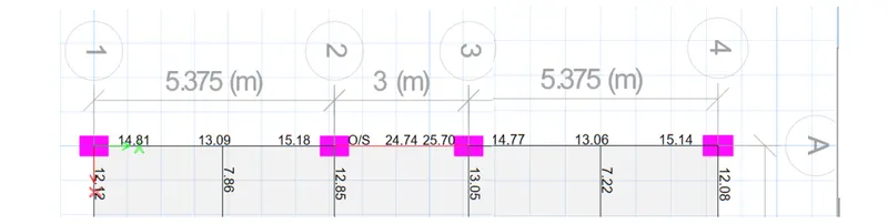
- the spans which are asked in the question are shown below
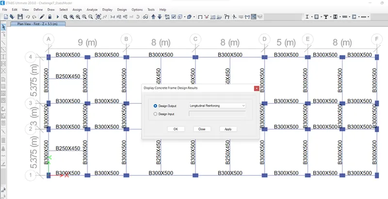
- after that, the model is analysed for results,then the model is also analysed for longitudinal reinforcement details which is shown below
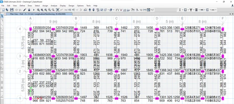
- taking the screen shots of longitudinal reinforcements of asked spans i.e
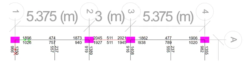
1) 3 span continuous beam along grid A
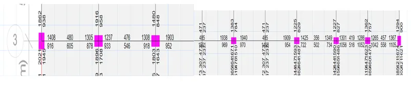
2) 7 span continuous beam along grid 3
1.
2.
- also taking the screen shots of shear reinforcement details which are in centimeter square (cm^2)
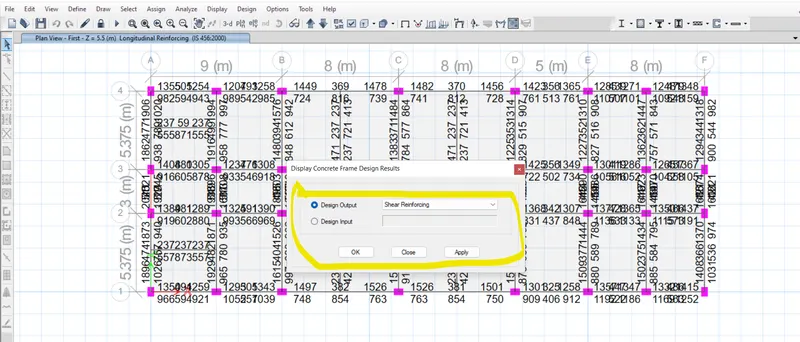

- the reinforcement model is shown below for both longitudinal and shear for both spans given in question and the rules for making the reinforcement details
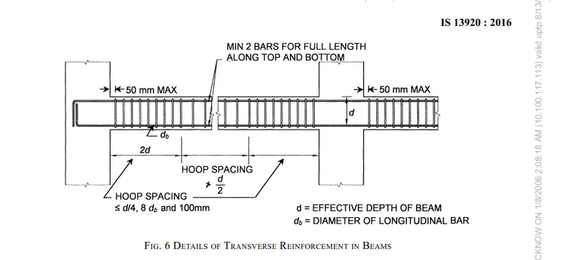
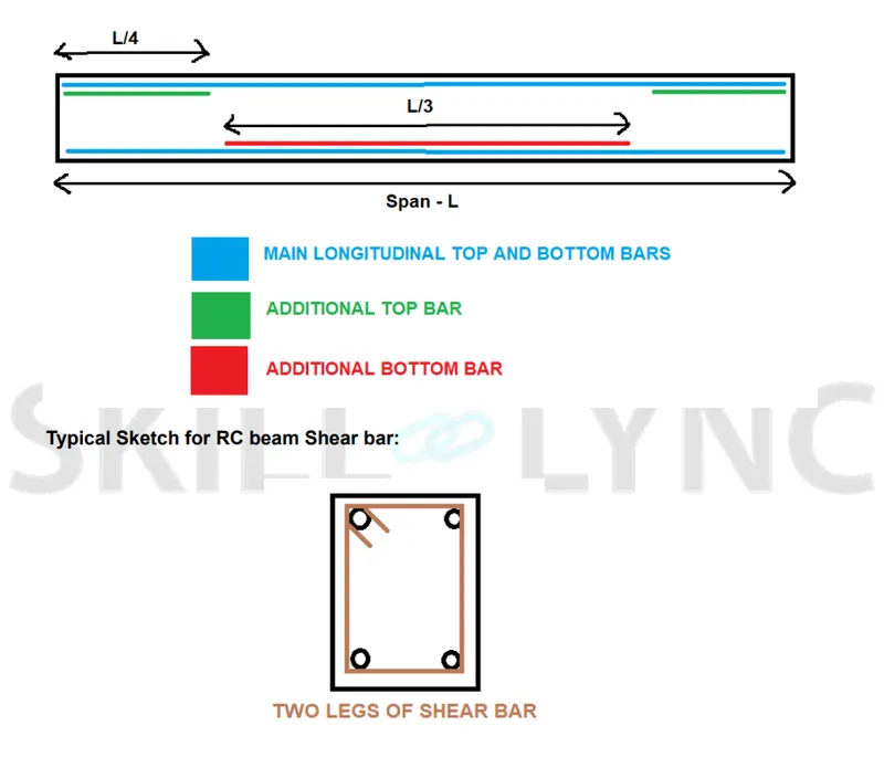
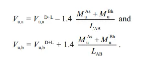
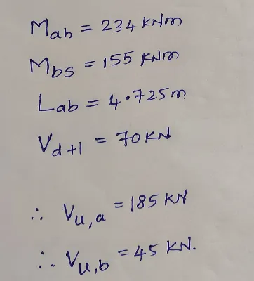
- now, the calculation of sway shear by using the below formulas from clause 6.3.3 of IS 13920:2016
for sway to right :
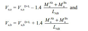
for sway to left :
RESULT:
the results are shown below for the above question
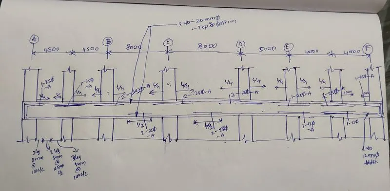
a) The sketches of the reinforcement details of beam are shown below
b) hence, the beam along grid A having three spans. The middle span having the length 3meter is failed in shear check due to over stresses is shown below
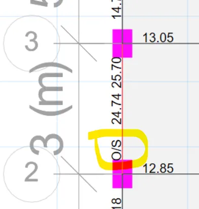
it is passed by providing the extra grade of concrete or decreasing or increasing load applications
c) in this, they asked to calculate sway shear to left and right and mention the required shear need to provide. we have calculated in procedure i.e Vu,a= 185KN and Vu,b=230KN. hence shear should not less than calculated values .