Reinforcement Detailing of Beams from ETABS output
AIM-Detail design of beams in Etabs 2018.
Minimum longitudinal Reinforcement as per IS 13920:2016 6.2.1
Criterias
- Minimum Reinforcement for shrinkage and temprature
- Reinforcement required for limiting crack width
- ultimate limit state design rebar requirement
- Ductility Rebar Requirement
and Analysis the model
Display Design Info> go for the longitudinal reinforcement 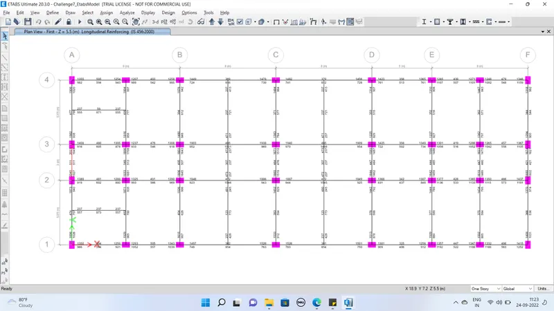
Reinforcement diagram of Grid A:
Max Ast at bottom support = 1925 mm2
Max Ast at bottom middle = 789 mm2
Max Ast at top support = 2045mm2
Max Ast at top middle = 511mm2
- So providing 3 bars of 20mm (942) and 5bars of 16mm (1004) at bottom
Calculation =3.14*.25*3*400+3.14*.25*5*256 = 1946>1925 (Hence safe)
- Provide 4 bars of 20mm (1256) and 4 bars of 16mm (804) at top
Calculation =3.14*.25*4*400+3.14*.25*4*256 =2059 >2045mm2 (Hence safe)
Now Check the beam in shear
by Etabs Design Checking the shear stresses in beam
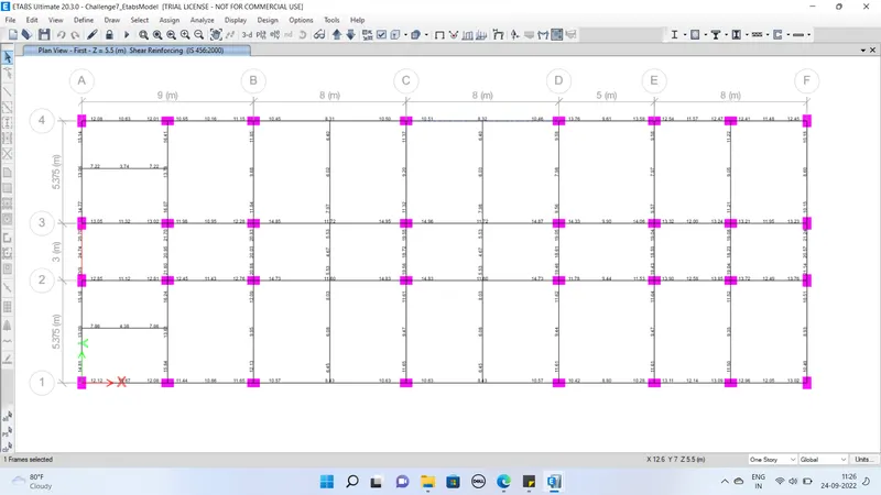
6.3.2 The minimum diameter of a link shall be 8 mm. (IS 13920:2016)
Maximum shear Reinforcement Required in the Beam is 25.70 Cm/m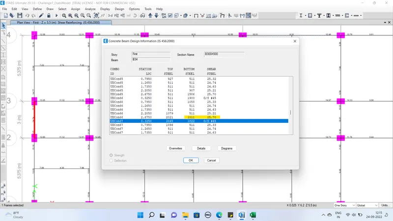
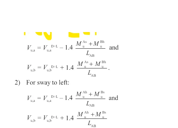
Formula For shear sway calculation
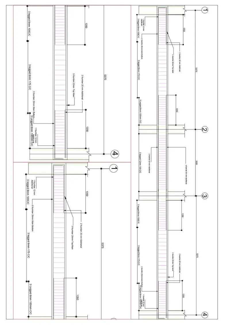
Longitudinal Reinforcement and Shear Reinforcement Drawing Beam of grid -A
Span 1-2
- Providing 3 legged 8 mm Diameter bars with spacing of 100mm at distance 2D
- At middle section 3 legged 8mm bars with 175mm C/C spacing provided
Span 2-3
- Providing 3 legged 12 mm Diameter bars with spacing of 100mm at distance 2D
Span 3-4
- Providing 3 legged 8 mm Diameter bars with spacing of 100mm at distance 2D
- At middle section 3 legged 8mm bars with 175mm C/C spacing provided
Calculation =(11*3.14*0.25*3*100)/100
=25.905 >25.70
FROM Etabs Analysis Reinforcement diagram of Grid 3:
Max Ast at bottom support = 1042 mm2
Max Ast at bottom middle = 1501mm2
Max Ast at top support = 1940 mm2
Max Ast at top middle = 485mm2
So providing 2 bars of 12mm (226) and 4 bars of 16mm (804) at bottom
Calculation =3.14*.25*2*144+3.14*.25*4*256 = 1029~1042
Provide 3 bars of 20mm (942) and 5 bars of 16mm (1004) at top
Calculation =3.14*.25*3*400+3.14*.25*5*256 = 1029~1042
Longitudinal Reinforcement details for GRID -3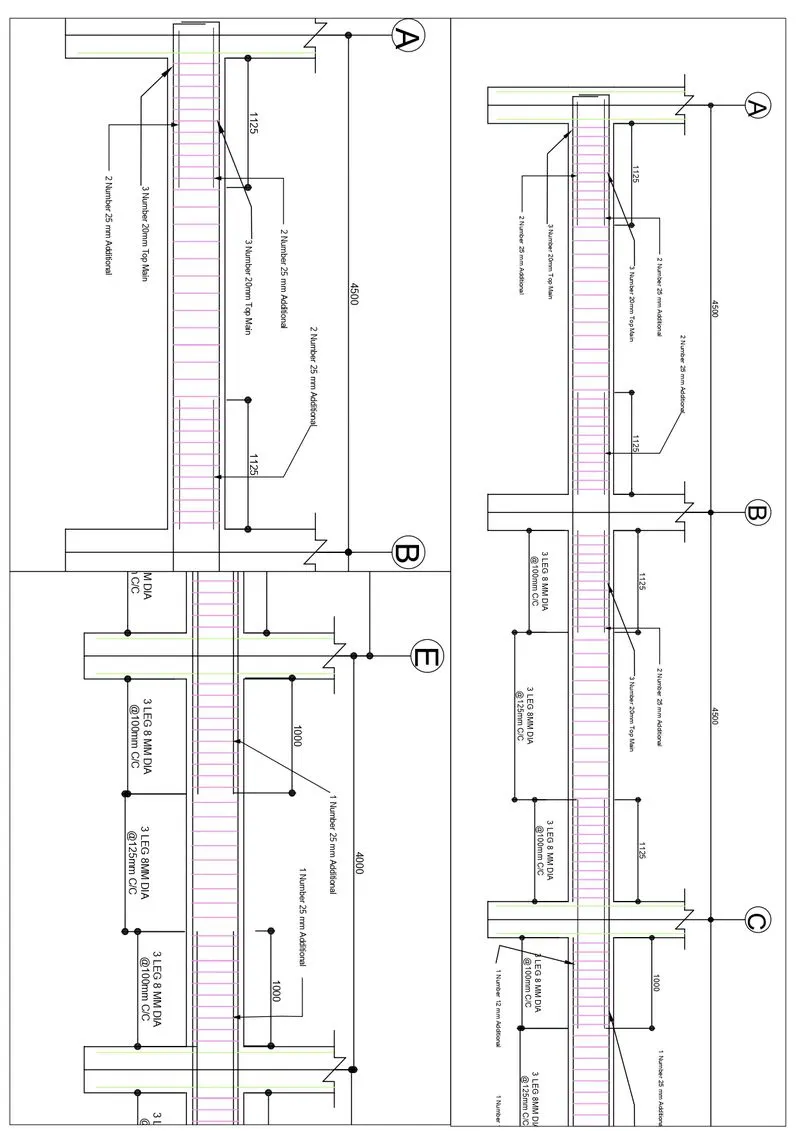
Provide reasons for failure of the middle span along grid A. What are the possible ways this issue can be resolved?
- In the overstressed beam there is negligile amount of torsion but there is huge amount of shear force there so we have only three option to make the beam understress
- so as we know that the Area of cross section of the column is directly propotional to the strength of the beam so we should increase the area of the cross section
- and if can reduce the imposed forces there than we can make the beam understressed
- other one option is to increase the grade of concrete to provide the strenth to the column