Reinforcement Detailing of Beams from ETABS output
- QUESTION :
- Calculate value of the maximum shear force in any one of the spans in both the continuous beams, as per clause 6.3.3 (b) in IS 13920 – 2016. Also, confirm these values from shear force demand calculated by ETABS.Please note that if longitudinal reinforcement provided is more than required (as per ETABS results), the shear force demand will vary from what is provided by ETABS.
- AIM : DETAILS DESIGN OF BEAM IN ETABS 2017
- PROCEDURE :
- STEP 1
- OPEN THE FILE
- First one the file which is attached to our question .
- so that click on attachment and download the file
- then open the ETABS 2017 SOFTWARE
- then click on FILE option
- then click on IMPORT OPTION
- select the file type as b2k and then click ok .
- file is open now
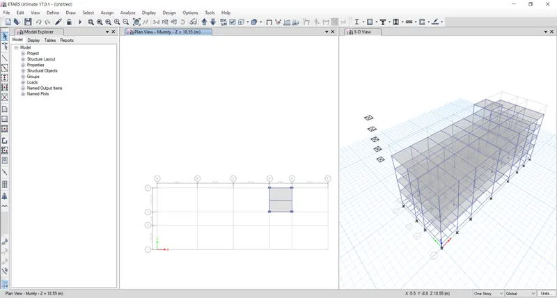
- STEP 2
- GO TO FIRST FLOOR PLAN
- So that click on plan tab
- one dialogbox is open
- select the first floor
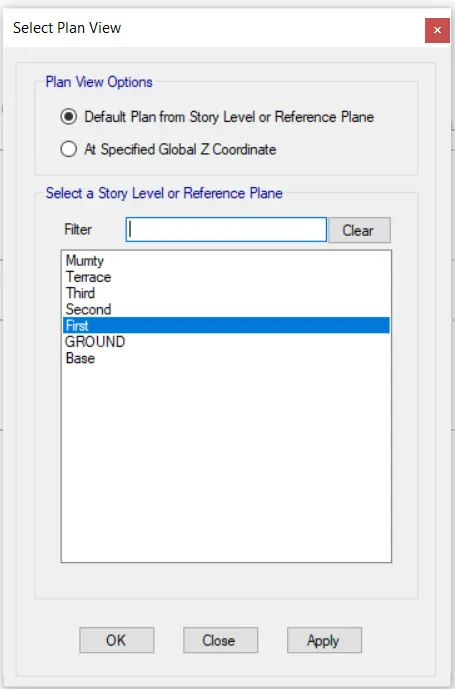
- click on APPLY and then OK .
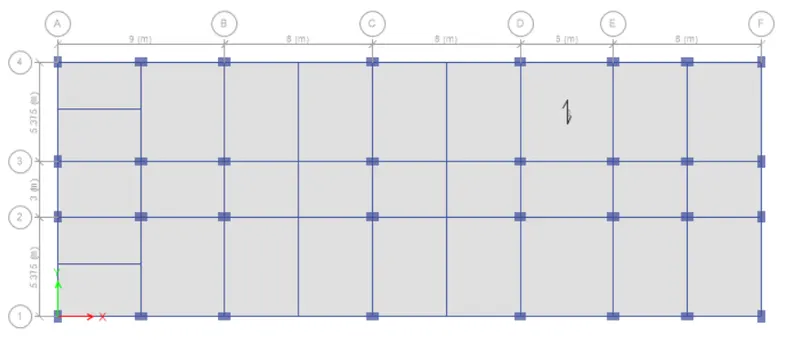
- STEP 3
- RUN ANALYSYS :
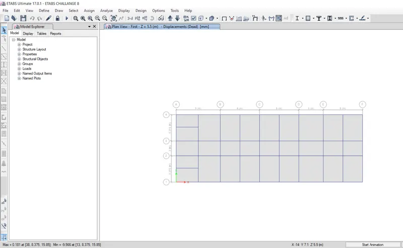
- After analysis got completed then we get maximum and minimum deflection at bottom size left cornor shown in above picture .
- STEP 4
- CLICK ON CONCRETE FRAME DESIGN TAB
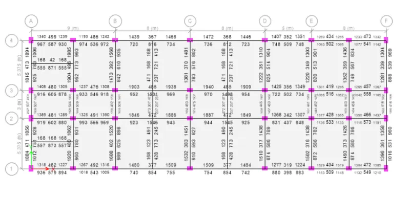
- STEP 5
- CHECK THE SHERE RENFORCING :
- So that click on Concrete frame design dropdown
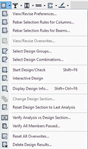
- click on Display Design Info tab
- then again new dialogbox is open
- shown below
- select the share reinforcing option
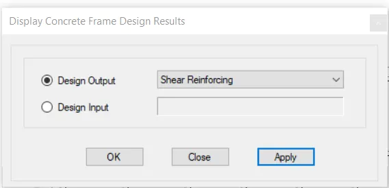
- click on APPLY and then click ok
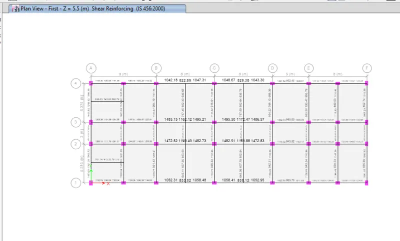
- STEP 6
- CHECK THE DETAILS OF PERTICULAR ELEMENT
- So that, rignt click on any element
- then one dialogbox is open
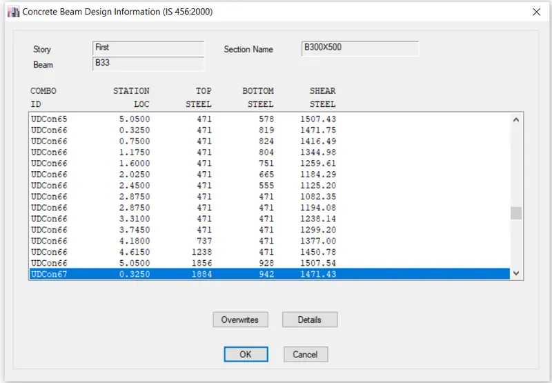
- click on Details tab
- click on Shear details
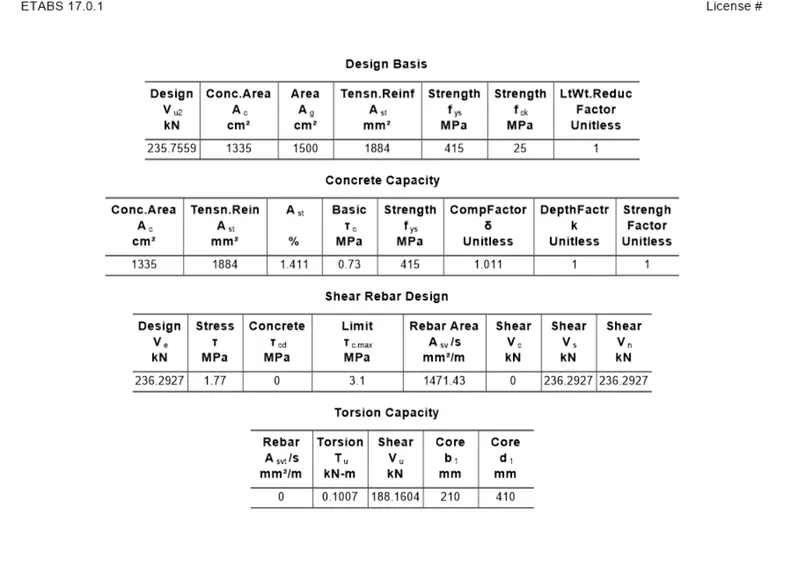
-
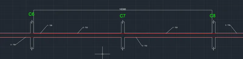
Reinforcement details along Grid A
- Max Ast at bottom support =1927mm²
- Max Ast at Top support = 2027 mm²
- Reinforcement Calculation
- For Top & Bottom Max Ast is 2027 and 1927 mm2
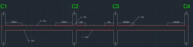
- So we can provide 2 bars of diameter 32 mm and
- Additional bar of 25 mm diameter to satisfies the overall Ast
- 2 x T32 = 1608 mm²
- 1 x T25 = 490 mm² ................... Hence Satisfy
- 2 x T32 = 1608 mm²
- 1 x T25 = 490 mm² ................... Hence Satisfy.
-
For Shear details
- Right Click on Beam and Click on Details
- Click on Shear Details
- As per Clause 6.3.3 we have to provide Spacing till 2d from the face of the column is 100.
- It should not be more than that
- So provide 3 legged stirrups of 10mm diameter with 100mm spacing throught the beam length.
- STEP 7
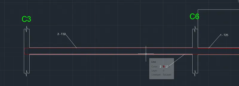
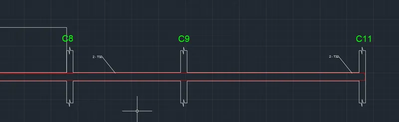
- Reinforcement details along Grid 3
- Max A, at bottom support = 1501 mm²
- Max At at Top support = 1940 mm²
- Reinforcement Calculation
- For Top & Bottom Max Ast is 1940 and 1501 mm2
- So we can provide 2 bars of diameter 32 mm and
- Additional 1 bars of 25 mm at top to satisfies the overall Ast
- 2 x T32 = 1608 mm²
- 1 x T25 = 490 mm² ...............Hence Satisfy.
- For Shear details
- Right Click on and Click on Details
- Click on Shear Details
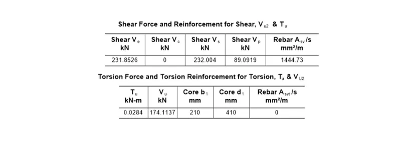
- As per Clause 6.3.3 we have to provide Spacing till 2d from the face of the column is 100.
- It should not be more than that
- so provide 3 legged stirrups of 8mm diameter with 100mm spacing throughout the beam length.

- STEP 8
- Now we have to do Check for Sway shear.
- A] For Right Sway
- We know that the formula to calcuate
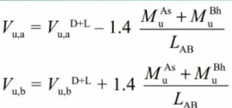
- From Etabs Model results substitute the value -
- VuD+L =92 Kn
- Mas = 176 kn.m
- Mbh = 295 kn
- Lab = 4.725 m
- Put this value in above eqn we get,
- Vu,a = 48 Kn
- Vu,b = 230 Kn
-
B] For Left Sway
-
Follow the same process
-
We know the formula
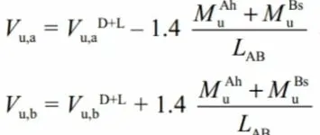
- From Etabs Model results substitute the value
- VuD+L = 74 Kn
- Mah = 236 kn
- Mbh = 150 kn
- Lab = 4.725 m
- Put this value in above eqn we get,
- Vu,a = 190 Kn
- Vu,b = 50 Kn
- C] Existing Shear capacity in beam as per Is 456-2002
- We know the formula
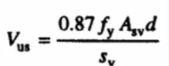
- Put the values
- Fy = 415 N/mm2
- Asv =151 mm2
- Spacing = 100 mm
- d = 450 mm
- put this value in above equection , we get
- Vus) = 246 … > 230 kn (Shear sway) .............(Hence Safe)
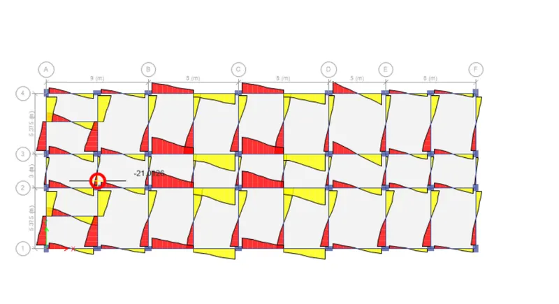
- Results
- Beam Design is done successfully with detailed reinforcement.
- Provide reasons for failure of the middle span along grid A. What are the possible ways this issue can be resolved?
- a. The main reason of failure of middle span along grid A is shear stress is exceeded the limiting value
- b. This may be because of the higher Shear force acting on that beam and due to provision of weak shear reinforcement at the end support
- This Issue can be solved by
-
By providing Higher grade of concrete in that particular section
- Or by reducing the Shear force in that beam section
- or by providing higher shear reinforcement which can resist the shear force in that section
- Calculate value of the maximum shear force in any one of the spans in both the continuous beams, as per clause 6.3.3 (b) in IS 13920 2016.
- As we have already calculated the value of shear force as per IS 13920 - 2016 Clause 6.3.3 (b)
- We get the Shear sway value Right and Left support within limit
-
246 kn > 230 kn................... Safe).