Reinforcement Detailing of Beams from ETABS output
Aim:
The project's goal is to analyse the provided work and extract the details drawings for the specified beams in 2 grid lines that are both vertical and horizontal.
Additionally, to examine and redesign the faulty RC Beam
Analyse and Design of RC Beam:
Step:1-Model Check
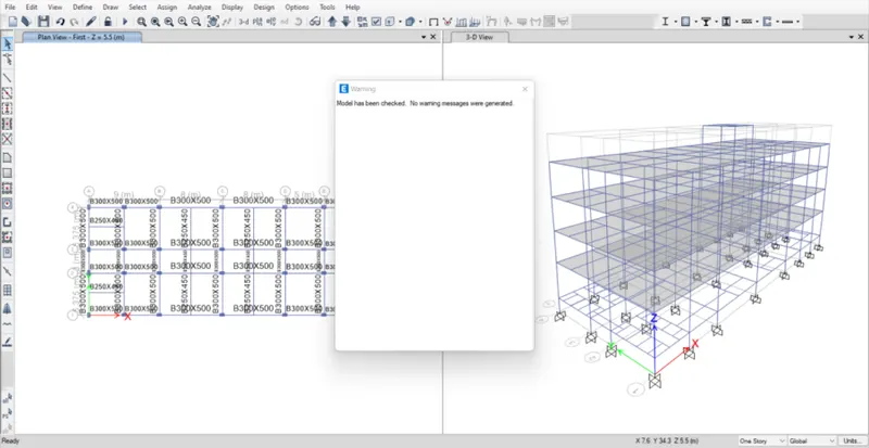
Analyze > Check Model
Analyze > Run Model
The provided model is review, model checked using above methods and then performed analysis for results extraction.
Step:2
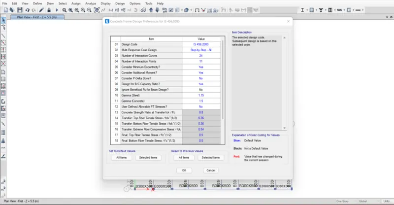
Design > Concrete frame design >View/Revise Preference
The standard IS design reference is updated for detailed design of the structural elements.
Step:3
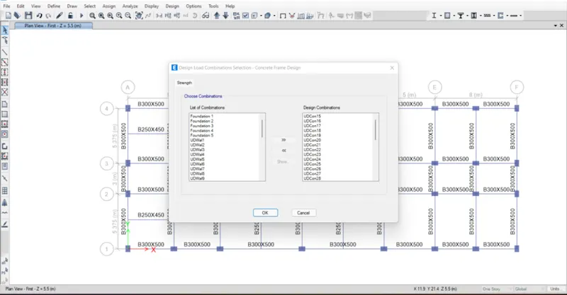
Design > Concrete frame design >Select design combination
Design > Concrete frame design >Start design/check.
After confirming the codal standards, covers and design combinations, the etabs model design of RC elements initiated.
Step:4
Longitudinal reinforcement:
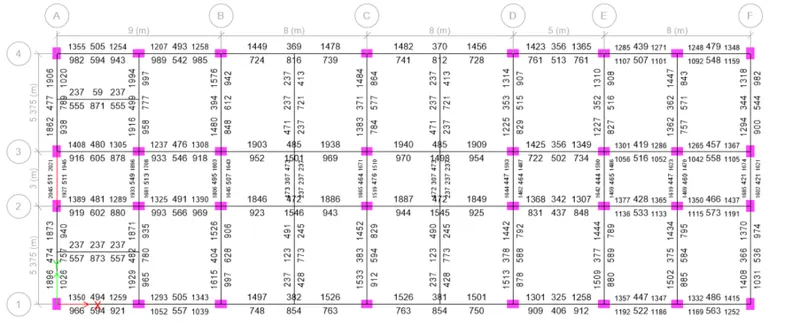
Design > Concrete frame design >Display Design info > Longitudinal reif.
Shear details:
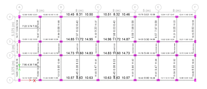
Design > Concrete frame design >Display Design info > Shear reif.
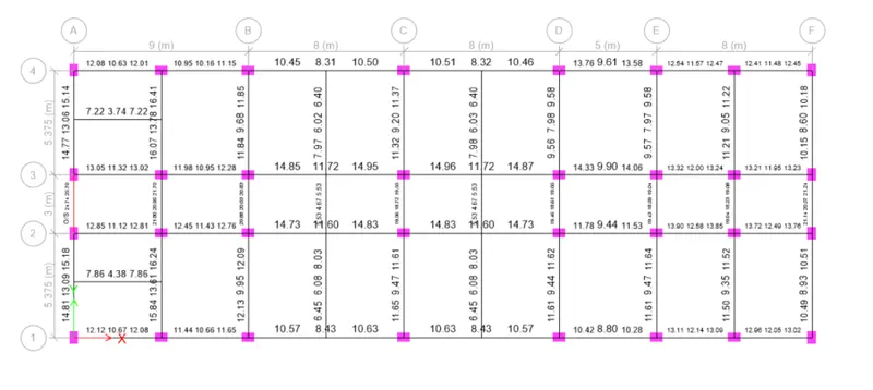
For the required Beams in X& Y direction the Beam reinforcement details are extracted separately for better understanding,
For 7 Span System:
Longitudinal Reinforcement:

Shear Reinforcement:

Vertical 3-Span System:
Longitudinal Reinforcement:
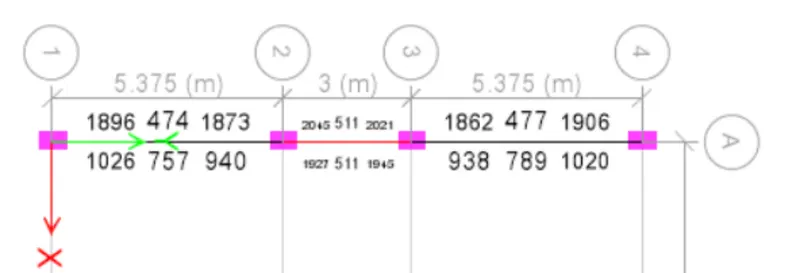
Shear Reinforcement:
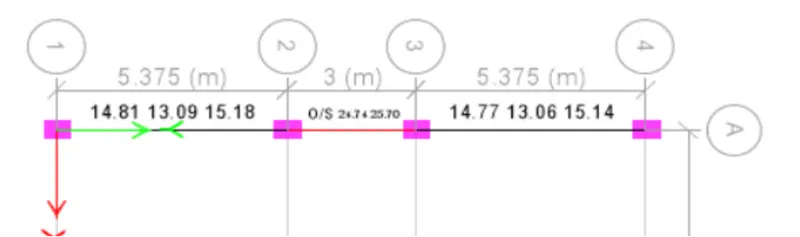
Step:4
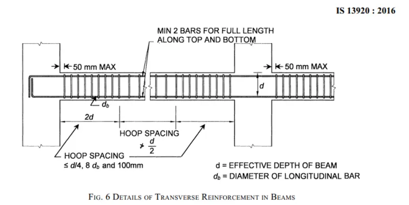
In reference to the IS Code -13920-2016, all the detailing standards are followed and Beam details are drafted in Autocad.
Checking the Beam failure at Mid span at Vertical GL-A:
Extracting the beam details
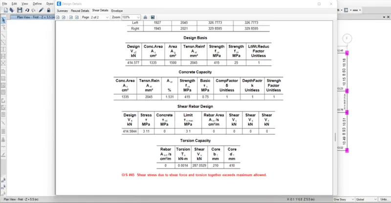
From the above detailed review, the stress values of the mid span of the beam in GL-A is failing due to exceeding of the design stress value.
This Failure can be resolved by,
- Providing additional reinforcement for excessive stress.
- Increase of the concrete grade increases the allowable stress limits.
- Reduction in depth of RC reduce the stiffness & Flexure requirements.
Calculation of Design Shear Force manually for the RC Beams with reference of IS-13920-2016, Clause 6.3.2:
Moment capacity of the reinforcement provided:
Grid-A RC Beam:
With reference to IS 456-2000-Annexure-G,
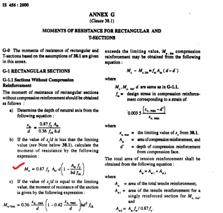
Reinforcement at support Top –
Reinforcement at Support bottom-
The moment capacity for the provided reinforcement is determined.
Hogging moment Capacity of Beam =
Sagging moment Capacity of Beam=
The shear force considered for the sway shear calculation is the shear force obtained from the Load Combination 1.2(DL+LL).
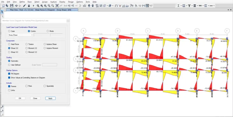
Shear force for the 1.2(DL+LL) , Demand Shear Force=
Clear Span Lab=7.365m
- For sway to right,
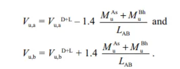
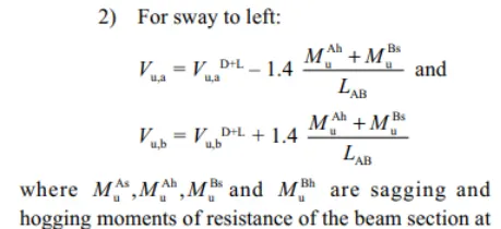
Using the above equations provided in Indian Code ,13920-2016-Clause-6.3.3,
Sway to right shear =
Sway to left shear =
As per calculation required shear reinforcement =
As drawing, Provided shear reinforcement =
Provided shear reinf. > Calculated shear reinf required
Hence ok.
Conclusion:
By using the Indian standard Beam reinforcement is detailed with ductility requirements and the sway shear capacity is manually calculated.
And also, the midspan in RC Beam in vertical Grid-A is investigated and the correction to be done in size is suggested.