Reinforcement Detailing of Beams from ETABS output
AIM:
Detail design of beams in Etabs 2018.
The ETABS file for a G+4 building is provided. Run the analysis and design the RCC Moment ResistingFrame. The following challenge deals specifically with two continuous beams in the 1st floor.
1) 3 span continuous beam along grid A
2) 7 span continuous beam along grid 3
Address the following issues thereafter.
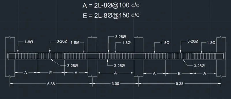
Provide details of longitudinal and shear reinforcement for the two continuous beams. Sketch the beam elevation details or draft it using autocad software. A sample of how beam elevation details is prepared in consultancy firms is provided below. Participants can prepare it as per their preference:
Provide reasons for failure of the middle span along grid A. What are the possible ways this issue can be resolved?
Calculate value of the maximum shear force in any one of the spans in both the continuous beams, as per clause 6.3.3 (b) in IS 13920 – 2016. Also, confirm these values from shear force demand calculated by ETABS.Please note that if longitudinal reinforcement provided is more than required (as per ETABS results), the shear force demand will vary from what is provided by ETABS.
INTRODUCTION:
Reinforced concrete beams are structural elements that designed to carry transverse external loads. The loads cause bending moment, shear forces and in some cases torsion across their length. Moreover, concrete is strong in compression and very weak in tension. Thus, Steel reinforcement used to take up tensile stresses in reinforced concrete beams. Furthermore, beams support the loads from slabs, other beams, walls, and columns. They transfer the loads to the columns supporting them. Additionally, beams can be simply supported, continuous, or cantilevered. they can be designed as rectangular, square, T-shaped, and L-shaped sections. Beams can be singly reinforced or doubly reinforced. The latter are used if the depth of the beam is restricted. Finally, in this article, the design of rectangular reinforced concrete beam will be presented.
PROCEDURE:
Open the downloaded file in Etabs
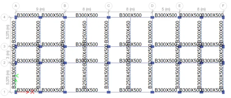
Select All stories ,select the column right click & press the show selected objects only
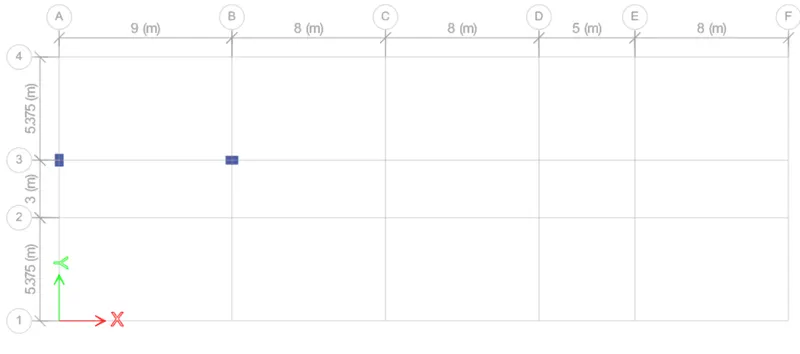
Select 3d view & run analysis
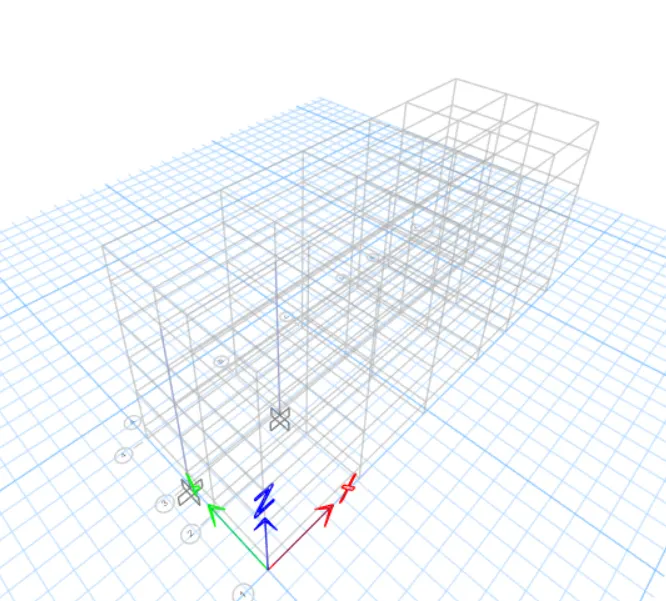
Click concrete frame design
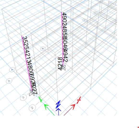
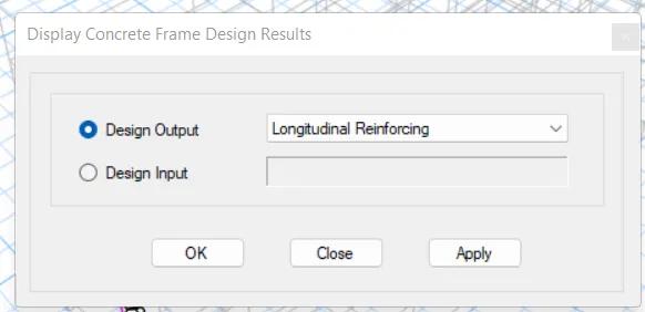
Go to concrete frame design>display design info>longitudnal reinforcement>apply.
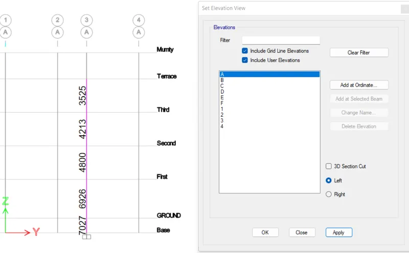
Go to elevation >grid A>apply
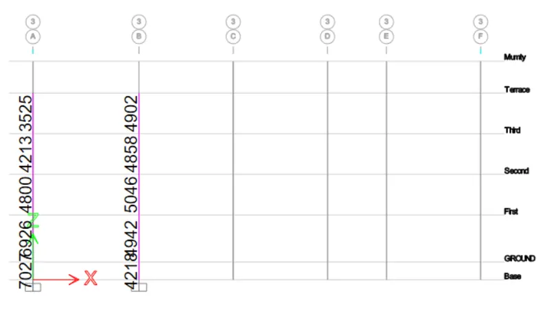
Click grid 3 >display design info>shear reinforcement>apply
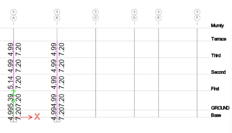
Go to concrete frame design>display design info>shear reinforcement>apply.
Go to edit>edit storey & grid system>modify system data
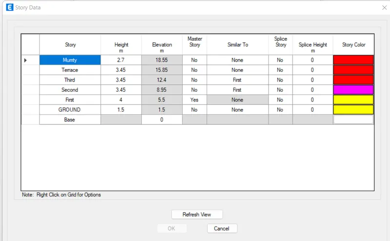
Longitudnal & shear reinforcement of column at grid 3B from ETABS (450*650)
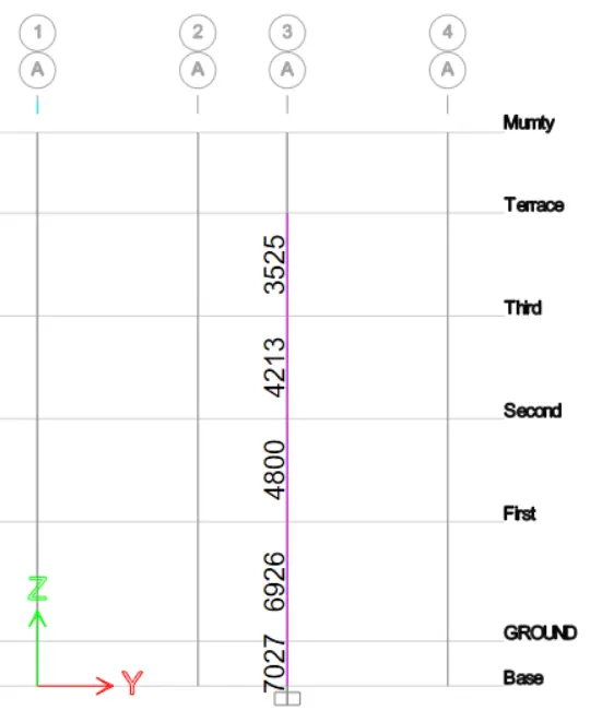
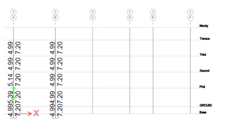
Beam elevation deatils using AUTOCAD
After providing beam reinforcement details,select the beam & right click the beam new tab appears
Click on the details concrete frame design information appears.
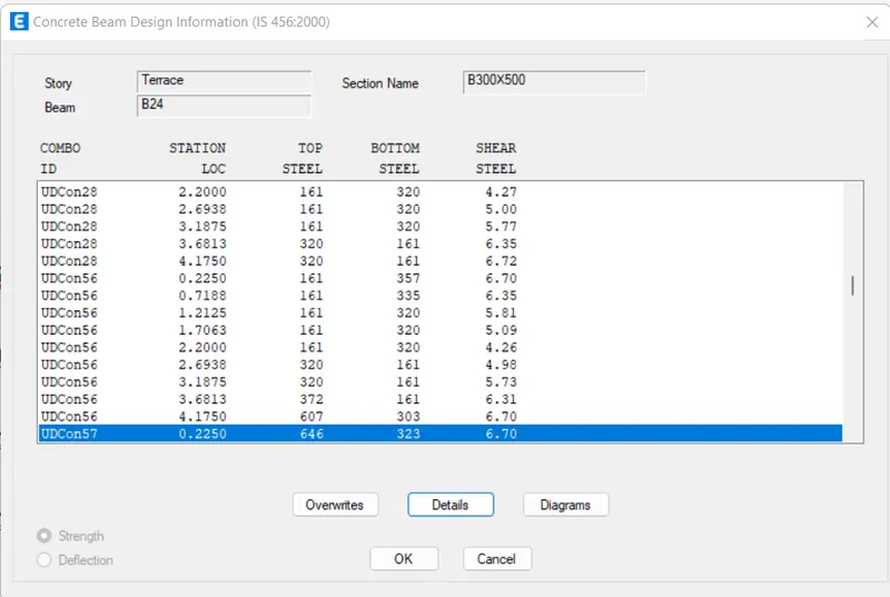
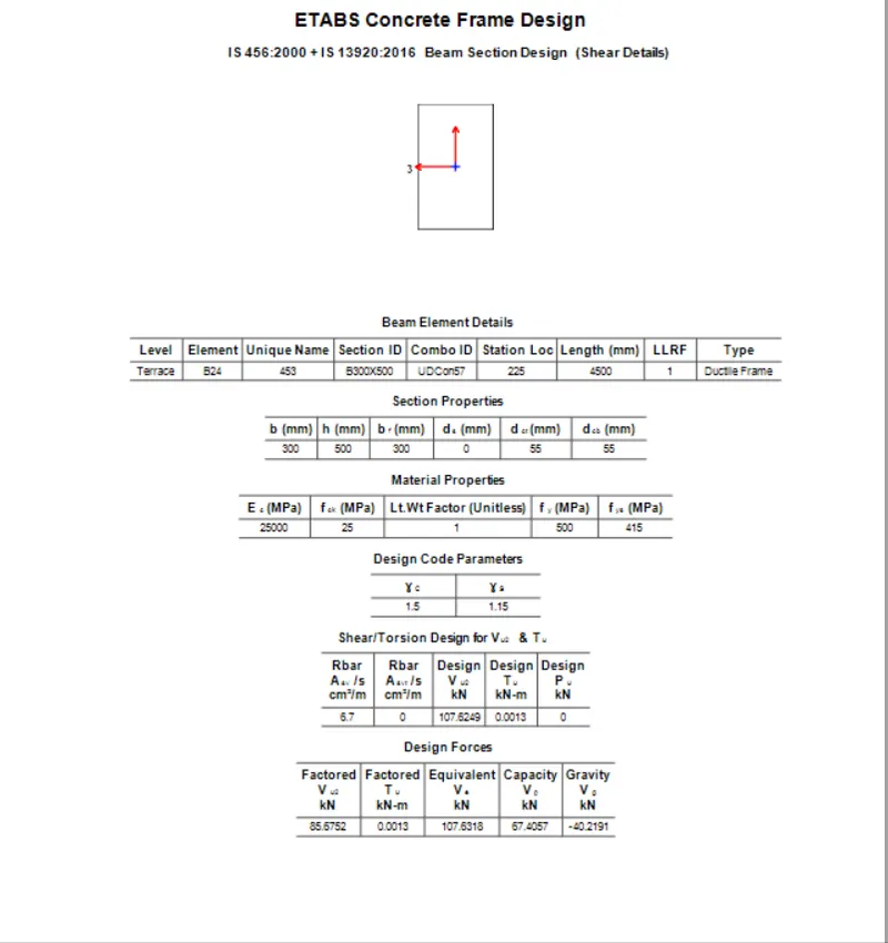
As per clause 6.3.3 design shear force will be 107.62KN
Maximum shear force =85.67KN
RESULT:
The beams are designed successfully in detail from the Etabs software.
Provided the details of longitudinal and shear reinforcement for the two continuous beams.
And also calculated the value of maximum shear force in the continuous beams using the Etabs software.
As per clause 6.3.3 design shear force will be 107.62KN
Maximum shear force =85.67KN