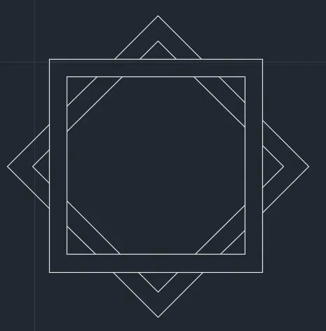
Drafting of various geometries using Chamfer, Fillet tool in AutoCad
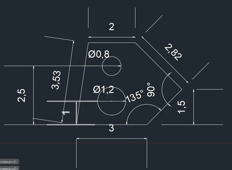
1)AIM:
To draw the given diagram using Autocad.
PROCEDURE:
Step 1:
Type units in command section select decimal ,precisions & give ok.
Start trhe point with the coordinates(0,0)
In the command section type @3<0
In the command section type @2.12<45
In the command section type @2.83<135
In the command section type @2<180
Type close in the command section & undo
Step 2:
Select the object snap icon
Click on endpoint,endpoint
Select the midpoint of the line dimension 3
Turn on the orthomode
From the midpoint draw a line of @1<90
Turn off ortho mode
From the end of the line draw a circle of dia 1.2 by selecting circle tool, option centre to dia
Delete 1<90 line
Step 3:
Draw a line of @2.5<90 from the midpoint of the line dimension 3
From the end point of the line draw a circle of dia 0.8 by selecting circle tool ,option centre to dia
Delete 2.5<90 line
RESULT:
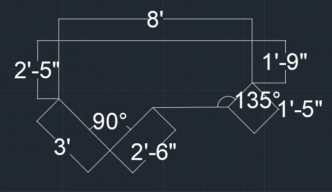
2)AIM:
To draw the given diagram using autocad software.
PROCEDURE:
Type units in the command section units>type>Architectural>precision>0'-0"
Draw a horizontal line of length 8'-0"
From left end draw a line of command @2'-5"<270
In command section type @3'-0"<135
In command section type @ 2'-6"<45
From right end of the line 8'-0" draw a line dimension in command section @1'-9"<270
In command section type @1'-5"<225
close the end line
RESULT:
3)AIM:
To draw the given diagram using Autocad software.
PROCEDURE:
In the command section type units>Type>Architectural>precision>0'-0"
Draw a line of length 2'-6.5" at angle 0
From left end of the line 2'-6.5" draw a line of 3'-3.0" at angle 270
Draw a line of distance 5' at angle 0
Draw a line of distance 1'-6" at 90
close the line
Draw a circle of dia 1'-6"
RESULT:
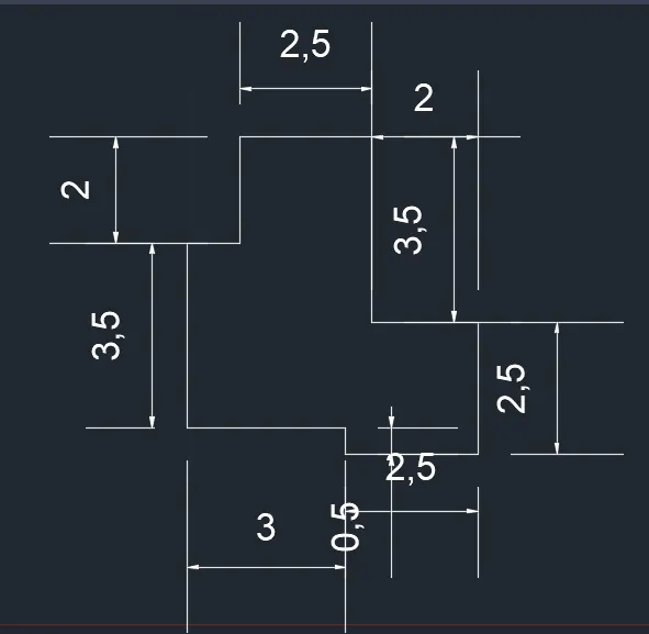
4)AIM:
To draw the given diagram using Autocad.
PROCEDURE:
Select the coordinates
From the coordinates draw a line of sitance 3 towards right side
Move the courser towards downward and draw a line of distance 0.5
Move the courser towards right side and draw a line of distance 2.5
Move the courser towards upward and draw a line of distance 2.5
Move the courser towards left and draw a line of distance 2.0
Move the courser towards upward and draw a line of distance 3.5
Move the courser towards left and draw a line of distance 2.5
Move the courser downward and draw a line of distance 2
Move the courser towards left and draw a line of distance 1.0
Move the courser towards downward and draw a line of distance 3.5
RESULT:
5)AIM:
To draw the given diagram using Autocad.
PROCEDURE:
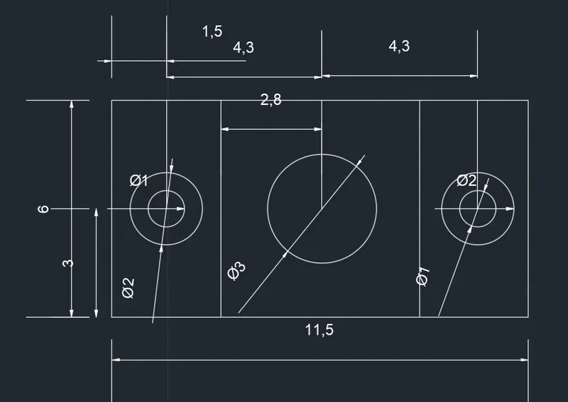
Draw a line of distance 6 towards downward
Draw a line of ditance 11.5 towards right from the end point of previous line
Draw a line of distance 6 towards upward from the end point
Draw a line of distance 11.5 towards left from the end point of previous line
Offset of line distance 6 to a distance of 1.5
Offset of line 11.5 to a distance of 3
From the intersection of the two offset lines draw a circle of dia 1& dia 2
Offset the line of length 6 to a diance of 5.8
From the midpoint of that line draw a circle of dia 3
Now repeat the same procedure from the right end
Offset of line distance 6 to a distance of 1.5
Offset of line 11.5 to a distance of 3
From the intersection of the two offset lines draw a circle of dia 1& dia 2
RESULT:
6)AIM:
To draw given diagram using Autocad.
PROCEDURE:
D1:
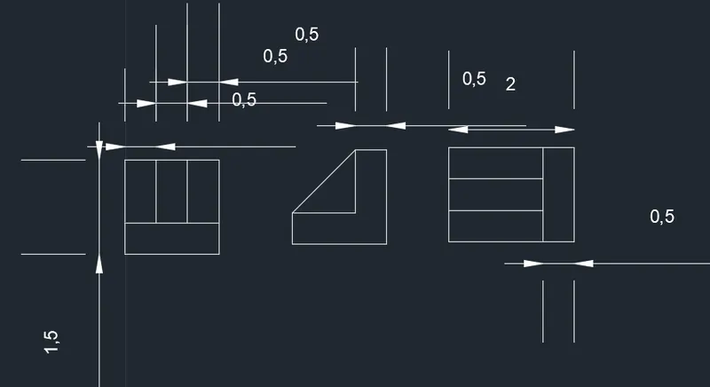
Draw a line of distance 1
Offset the draw line 3 times to a distance of 0.5
Join every edge of the line
Offset the bottom edge line to a distance of 0.5
D2:
Draw a line of distance 1.5
From both the edge of the 1.5 draw a line of distance 0.5
From bottom end of the line 0.5 draw a line of distance 1 towards downward
Now from the end draw a line of distance 1 and connect
D3:
Draw a straight line of distance 1.5 & from that line end draw a line of 0.5
Now from the 0.5 line end draw a line of distance 1.5 towards downward
Now offset the 1.5 towards left to a distance 0.5
Offset the line 1.5 to a distance 0.5
Now connect end point of every line
RESULT:
7)AIM:
To draw the given diagram using Autocad.
PROCEDURE:
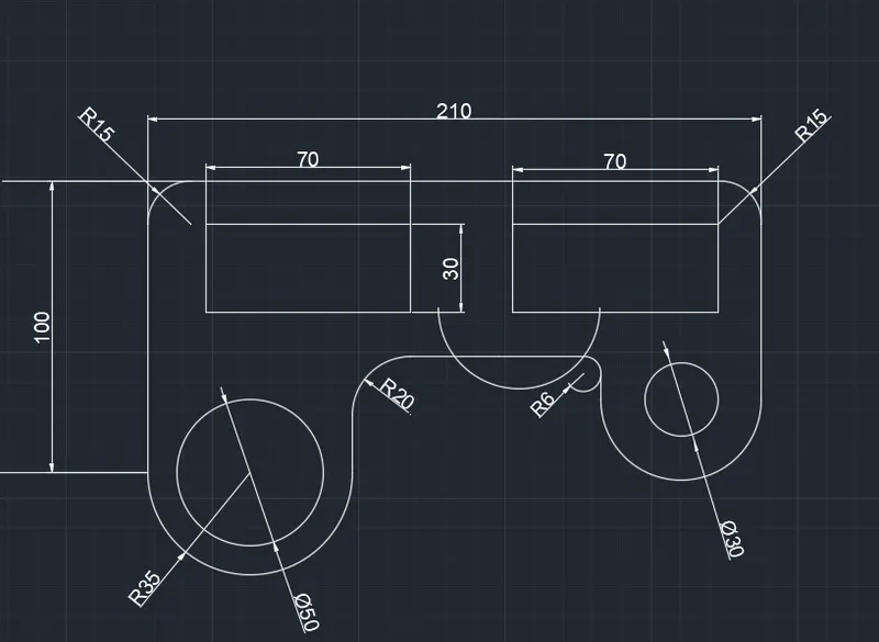
Draw a vertical line of distance 100
From top end of the line draw a horizontal line of distance 210
From 210 line end draw a vertical line of length 75
From end of the line 100 draw an arc byv selecting option start ,end , radius
Draw an arc of radius 25
Draw a horizontal line of distance 70 from end of the line 100
From midpoint of line 70 draw a circle of dia 50 ,now after drawn the circle delete the line
From the end point of the line 75 now draw a horizontal line 65 from the midpoint draw a circle of dia 30 & after drawn the circle now delete the line
From the end point of the line 75 now draaw an arc of radius R25
using fillet option change the corners to R20 & R6
From both top corners draw a rectangle of length 70 & breadth 30 which is 20 away from horizontal axis & 10 away from vertical axis
RESULT:
8)AIM:
To draw the given diagram using Autocad.
PROCEDURE:
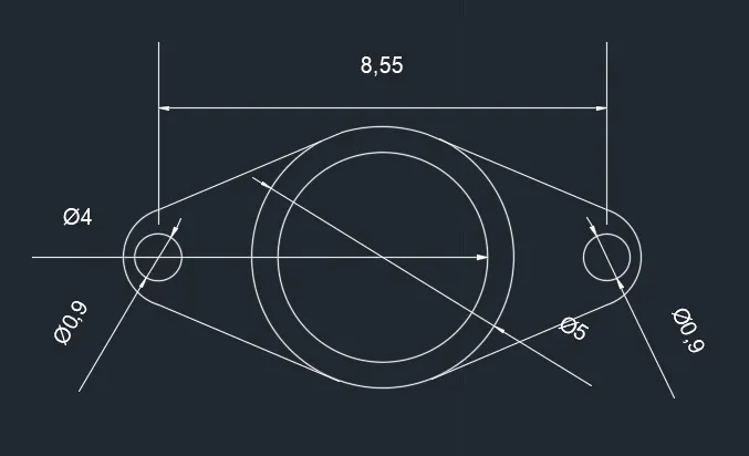
Draw the line to a length of 8.55
From both end of the line 8.55 draw a circle of dia 0.9
From the midpoint of the line 8.55 draw a circle of dia 4 & from the same midpoint draw a circle of dia 5
Create an arc of radius 0.90 at the both the ends of the line 8.55
Join the tangents of the outer circle using line & trim the extras
RESULT:
9)AIM:
To draw the given diagram using Autocad software
PROCEDURE:
Draw a line of 32'-6"
From left end of the line draw a circle of radius 8
From right end of the line draw a circle of radius 9
Draw a arc of 41'-8"
Draw a arc of 20'-10"
connect the arcs & trim the unwanted parts
RESULT:
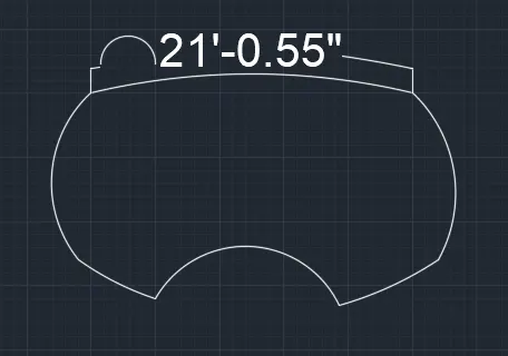
10)AIM:
To draw the given diagram using Autocad software.
PR0CEDURE:
Draw a square of same length & width
Draw another square bigger than previous one
Copy the drawn square & rotate it to 45 deg and place on the previous drawn square
Trim the extra parts
RESULT: