Creating a Floor plan, Footing detail and Isometric view using AutoCad
1)AIM:
To create C.S of load bearing wall over spread footing.
PROCEDURE:
Spread footing:
Spread footing is a type of the shallow foundation. It is defined as the structural members used to support the column and walls as well as transmit and distribute the load coming on the structure to the soil beneath it
starting initial points at (0,0)
1st point at x axis dimension 0.90
2nd point at y axis dim 0.25
3rd point from 2nd point ending 0.20 towards x axis
4th point 0.50 towards x axix
6th point 0.20 towards x axix
7th points 0.25 towards downward direction
now the rectangle of length 0.90 & width 0.25 is created
8th from the left corner of rectangle at the end of line 0.20 draw a line towards upward direction of 0.40
9th now towards right side draw a line of 0.05
10th point draw a line of 0.40 upwards ,from that end draw a line of 0.05 towards right side
now from the right corner repeat the same 9th & 10th point procedure
11th point draw line of 0.30 to connect each ends
12th now from the left corner start to draw a line of 0.60 towards upward from 0.05 line end
13th point now draw a line of thickness 0.05 towards upward
14th point now draw a line of 1 towards upward
now from the right corner line 0.05 end repeat the 12,13& 134th point
Now specify the dimension of each line drawn using dimension style
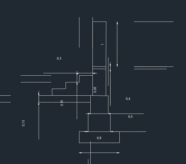
C.S OF LOAD BEARING WALL OVER SPREAD FOOTING
2)AIM:
To create c.s isolated footing.
PROCEDURE:
An isolated footing is one of the most used types of foundation to support single-columns when they are arranged at a long distance. An isolated footing must be designed to avoid exceeding its bearing capacity and provide safety against overturning or sliding while preventing the ground from settling
use polyline or line option to draw a line
1st point create a coordinates of (0,0)
2nd point draw a line of distance @1,0
3rd point draw a line of @0,0.15 from left corner of line
4th point draw a line of @0,0.15 from right corner of line
5th point draw a line of @0.38,0 from left corner
6th point draw a line of @-0.38,0 from right corner
7th point now use chamfer option for slanding line
8th point draw a line of @0,1.60 from left corner
9th point draw a line of @0,1.60 from left corner
now use close option to connect top 2 ends
10th point from the left corner to the distance of 0.04 draw a line of distance 2 towards downward direction
11th point from the right corner to the distance of 0.04 draw a line of distance 2 towards downward direction
12th point draw a line of distance 0.38 towards left side
13th point draw a line of distance 0.38 towards right side
14th point create offset of line 0.24 to a distance of 0.20
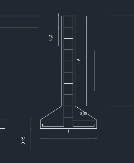
C.S OF ISOLATED FOOTING
3)AIM:
To create a line diagram of two bedroom building.
PROCEDURE:
use rectangle option or command section to create a rectangle of dimension 3.6*3.6,3.6*4.2
use offset option to create a offset of line 1 to the offset distance of 0.30
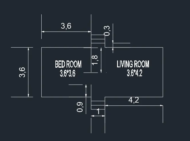
LINE DIAGRAM OF A TWO BEDROOM BUILDING
4)AIM:
c.s of load bearing walls showing foundation details.
PROCEDURE:
1st point draw a rectabgle of 0.45*0.90
2nd point from top left corner at a distance 0.15 draw line of distance 0.40
3rd point draw a line of 0.05 & draw a line of distance 0.30 towards upward direction
4th point draw a line of 0.05 & draw a line of distance 0.60 towards upward direction
5th point draw a line of 0.05 & draw a line of distance 1 towards upward direction
Enter close option & select 2 lines top end
Repeat the same procedure from 2nd to 5th point
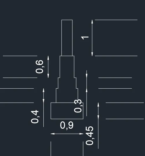
C.S OF LOAD BEARING WALL SHOWING FOUNDATION DETAILS
5)AIM:
To create isomteric view of steps
PROCEDURE:
Isometric view in computer graphics , a rendering of a 3D object that eliminates the distortion of shape created by true perspective. In isometric views, all lines on each axis are parallel to each other, and the lines do not converge. Such drawings are commonly used in technical illustrations because of their clarity, simplicity and speed of creation.
use isometric left ,isometric right & isometric top option according to the side
Type ds give enter turn off snap & grid mode ,turn on isometric option and give enter
Draw a line of distance 1 towards right
Draw a line of distance 0.15 towards upside ,turn on isometric left & give distance of 1 press enter
Draw a line of distance 0.15 towards downward direction
Draw steps width of distance 0.30
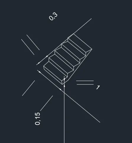
ISOMETRIC VIEW OF STEPS
6)AIM:
To create isometric view of gable wall
PROCEDURE:
Isometric view in computer graphics , a rendering of a 3D object that eliminates the distortion of shape created by true perspective. In isometric views, all lines on each axis are parallel to each other, and the lines do not converge. Such drawings are commonly used in technical illustrations because of their clarity, simplicity and speed of creation.
Type DS turn off snap & grid mode ,turn on isomtric & give enter.
use isometric left ,isometric right & isometric top option according to the side
Use line or polyline option to draw the line mentioned as per given distance
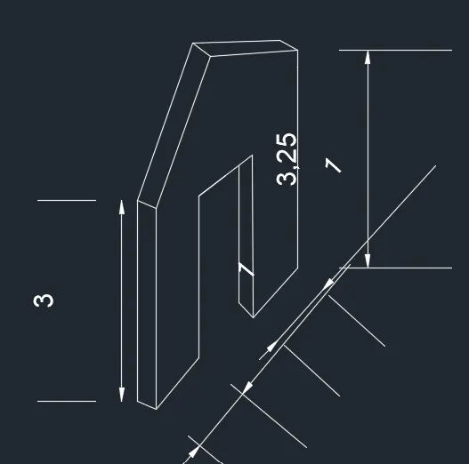
ISOMETRIC VIEW OF GABLE WALL