Reinforcement Detailing of Beams from ETABS output
AIM -
Detail design of beams in Etabs 2018.
The ETABS file for a G+4 building is provided. Run the analysis and design the RCC Moment ResistingFrame. The following challenge deals specifically with two continuous beams in the 1st floor.
1) 3 span continuous beam along grid A
2) 7 span continuous beam along grid 3
Address the following issues thereafter.
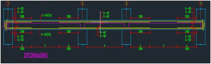
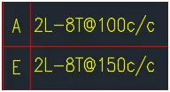
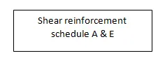
• Provide details of longitudinal and shear reinforcement for the two continuous beams. Sketch the beam elevation details or draft it using autocad software. A sample of how beam elevation details is prepared in consultancy firms is provided below. Participants can prepare it as per their preference:
• Provide reasons for failure of the middle span along grid A. What are the possible ways this issue can be resolved?
• Calculate value of the maximum shear force in any one of the spans in both the continuous beams, as per clause 6.3.3 (b) in IS 13920 – 2016. Also, confirm these values from shear force demand calculated by ETABS.Please note that if longitudinal reinforcement provided is more than required (as per ETABS results), the shear force demand will vary from what is provided by ETABS.
ANS - SELECTING A COLUMN -
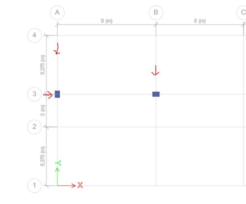
Open a Etab File To Analysis of column select a grid 3A OR 3B. after that right click and and click on selected model.
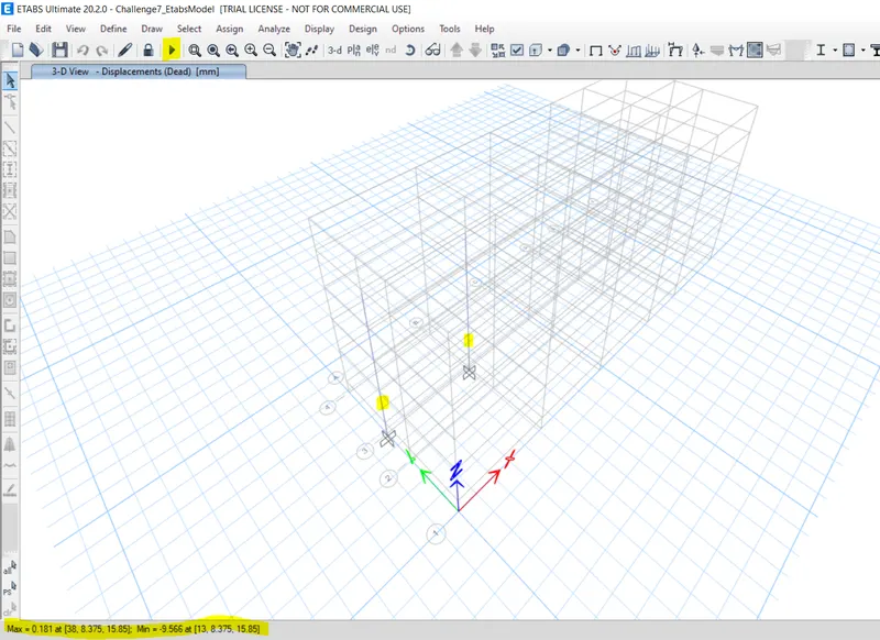
Analysing - After selection of both the column analysing. after analysing the moments are shown in bottom side.
Longitudinal Reinforcement -
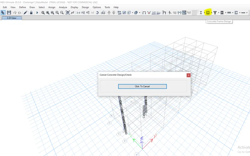
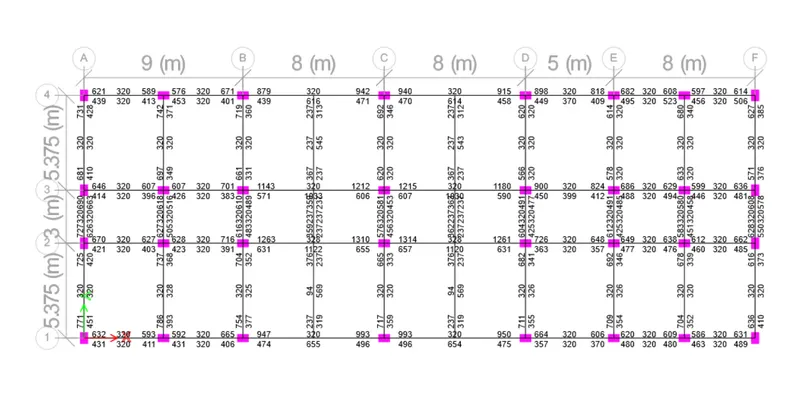
for longitudinal reinforcement details check click on concrete frame Design and start analysis of column .
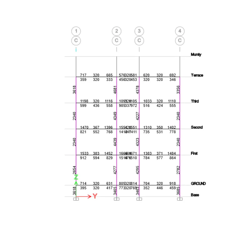
After Analysis -
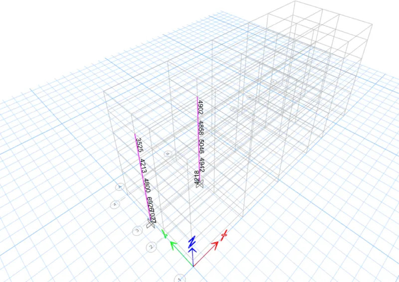
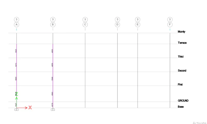
Elevation Along Grid (A) -
For Elevation Along Grid - A Click On Elevation Which Located In top Of The Ribbion. After That Click on Ok and apply it.

longitudinal Reinforcement View -
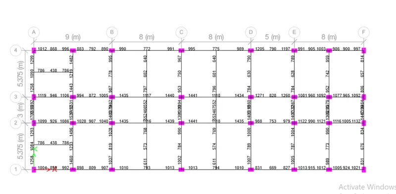
When Click On Grid -3 then both longitudanal Reinforcement is viewd.
Shear Reinforcement Check -
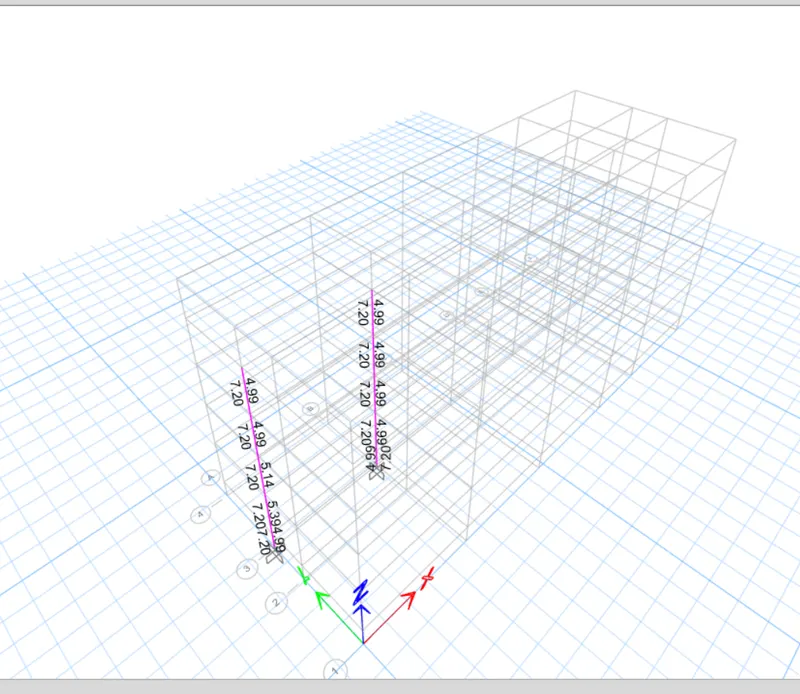
for Shear reinforcement details check click on concrete frame Design and drop down the Design button and click on Disply Design Info. and after that select sheir Reinforcement click ok.
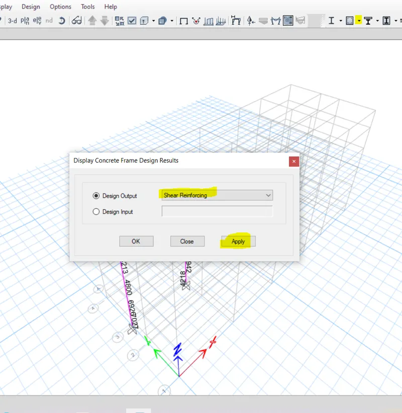
After that it shopws the 3d view like this.
Logitudinal reinforcement calculation -
longitudinal Reinforcement is calculated by -
(1000/spacing)* Area*Leangth
Area = `pi/4*d^2`
leangth - given leangth of beam or column.
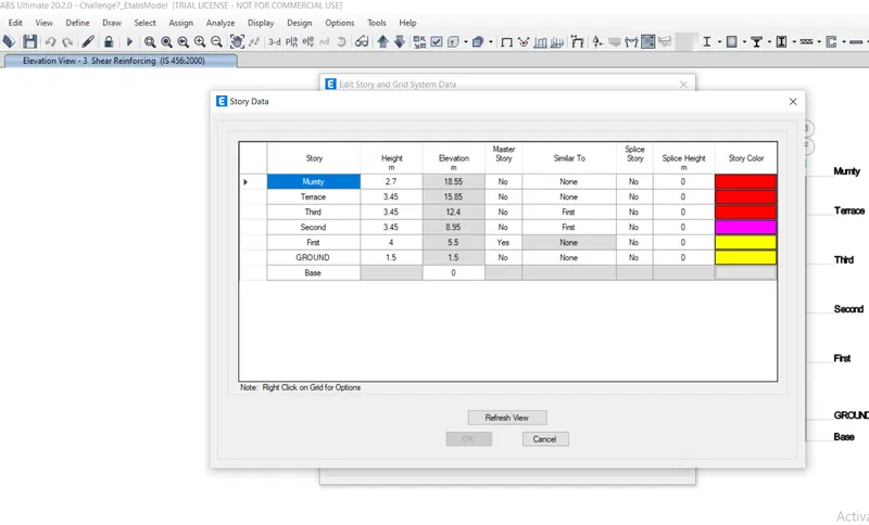
Storey Assingment Tab to Refer Elevation of Column -
It should be useful of elevation of column. and also useful to design shear and longitudinal reinforcement.
Special confining Reinforcement according to IS - 13920-2016
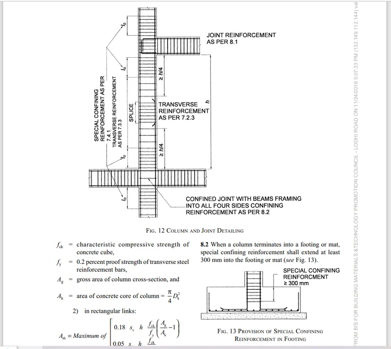
`l_0` not less then -
1. larger column dimension
2. 1/6 of clear span of column
3. 450 mm
confinment spacing is not More then
1. 1/4 of smaller column dimension
2. 6 times of dia of column main bar
3. 100 mm
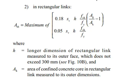
the following two formula given according to is13920 - 2016 for circuler and rectanguler column section.
Logitudinal reinforcement calculation -
longitudinal Reinforcement is calculated by -
(1000/spacing)* Area*Leangth
Area = `pi/4*d^2`
leangth - given leangth of beam or column.
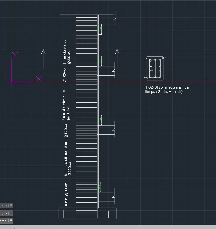
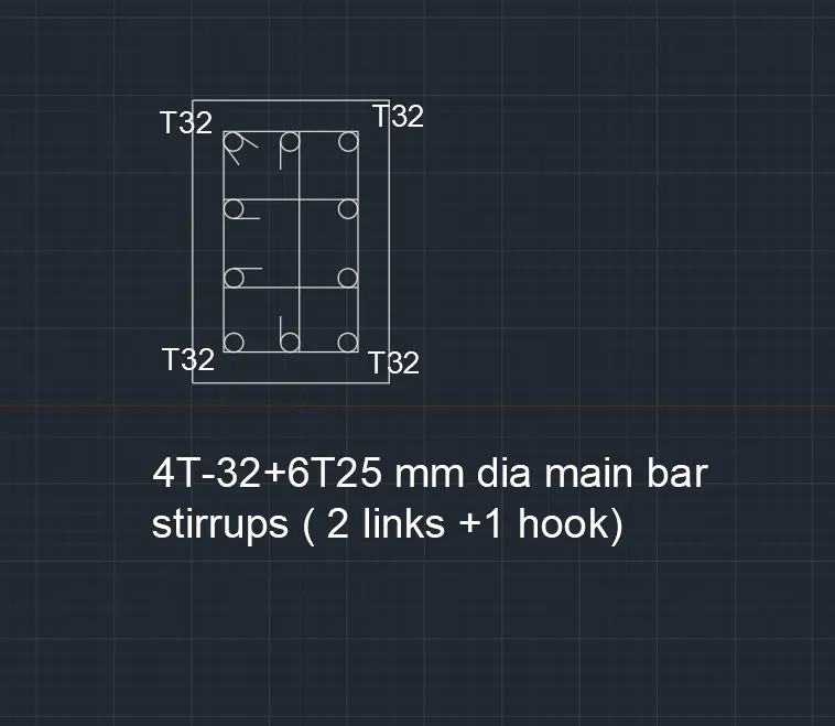
Assuming a beam having a leangth is 3m. and assuming having a area of steel is 5046 mm^2 after calculating need to satisfy the required longitudinal Reinforcement.
25 mm bars area is 490 mm^2
so providing 6 bars which having 2943 mm^2 area
Adding 4 bars ofn 32 mm having 3215.36 mm^2 area
which is fullfil the Required area of steel.
Created a design of Required steel in Autocad.
Shear Reinforcement Calculation -
Shear Reinforcement is Calculated by -
(1000/spacing)* Area*Leangth
Area = `pi/4*d^2`
Assuming,
spacing - 200mm
leangth - 3m.
steel 8mm. having area is 50 mm^2
Required Shear Reinforcement Area is - 701 mm^2.
after putting all the value getting 701 this is satisfied the required shear Rainforcement.
Showing a Reinforcement into Autocad.