Radar Mast & Final Assembly of Yacht
Radar Mast & Final Assembly of Yacht
1. Radar Mast
2. Yacht Assembly
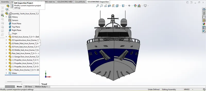
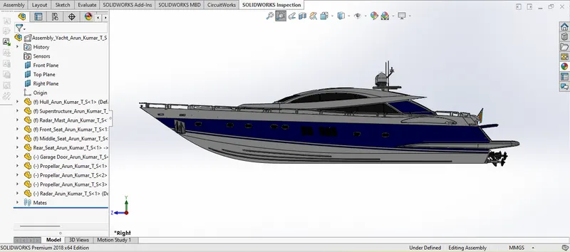
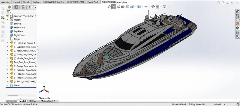
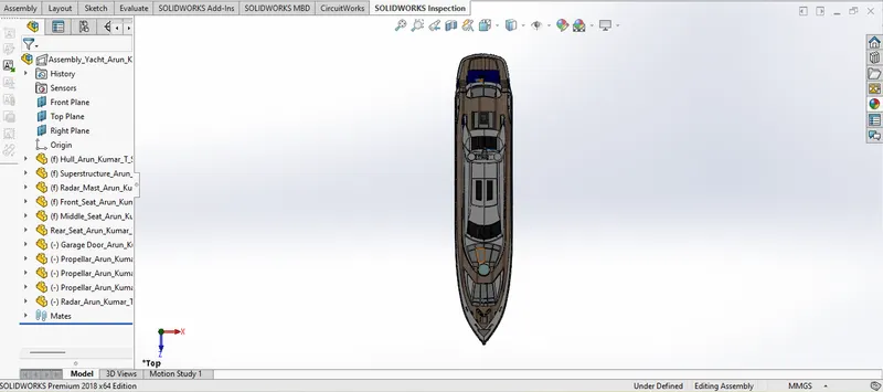
SURFACE MODELLING OF YACHT
OBJECTIVE:
- Setup of blueprints to model the parts of the yacht using surface modelling and 3d modelling.
- Creating various parts of the yacht using surface modelling.
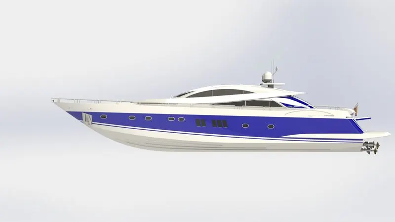
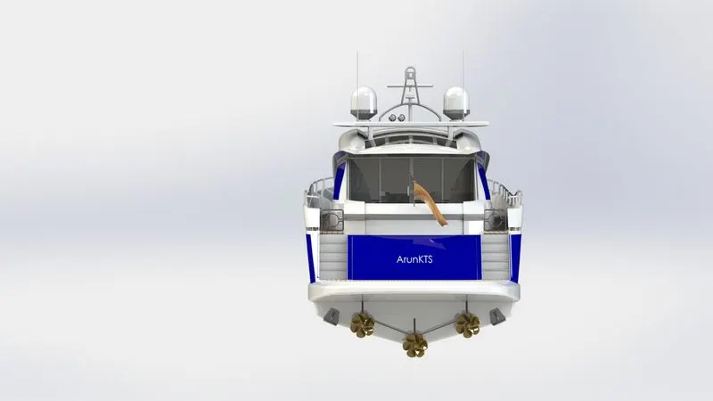
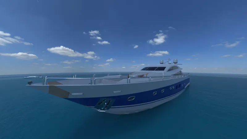
- Assemble the parts of the yacht and applying appearances, and decals to necessary parts and rendering the 3d model of Yacht in the real world like environment using Solidworks Visualize.
INTRODUCTION:
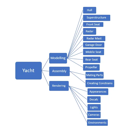
In this project, the American predator yacht was taken as a conceptual model, where we created the various parts of the yacht using Solid modelling and Surface modelling in the SOLIDWORKS®CAD software.
The SOLIDWORKS®CAD software is a mechanical design automation application that lets designers quickly sketch out ideas, experiment with features and dimensions, and produce models and detailed drawings.
The PhotoView 360 is a Solidworks Add-in that produces a photorealistic render of the part/specified region of the part, it also has the features to add/ edit appearances, lights, cameras and decals to the parts to be rendered.
The Solidworks Visualize is a rendering tool that use 3D CAD data to create photo-quality content in the fastest and easiest way and can–from images to animations, interactive web content, and immersive Virtual Reality.
METHODOLOGY:
The detailed methodologies used to model the yacht is given below.
In order to model the parts of the yacht, initially blueprint to be set up in the front view, top view, Side view and back view.
Surface Commands:
The following are the surface commands used to model the yacht.
- Lofted Surface: Creates a lofted surface between two or more profiles or sketches. By specifying start and end constraints and adding guide curves shape of the lofted path can be improved.
- Surface Trim: Trims a surface where one surface intersects with another surface, a plane, or a sketch.
- Extruded Surface: Creates an extruded surface from a sketch or selected sketch contours in one or more directions.
- Surface knit: Combines two or more adjacent and non-intersecting faces and surfaces into one.
- Filled Surface: Constructs a surface patch within a boundary specified by existing model edges, sketches or curves.
- Offset Surface: Generates a new surface body from an existing set of faces.
- Extend Surface: Extends the edge, multiple edges, or the face on a surface, based on end condition and extension type.
- Ruled Surface: It creates surfaces that extend out in a specified direction from selected edges.
- Swept Surface: Sweep Surfaces are surfaced that are generated from a section curve positioned along a path.
- Delete Face: Deletes the faces from the surface, or solid bodies.
Other Commands:
Other commands used to model the yacht were given below.
- Sketch: The sketch is a two-dimensional representation of the model to be created.
- 3D Sketch: Creates a 3D sketch with reference to XY, YZ, and ZX planes, axes, or surfaces.
- Reference Plane: It creates planes in part or assembly documents, which can be used to draw sketches, to create a section view of a model, for a neutral plane in a draft feature, and so on.
- Split Line: Projects an entity like sketch, solid, surface, face, plane, or surface spline to surfaces, or curved or planar faces. It divides a selected face into multiple separate faces.
- Project Curve: In this tool, you are going to use to form a 3D curve from two 2D curves from the two different planes.
- Extruded Boss/Base: Converting the 2D sketch/profile to a 3D profile is known as Extrude Boss/base.
- Cut-extrude: This feature is used to remove material from a 3D model using the sketched profile.
- Swept Boss/Base: This is one of the useful features, which help to sweeps a closed profile through an open or closed path.
- Revolved Boss/Base: Revolves add or remove material by revolving one or more profiles around a centreline. You can create revolved boss/bases, revolved cuts, or revolved surfaces. The revolving feature can be a solid, a thin feature, or a surface.
- Dome: Adds one or more dome-like shapes on the planar or non-planar surfaces.
- Helix/Spiral: Creates a helix or spiral curve in a part, The curve can be used as a path or guide curve for a swept feature, or a guide curve for a lofted feature.
- Linear pattern: Repeat the replica of features, faces, and bodies in one or two linear directions.
- Sketch Driven Pattern: It creates copies of existing features and places them wherever added to a point in a sketch.
- Circular Pattern: This tool allows you to create patterns along the circular path.
- Mirror: Creates a mirror body, features, and faces about a plane or face.
- Body-Delete/Keep: Using this feature, we can select the bodies to keep or delete.
- Thicken: It creates a solid feature by thickening one or more adjacent surfaces.
- Fillet: The feature used to round the sharp edges in a 3D profile/sketch.
- Chamfer: It creates the bevelled feature on the selected edges, faces or a vertex.
1. Hull
The hull of a ship is the most important as well as the most noticeable part of the ship. It is the watertight part of any vessel or even boat. It is defined as the water-tight enclosure of a ship. It protects the cargo and the machinery of the ship. It can also protect the boat from flooding and other structural damage. It is the part of the vessel which meets the ocean. The point or the line at which the hull of a ship meets the surface of the water is called the waterline.
The hull of the yacht consists of the following parts:
- Ballast – Weight in the form of heavy material (water, metal or stone) placed low in a boat hull to improve stability and performance of the boat.
- Berth – A bed or bunk if it’s in a boat or a slip for a boat to dock in.
- Bow – The front of the boat. Multihulls may have two or three bows.
- Baseline - It is a level reference line from which vertical distances are measured.
- Bow - It is the front part of the hull.
- Amidships - It is the middle portion of the vessel in the fore and aft direction.
- Port - It is the left side of the vessel when facing the bow from onboard.
- Starboard - It is the right side of the vessel when facing the bow from onboard.
- Stern - It is the rear part of the hull.
- Waterline - It is an imaginary line circumscribing the hull that matches the surface of the water when the hull is not moving.
- Railings: It is cylindrical structures made on the deck surface, which serves as fencing.
- Portholes: These are structural openings made on the hull to enter light inside the cabin below the superstructure.
- Anchor - It is a device, normally made of metal, used to secure a vessel to the bed of a body of water to prevent the craft from drifting due to wind or current.
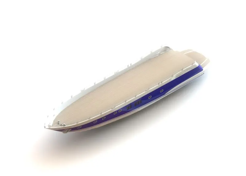
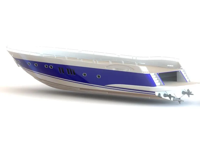
The commands used to model the hull are:
- Project Curve
- Lofted Surface
- Surface Trim
- Surface Extrude
- Surface knit
- Surface Fill
- Offset Surface
- Shell
- Sketch
- Reference Plane
- Extrude Boss/Base
- Cut-extrude
- Swept Boss/Base
- Revolved Boss/Base
- Dome
- Helix/Spiral
- Linear pattern
- Delete Face
- 3D Sketch
- Mirror
- Body-Delete/Keep
- Split Line
- Fillet
- Chamfer
The following are the procedure to model the hull:
- With reference to the side view and top view profile sketch for the hull is drawn and based on two curves, the projected curve is generated for surface loft.
- Extra surfaces are trimmed off and if there is a gap then the surface is filled.
- Now the surfaces are knitted and formed the solid.
- Using the Shell Feature, a solid body is made hollow.
- Using the Boss Extrude command, the deck surface of the hull is formed and extra surfaces are trimmed using the Cut Extrude.
- Then required Chamfers and filled are applied wherever is necessary.
- An additional plane is created parallel to the midplane and sketches are drawn on that plane.
- Using the Cut Extrude command, all the windows and portholes on the hull is created.
- Then the fillets are applied wherever required.
- For creating frames around the windows and portholes Reference Plane is created and a circle for the required dimension is made pierced and Swept command is used to form a round frame around the windows and portholes.
- At the rear end of the hull, the sketch is drawn for stairs and extruded to create the stairs.
- Necessary fillets are applied wherever required.
- On the deck surface base for cable roller is drawn and extruded.
- Cable roller is created using Revolved Boss/Base and Chamfer is applied at the top edge of it and a dome is created on its top face.
- Cable rolled in the roller is created using Helix/Spiral and Swept Boss/Base are applied.
- The Fillet is applied wherever required.
- On the deck surface, the sketch is drawn using Straight Slots and circles. Then the sketch is extruded to form the rope hanger, necessary fillets are applied and using Linear Pattern one more rope hanger is created.
- At the rear end of the deck surface, two more rope hangers are created as said in the above point.
- Using Extruded Boss/Base window bar is created.
- Handrails are created near the staircase using Swept Boss/Base.
- With the help of a blueprint, a railing reference is created and the Projected Curve is produced. Then this reference sketch is used to create railings around the hull using Swept Boss/Base.
- The light is created using Extruded Boss/Base and necessary fillets are applied.
- The surfer is created using Extruded Boss/Base, hydraulics of the surfer is created using revolved boss/base then the necessary Chamfers and Fillets are applied.
- Axels of the propeller is created using Extruded Boss/Base and Extruded Thin, then the required Fillets are applied.
- Half of the anchor is created using Extruded Boss/Base, Chamfer and the other half is mirrored. Then the necessary Fillets are applied.
- The garage portion is created by using Cut Extrude and the portion is saved for later use by using Spilt feature.
- The Split Line feature is used to paint the hull with different colours.
- Finally, another half of the hull and its parts are mirrored about the midplane to form the complete hull of the yacht.
- Now the part is saved by applying proper appearances and decals.
2. Superstructure
A superstructure is an extended construction of any building or platform that rises above the rest of the building or platform in a distinct manner. The size of the superstructure has a great influence on the mobility of the vessels. They are designed in a manner so that they add value and hinder the speed and mobility in the least. The superstructure is mostly designed in fashion as well. This is because it is the most easily visible part of the ship, in fact, it is the identification of the ship, and so the designers try to provide it with an identity that is unique.
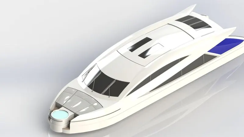
The commands used to model the superstructure is:
- Extruded Surface
- Reference Plane
- Swept Surface
- Surface Knit
- Ruled Surface
- Projected Curve
- Surface Trim
- Lofted Surface
- Filled Surface
- 3D-Sketch
- Extruded Boss/Base
- Extruded Cut
- Delete Face
- Offset Surface
- Thicken
- Dome
- Split Line
- Mirror
- Chamfer
- Fillet
The following are the procedure to model the Superstructure:
- The deck surface from the hull part is imported and the superstructure was modelled over it.
- The sidewall of the superstructure was created by Surface Extrude, Surface Sweep, Ruled Surface, Surface Trim, Lofted Surface, Filled Surface and Surface Knit.
- The top wall of the superstructure was also created by Lofted Surface, Surface Trim, Filled Surface and Surface Knit.
- The front side of the superstructure was designed to have four seats which were created by using Extruded Boss/Base, Extruded Cut, Fillets and Dome to give the realistic look.
- The front edge of the superstructure is provided with a water feature which was created using extrude boss/base and applying necessary fillets.
- At the front edge of the superstructure, stairs were created using Surface Extrude and Surface Sweep, then required Fillets are applied.
- Portholes on the superstructure were created by using Extruded Surface, Trim Surface and Extended Surface.
- Railings on the superstructure were created by drawing circles on the Reference Plane normal to curve and using Swept Boss/Base.
- Doors of the superstructure were created by Extruded cut, then door handle was created by Extruded Thin and by applying necessary Fillets.
- Now the other half of the superstructure was created using mirrors of the bodies.
- Finally, wipers were created by Extruded Boss/Base, Extruded Cut and by applying necessary Chamfers and Fillets which connected to the superstructure by drawing 3d-Sketch and extruding them.
- The necessary fillets are applied and then the desired appearances and decals were applied.
3. Front Seat
It is located in front of a superstructure which serves comfort to the passengers.
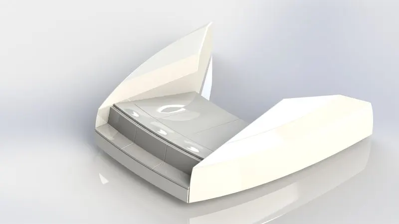
The commands used to model the Front Seat is:
- Surface Sweep
- Extruded Surface
- Lofted Surface
- Trim Surface
- Surface Fill
- Surface Knit
- Revolved Boss/Base
- Extruded Cut
- Dome
- Mirror
- Fillet
- Chamfer
The following are the procedure to model the front seat:
- The front seat is also modeled with the help of a blueprint.
- The first half of the part is created and then mirrored using the mirror tool.
- The body of the front seat was created by using Surface Sweep, Surface Extrude and Surface Loft, then the extra surfaces are trimmed off using Surface Trim and also some surfaces were closed by using Surface Fill, then all the surfaces were knitted.
- Then four rest beds are created using Revolved Boss/Base and Extruded Cut, also Domes were created over the faces of the rest beds separately.
- Then the necessary fillets and chamfer were applied.
- Finally, the part is saved by applying the desired appearances.
4. Middle Seat
It is located just behind the superstructure, along with the dining table that serves comfort to the passengers.
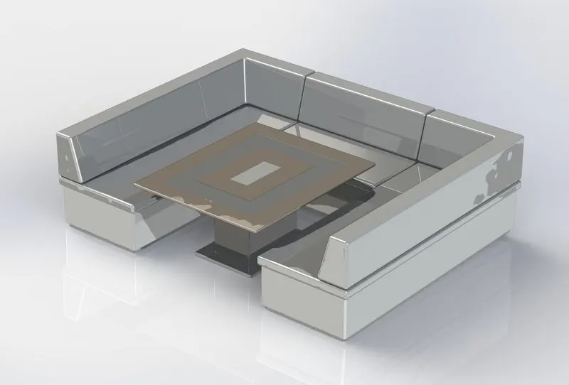
The commands used to model the Middle Seat is:
- Extruded Boss/Base
- Extruded Cut
- Reference Plane
- Mirror
- Fillet
- Chamfer
The following are the procedure to model the middle seat:
- The middle seat was also modeled with the help of Blueprint.
- The first half of the part is created and then mirrored using the Mirror tool.
- The middle seat was created by using an extruded boss/base and extruded cut.
- With the help of a reference plane, the dining table was also created by using Extruded Boss/Base, Extruded Cut, and Chamfers.
- Then the required fillets were applied.
- Finally, the part was saved by applying desired appearances.
5. Rear Seat
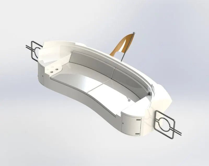
The commands used to model the Rear Seat is:
- Swept Surface
- Extruded Surface
- Offset Surface
- Lofted Surface
- Surface Trim
- Extend Surface
- Ruled Surface
- Surface knit
- Extruded Boss/Base
- Extruded Cut
- Revolved Boss/Base
- 3D-Sketch
- Reference Plane
- Swept Boss/Base
- Mirror
- Fillet
- Chamfer
The following are the procedure to model the rear seat:
- The main body of the rear seat was created by using Swept Surface, Surface Extrude, Surface Offset and Lofted Surface.
- The extra surfaces are trimmed off using Surface Trim also Surface Extend and Ruled Surface commands are used to close the surfaces and then all the surfaces are knitted using Surface Knit.
- The rest beds were created using Extruded Boss/Base and applying appropriate Chamfers and Fillets.
- The storage door on the body of the seat was created by using Extruded Cut and Extruded Boss/Base. Also, cup holders on the seat were created Extruded Cut.
- The flag post and pole were created by using Revolved Boss/Base and the flag is created by required 3d-Sketches and then these 3d-Sketch are used as profile and guide curves for Surface Loft.
- The tail lamps were created by extruded boss/base and fillets.
- The Steel gates were created by using Reference Plane and Swept Boss/Base.
- The necessary fillets were applied.
- Finally, the part was mirrored about midplane and desired appearances were applied.
6. Radar
A mandatory aid to navigation, the radar is used in identifying, tracking, and positioning vessels (including one’s own vessel) among other things in order to safely navigate a ship from one point to another. The marine radar is classified under the x-band (10 GHz) or S-band (3GHz) frequencies. The x-band, being of higher frequency, is used for a sharper image and better resolution whereas the S-band is used especially when in rain or fog as well as for identification and tracking.
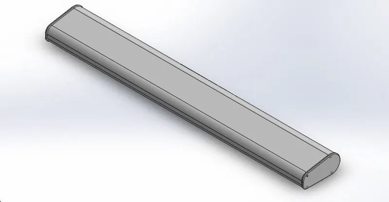
The commands used to model the Radar is:
- Extruded Boss/Base
- Extruded Cut
- Sketch Driven Pattern
- Split Line
- Fillet
The following are the procedure to model the radar:
- By drawing the required sketch on the right plane radar body was created using extruded boss/base.
- Button head bolt was created on one end of the radar using extruded boss/base, extruded cut and fillets.
- Four, button head bolts are created using a Sketch pattern at an appropriate distance from each other.
- The other half of the radar body was mirrored about the right plane using the mirror tool.
- On the bottom of the radar, a body hole was created using extruded cut.
- The text over the radar was created using the text option in the sketch and then the text was made to generate over the face using the Split Line feature.
- The sharp edges were removed by using appropriate fillets.
- Finally, the desired appearances were applied.
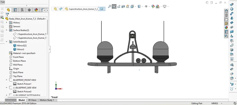
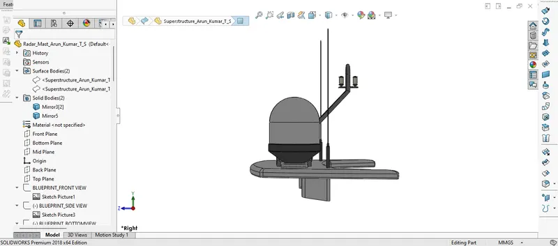
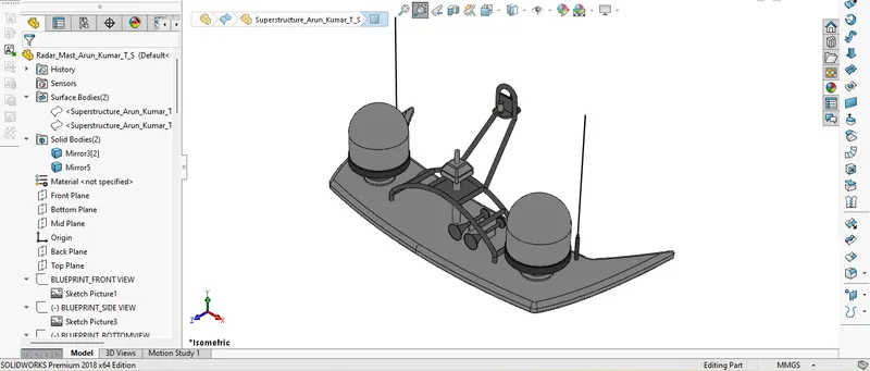
7. Radar Mast
The mast of a sailing vessel is a tall spar, or arrangement of spars, erected more or less vertically on the centre-line of a ship or boat. Its purposes include carrying sails, spars, and derricks, and giving necessary height to a navigation light, look-out position, signal yard, control position, ship horns, radio aerial or signal lamp. Large ships have several masts, with the size and configuration depending on the style of the ship.
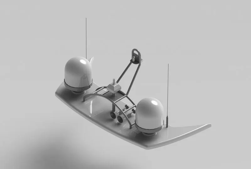
The commands used to model the Radar Mast is:
- Extruded Boss/Base
- Revolved Boss/Base
- Swept boss/Base
- Reference Plane
- Mirror
- Projected Curve
- Shell
- Chamfer
- Fillet
The following are the procedure to model the radar mast:
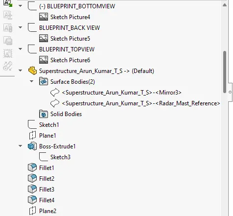
- The base of the radar mast was modeled on the surface exported from the superstructure with help of a blueprint using Extruded Boss/Base.
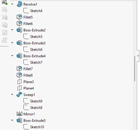
- Then the body of the radar was created using Extruded Boss/Base and Revolved Boss/Base.
- The antenna for the radar was created using extruded base/boss.
- The lampstand along with its connecting rods was created using swept boss/base and mirrored.
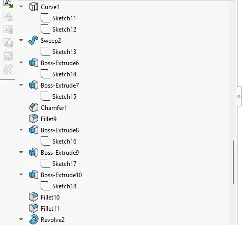
- The lamp was created using a projected curve and then it was swept by using swept boss/base.
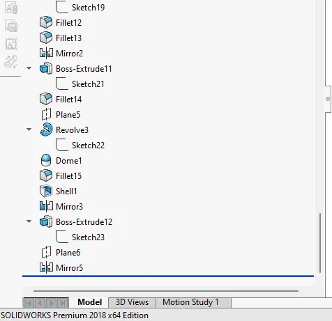
- Now the horn was modelled using revolved boss/base, extruded boss/base and shell, then mirrored using mirror tool.
- Then the necessary fillets and chamfers were applied.
- Finally, the desired appearances were applied.
8. Garage Door
The Garage door is a door on the garage in the superstructure which can be operated manually or electrically, hydraulically powered. This safely accommodates any vehicles on the yacht.
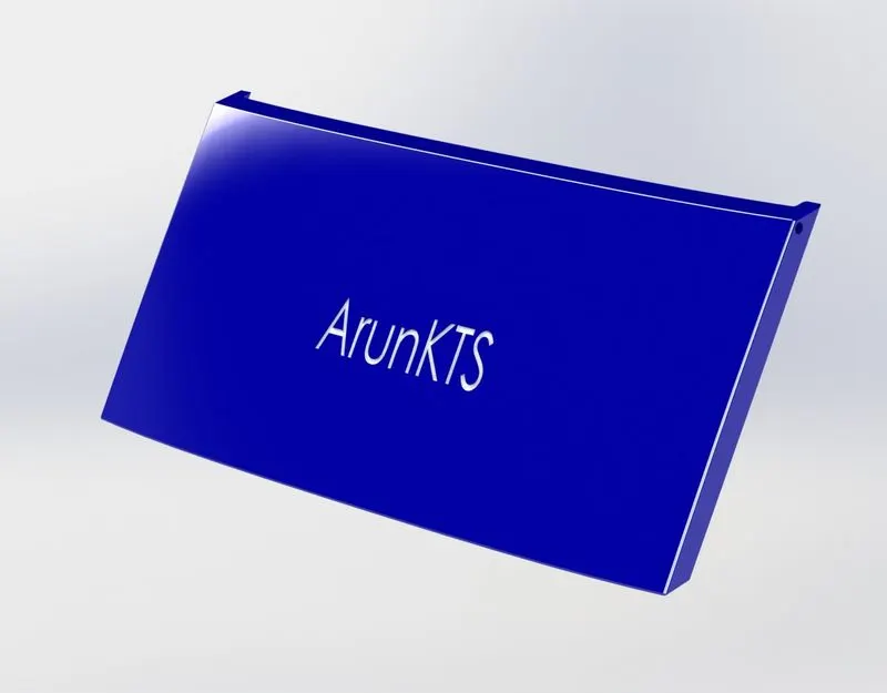
The commands used to model the Garage Door is:
- Extruded Cut
- Shell
- Mirror
- Fillet
The following are the procedure to model the garage door:
- The solid-body split while modeling hull part was imported model the garage door by using extruded cut with required dimensions.
- At the inner face of the garage door, a shell feature was used and sharp edges were removed using fillets.
- The garage door holder was created using extruded cut.
- Then the other half of the garage door mirrored and make sure the necessary fillets were applied before mirroring.
- Text on the outer surface of the garage carved using extruded cut.
- Finally, the desired appearances were applied.
9. Propeller
A propeller is a rotating fan-like structure that is used to propel the ship by using the power generated and transmitted by the main engine of the ship.
The transmitted power is converted from rotational motion to generate a thrust which imparts momentum to the water, resulting in a force that acts on the ship and pushes it forward.
A ship propels on the basis of Bernoulli’s principle and Newton’s third law. A pressure difference is created on the forward and aft side of the blade and water is accelerated behind the blades.
The thrust from the propeller is transmitted to move the ship through a transmission system which consists of a rotational motion generated by the main engine crankshaft, intermediate shaft and its bearings, stern tube shaft and its bearing and finally by the propeller itself.
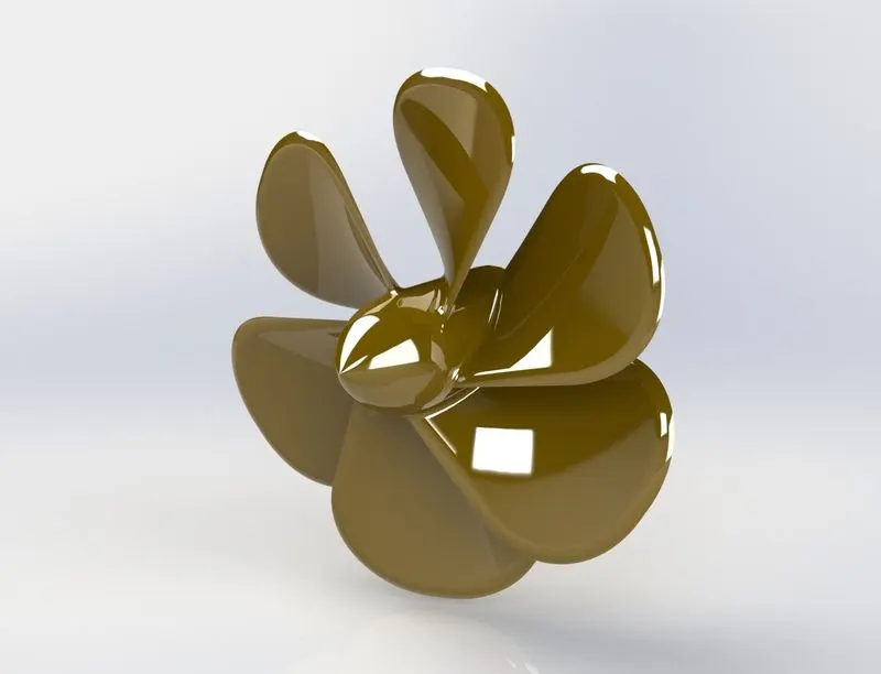
The commands used to model the Propeller is:
- Revolved Boss/Base
- Lofted Boss/Base
- Circular pattern
- Reference Plane
- Extruded Cut
- Fillet
The following are the procedure to model the propeller:
- The boss of the propeller was created by using revolved boss/base.
- The blade of the propeller was created using lofted boss/base, reference plane and fillets.
- Then blades were modeled around the boss using a circular pattern
- A hole in the boss is created using extruded cut and then necessary fillets were applied.
- Finally, the part was saved by applying desired appearances.
Assembly:
We can build complex assemblies consisting of many components, which can be parts or other assemblies, called subassemblies. For most operations, the behavior of components is the same for both types. Adding a component to an assembly creates a link between the assembly and the component. When SOLIDWORKS opens the assembly, it finds the component file to show it in the assembly. Changes in the component are automatically reflected in the assembly.
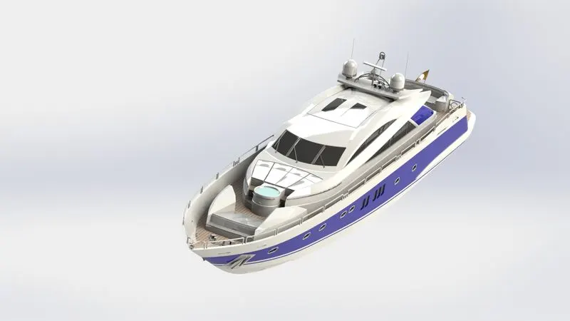
Commands used in Assembly:
The following commands are used in assembling parts of a yacht in the Solidworks Assembly.
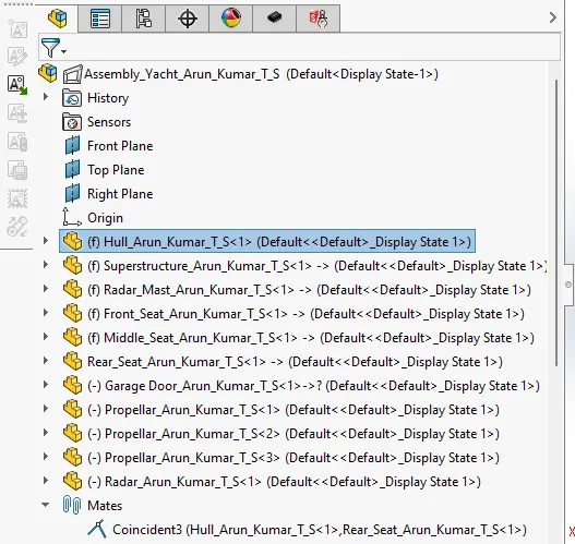
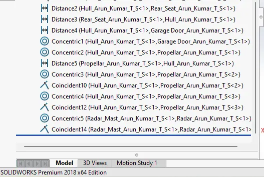
- Mates: Mates create geometric relationships between the components. It defines the allowable directions of linear and rotational movement of the components. The mates have several other options like
- Coincident mates: which makes two planar faces become coplanar.
- Concentric mates: This mate forces two cylindrical faces to become concentric.
- Distance Mate: This mate allows you to make a specified distance between two parts.
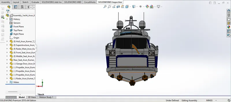
Firstly, Hull was imported manually in the assembly and hull’s front plane, midplane and top plane were coincident with assembly window’s planes. Then all the parts are imported one by one by applying the required mates.
Rendering:
Rendering is the process of creating a photo-realistic image in a real-life environment. The render is done in PhotoView 360 of the Solidworks. The realistic render is created in Solidworks visualize.
Appearances: An appearance defines the visual properties of a model, including colour and texture. Appearances do not affect physical properties, which are defined by materials.
Decals: A decal is a 2D image applied to a model. It can be used to apply warning or instruction labels to models. It is to create model details that you can represent with an image instead of with the model geometry, such as a car grill or a picture frame.
Lights: Adjust the direction, intensity, and colour of light in the shaded view of a model. We can add light sources of various types, and modify their characteristics to illuminate the model as needed. We can change the appearance of the model to enhance or reduce the effect of lighting properties.
Camera: By adding cameras to model documents and view the model from the camera perspective.
- Specify the positions of targets and cameras.
- Attach cameras to objects and sketch entities. The camera can then show motion or move with the entity.
- Place cameras inside models.
- Roll cameras to specified angles.
- Control properties of a field of view and depth of field.
- Use cameras in animations.
Environment: We can change the background with HDR environments so that it will give the assembled model a real-life-like appearance.
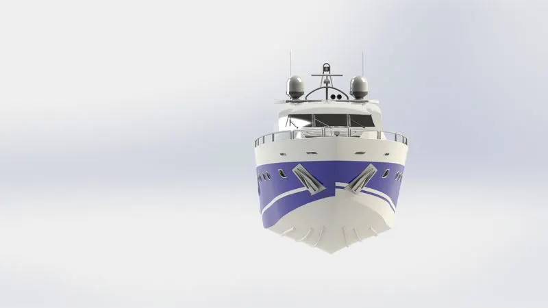
Conclusion:
In this project, we have understood surface modeling, where we explored different kinds of surface commands to model any 3D object. Solidworks surfacing tool allows you to model complex design geometries in an easy and efficient manner.
Here we used a surfacing tool majorly to design most of the parts of the American Predator Yacht, then we assembled every part of it by applying desired appearances and decals. After this, we have rendered the model in the Solidworks Photoview 360 with proper setup of lights, cameras, and scenes. Finally, we have rendered the model in the Solidworks visualize for more detailed renders with the real-life environment.