Modeling, Assembly, and Rendering of Sunseeker Predator Yacht
Objectives: Following were the objectives of this project.
- Learn SolidWorks.
- Modeling with the help of Sunseeker Predator Yacht Blueprints.
- 3D Modeling and appearance of different parts with the help of SolidWorks software.
- Assemble different parts under SolidWorks Assembly with the help of different mates.
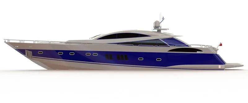
- Photo realistic rendering with the help of photo view 360.
Introduction: SolidWorks is a parametric modeling software released by Dassault Systèmes in the year of 1997. It is widely used to design products both for the automotive and manufacturing sector. It is also used to perform FEA Analysis, PCB Design, and Computation Fluid Dynamics (CFD). It can also advise users on real-world weight, density, and other mechanical properties when modeling or creating parts. It is also had an added feature called Photo view 360, which can be used to perform Rendering for different designs.
Design Methodology: Following design approach was followed:
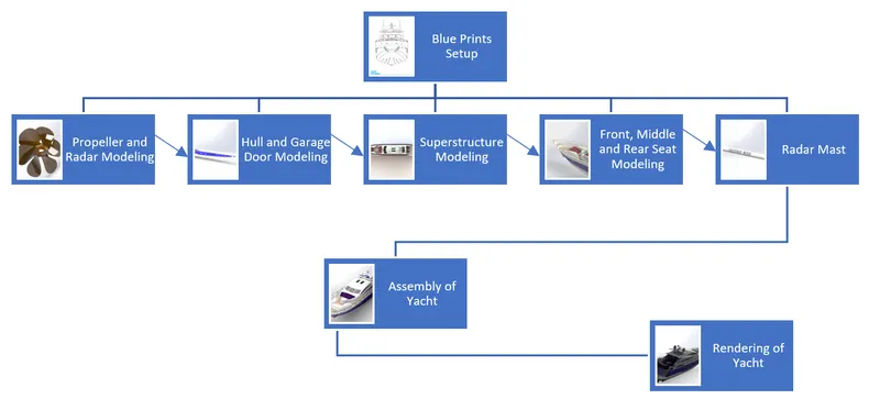
Following features are used to model all parts of Predator Yacht:
- Blueprint Setup- It is the process where need to set up blueprints for reverse engineering for all components and for the final model.
- Sketch Creation- This is the first process to draw a profile. This profile was used later to create different solid and surface features.
- Extruded Boss- This is used to create a solid body with the help of 2D sketches.
- Extruded Cut- It is used to remove material from the 3D model with help of a 2D profile.
- Fillet and Chamfer- The fillet command is used to create rounded internal and external edges.While the Chamfer is used to break sharp edges with a bevel.
- Lofted Boss- This feature is used to add materials between two or more profiles with the help of guide curves.
- Pattern (Circular, Linear)- It is used to make liner patterns of previously made features and faces.
- Knit Surface- This feature is used to join two or more two surfaces and converted them into a single entity.
- Trim Surface- This feature can remove unnecessary surfaces.
- Extend Surface- This feature can extend the surface using edges.
- Fill Surface- This feature can create a surface in the close boundary.
- Surface Extrude- This feature covert any 2D sketch into extruded to create a surface.
- Revolved Boss/Bass- First, need to select the above sketch and construction line (Dotted) as an axis of revolution.
- Mirror- This feature is used to copy features across planes or Lines.
- Curvedriven Pattern- This feature is used to create patterns along a plane or 3D curve.
- Dome- It can be used to apply a dome on faces where the center is located outside the face.
- Draft- This feature is used to provide taper on specified angles, using a neutral plane or parting line.
- Shell- This feature is used to create a spherical shape or Dome on 3D parts or shapes.
- Split- This feature is used to cut the part across some sketch boundary and to remove that part from the main model.
- Reference Geometry- This feature is used to create plans, axes, coordinate systems, and points.
- Curves- This feature is used to create one 3D curve from two 2D curves drawn on different plans.
- Combine- This feature is used to join two or more solid bodies into a single entity.
Following Components were modeled:
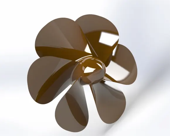
- Propeller- Sketch, Revolve, Loft, Fillets, Cut Extrude, and Circular Pattern commands used to create Propeller.
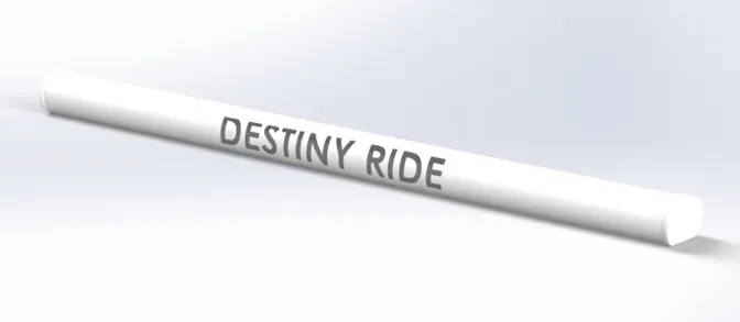
- Radar- Sketch, Extruded Boss, Fillets, Extruded Cut, Pattern, Mirror, and Split Line, used to create Radar.
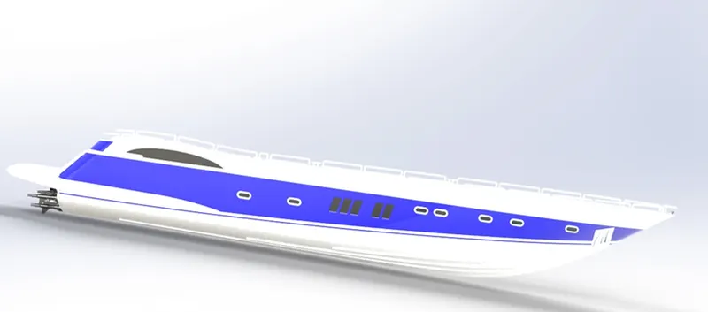
- Hull- Sketch, Projected Curve, Surface Loft, Surface Trim, Surface Extend, Surface Trim, Surface Fill, Surface Knit, Shell, Extruded Boss, Chamfer, Fillet, Sweep, Dome, Helix/Spiral, and Mirror features are used to create Hull.
- Garage Door-Extruded Cut, Shell, Fillet, and Mirror features are used to create Garage Door.
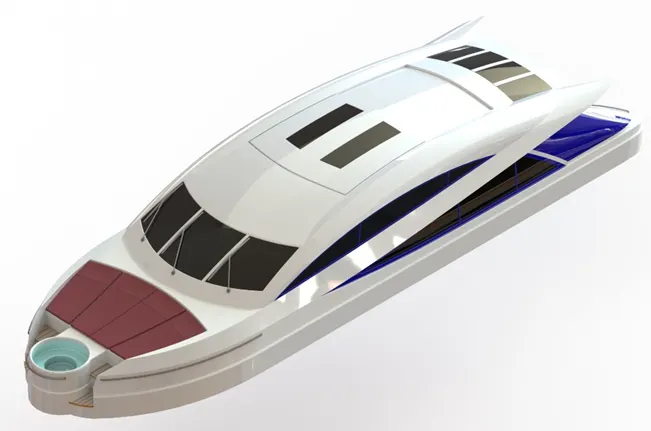
- Superstructure- Sketch, Surface Extrude, Surface Sweep, Surface Knit, Fillet, Projected Curve, Surface Loft, Surface Fill, Surface Trim, Surface Knit, and Ruled Surface features are used to create Superstructure.
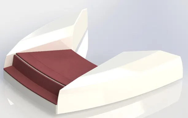
- Front Seat- Sketch, Surface Sweep, Surface Extrude, Surface Trim, Surface Loft, Surface Fill, Surface Knit, Chamfer, Fillet, Dome, Mirror, and Extruded Cut, features are used to create Front Seat.
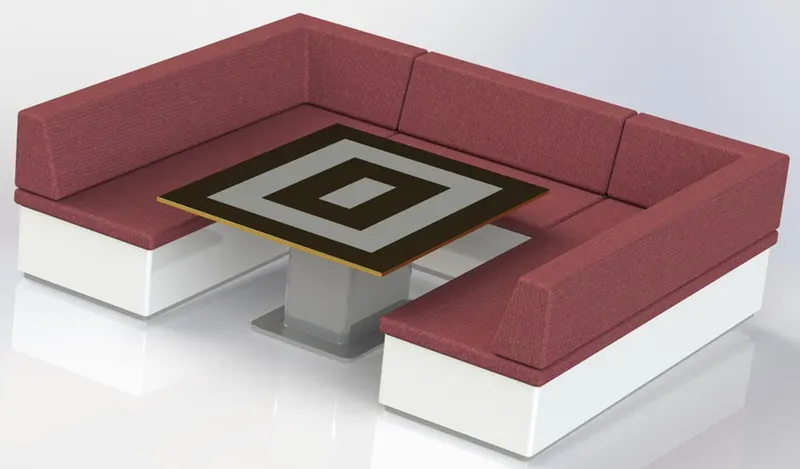
- Middle Seat- Sketch, Extruded Boss, Chamfer, Fillet, Mirror, and Extruded Cut, features are used to create Middle Seat.
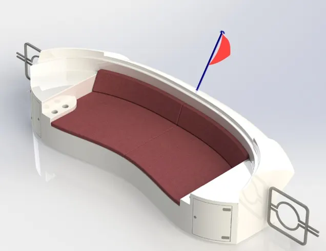
- Rear Seat- Sketch, Surface Sweep, Surface Offset, Surface Knit, Surface Trim and Surface Loft, features are used to create Rear Seat.
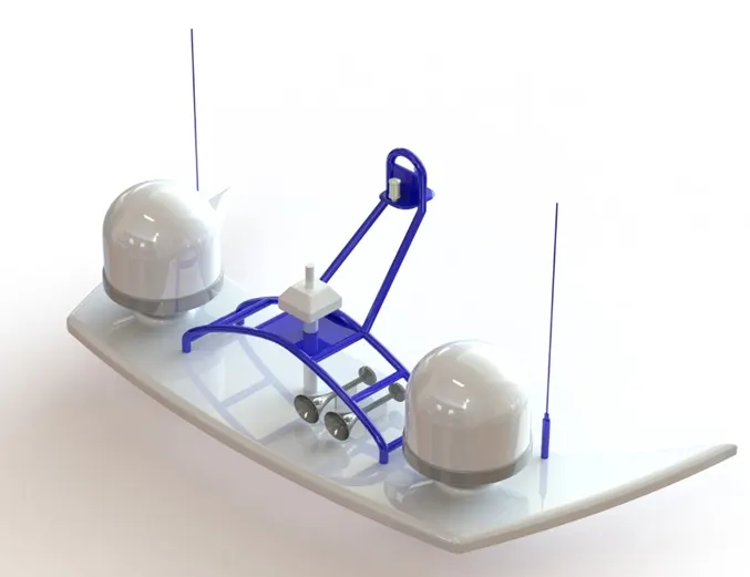
- Radar Mast- Sketch, Extruded Boss, Fillet, Revolve, Sweep, Shell, and Mirror, features are used to create Radar Mast.
Final Assembly of Predator Yacht:
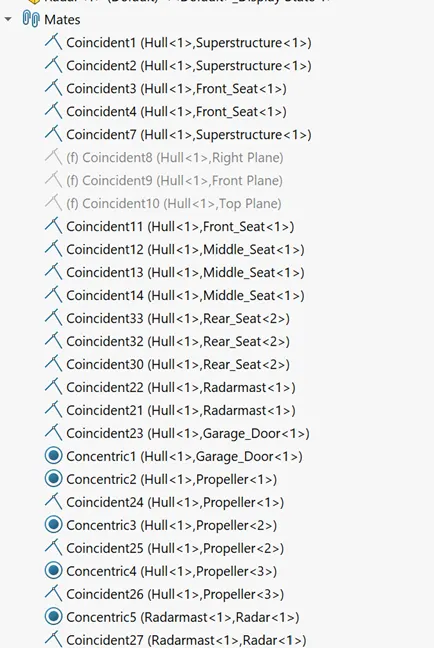
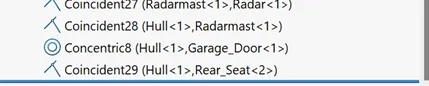
- Mates Used- Following Mates are used to model the final Assembly.
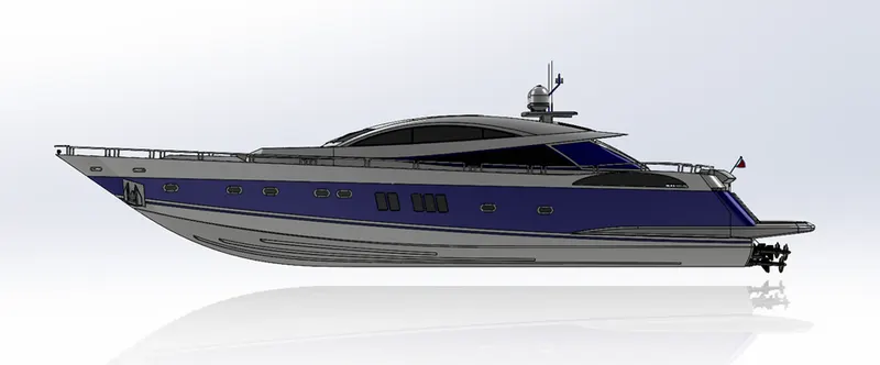
- Front View-
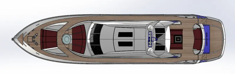
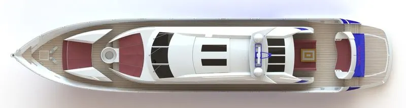
- Top View-
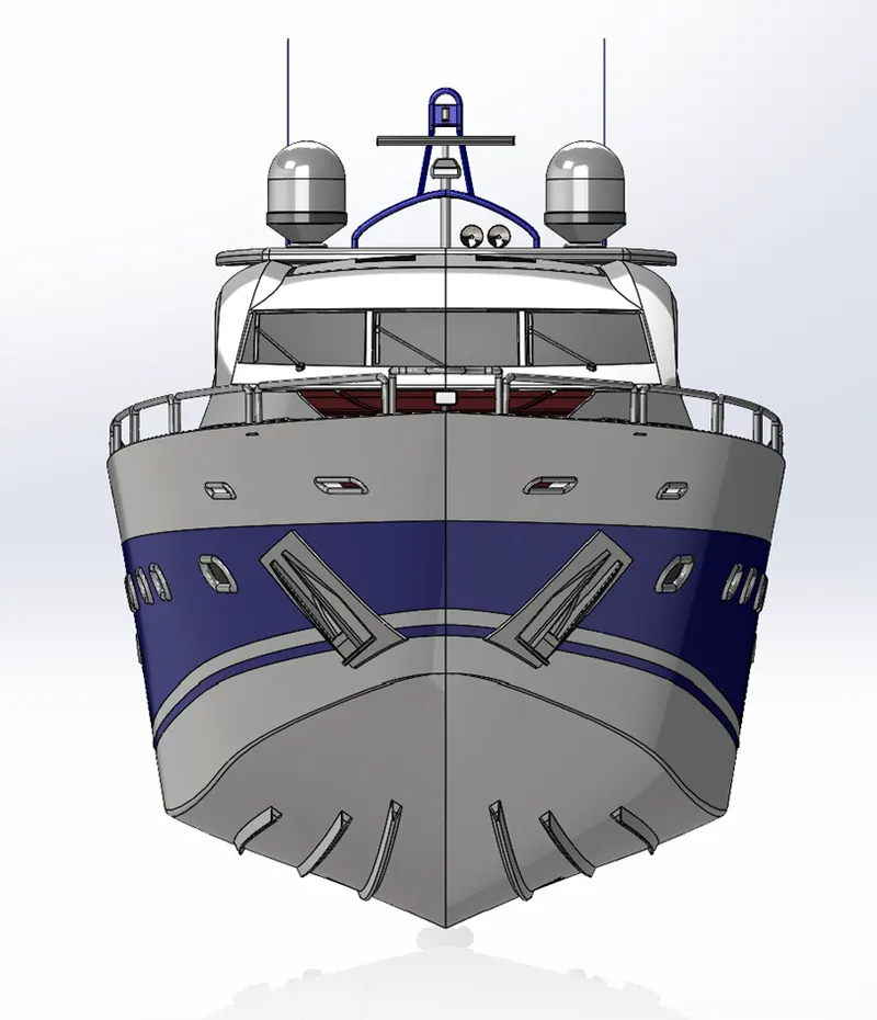
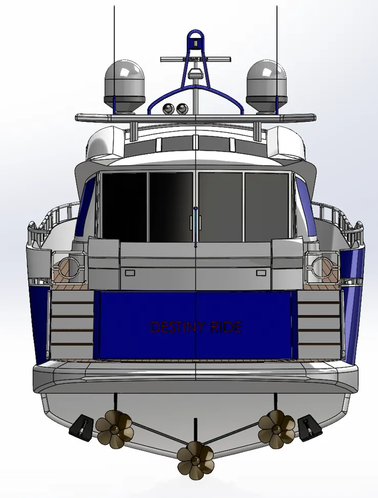
- Side View-
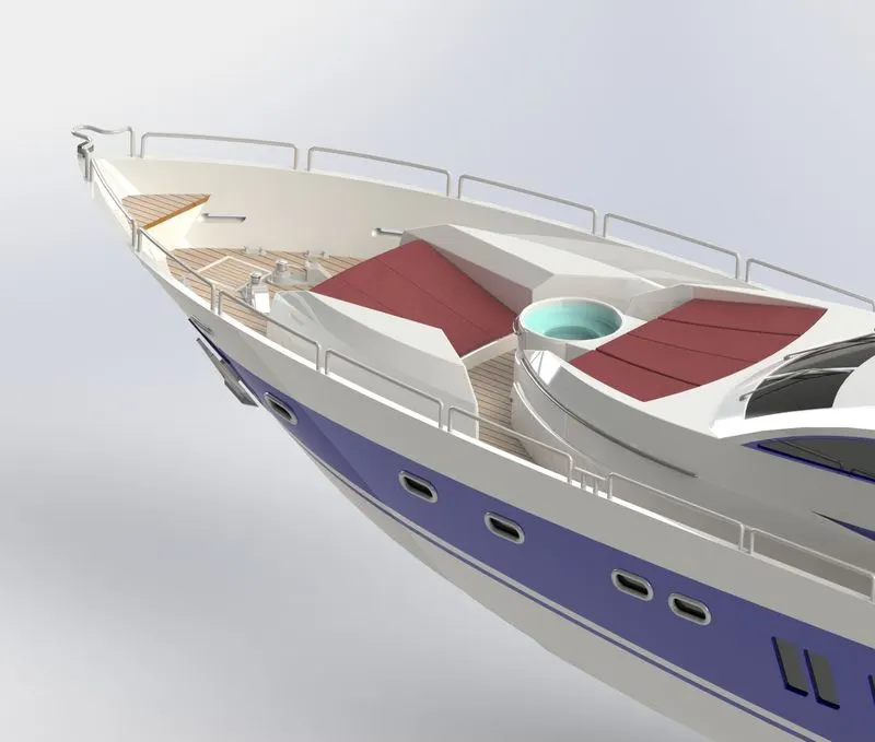
- ISO View-
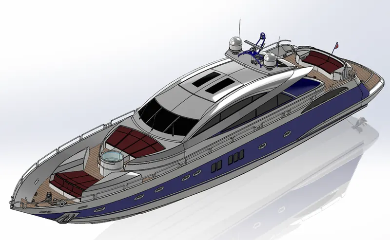
Final Rendering:
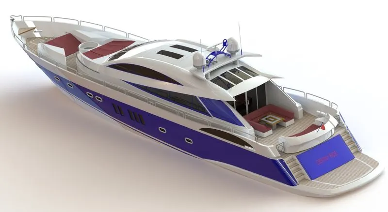
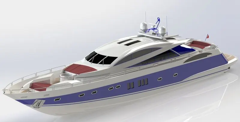
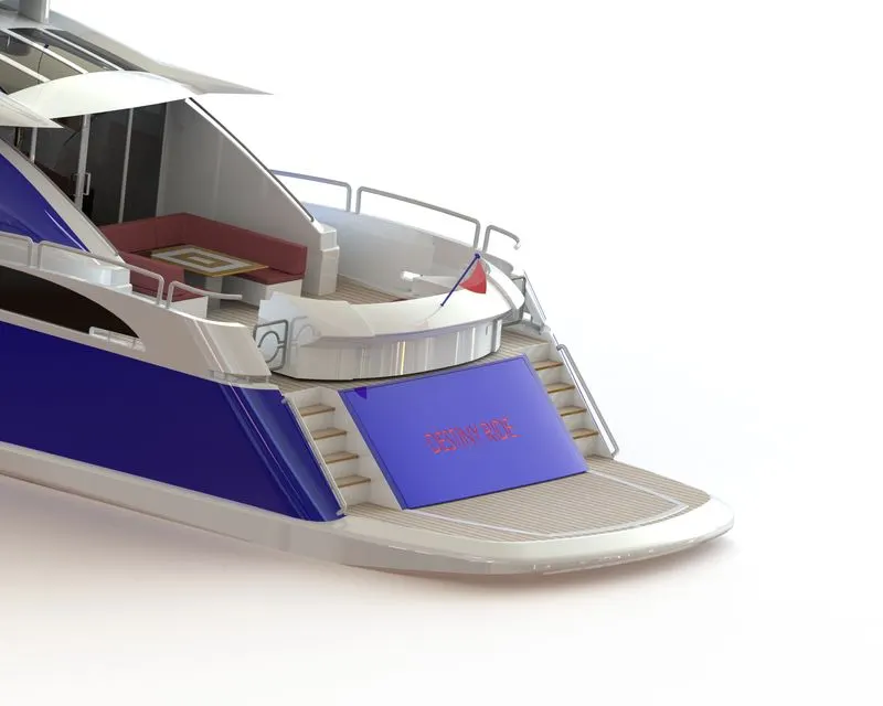
Rendering is a design process used to create realistic images of the created model. Photoview 360 and SolidWorks Visualize are the best way to render any model created using SolidWorks. Photoview 360 is the inbuilt tool into Solidworks. While SolidWorks Visualize is a separate software that can render more realistic images. Below is the Sunseeker Predator Yacht under SolidWorks Photoview 360.
Photoview 360-
Conclusion:
It is concluded that all components are designed successfully as well assembled with the best possible mates. It is successfully rendered under Photoview 360.