Modeling, Assembly, and Rendering of Boeing 747-8 Using SolidWorks.
Objectives: Following were the objectives of this project.
- Learn SolidWorks.
- Modeling with the help of Boeing 747-8 Blueprints.
- 3D Modeling and appearance of different parts with the help of SolidWorks software.
- Assemble different parts under SolidWorks Assembly with the help of different mates.
- Photo realistic rendering with the help of photo view 360.
Introduction: SolidWorks is a parametric modeling software released by Dassault Systèmes in the year of 1997. It is widely used to design products both for the automotive and manufacturing sector. It is also used to perform FEA Analysis, PCB Design, and Computation Fluid Dynamics (CFD). It can also advise users on real-world weight, density, and other mechanical properties when modeling or creating parts. It also had an added feature called Photo view 360, which can be used to perform Rendering for different designs.
Design Methodology: The following design, approach was followed:
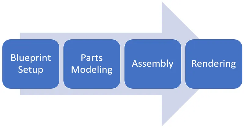
In Order to design the whole Boeing 747-8; the following parts and their subparts were modeled.
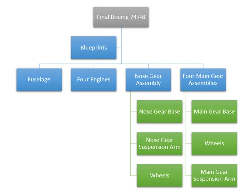
Descriptions: Following features are used to model all parts of Boeing 747-8:
- Blueprint Setup- It is the process where need to set up blueprints for reverse engineering for all components and for the final model.
- Sketch Creation- This is the first process to draw a profile. This profile was used later to create different solid and surface features.
- Extruded Boss- This is used to create a solid body with the help of 2D sketches.
- Extruded Cut- It is used to remove material from the 3D model with help of a 2D profile.
- Fillet and Chamfer- The fillet command is used to create rounded internal and external edges.While the Chamfer is used to break sharp edges with a bevel.
- Lofted Boss- This feature is used to add materials between two or more profiles with the help of guide curves.
- Pattern (Circular, Linear)- It is used to make liner patterns of previously made features and faces.
- Knit Surface- This feature is used to join two or more two surfaces and converted them into a single entity.
- Trim Surface- This feature can remove unnecessary surfaces.
- Extend Surface- This feature can extend the surface using edges.
- Fill Surface- This feature can create a surface in the close boundary.
- Surface Extrude- This feature covert any 2D sketch into extruded to create a surface.
- Revolved Boss/Bass- First, need to select the above sketch and construction line (Dotted) as an axis of revolution.
- Mirror- This feature is used to copy features across planes or Lines.
- Curvedriven Pattern- This feature is used to create patterns along a plane or 3D curve.
- Dome- It can be used to apply a dome on faces where the center is located outside the face.
- Draft- This feature is used to provide taper on specified angles, using a neutral plane or parting line.
- Shell- This feature is used to create a spherical shape or Dome on 3D parts or shapes.
- Split- This feature is used to cut the part across some sketch boundary and to remove that part from the main model.
- Reference Geometry- This feature is used to create plans, axes, coordinate systems, and points.
- Curves- This feature is used to create one 3D curve from two 2D curves drawn on different plans.
- Combine- This feature is used to join two or more solid bodies into a single entity.
Blueprints setup: It is necessary to set up blueprints to do reverse engineering.
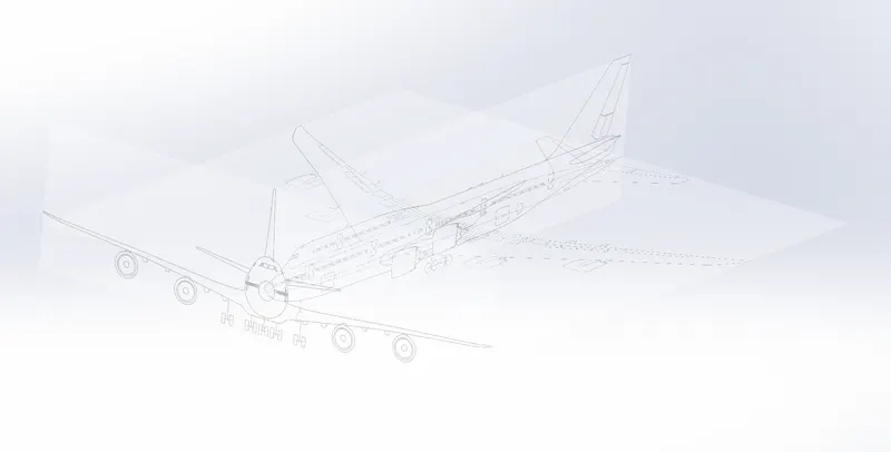
The following Parts were modeled to create a full assembly of Boeing 747-8:
Main Body: This consists of the following subparts.
Fuselage- It is the main body that holds all the people and cargo. It is approximately 24 meters which makes it the world's largest airplane. The following tools and features are used to model it.
- Sketch
- Line
- Spline
- Smart Dimension
- Convert Entities
- Fillet
- Projected Curve
- Lofted Surface
- Mirror
- Thicken
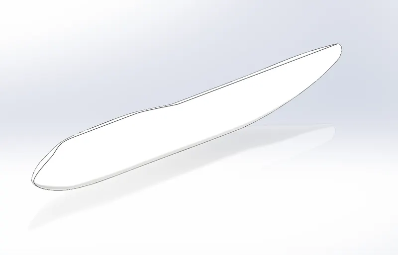
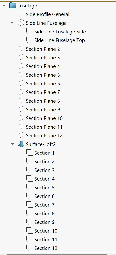
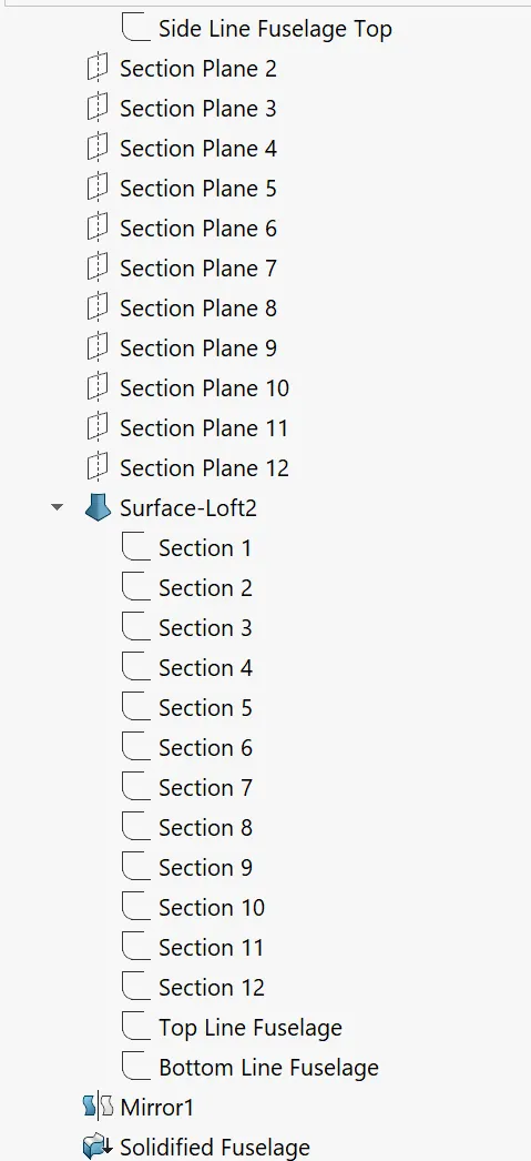
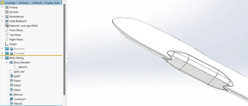
Belly Fairing- It is necessary to reduce drag and can carry extra cargo and fuel. It is located underside of the fuselage between the main wings. The following features are used to model belly fairing.
- Sketch
- Extruded Base/Boss
- Fillet
- Split
- Combine
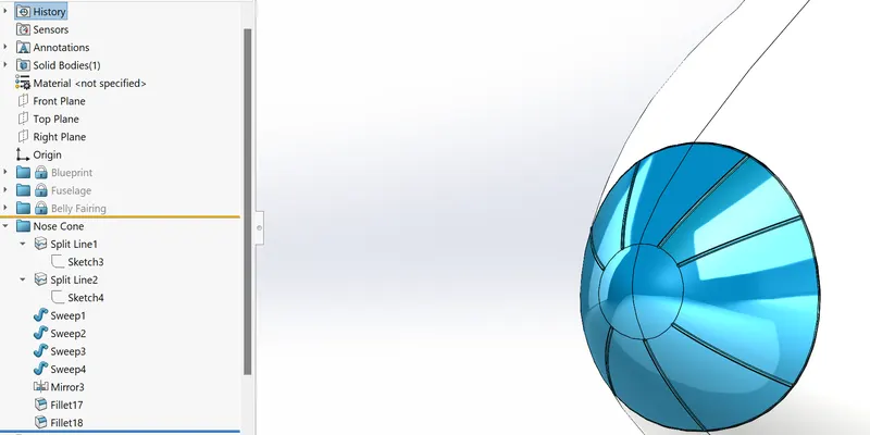
Nose Cone- It is designed to modulate oncoming airflow behaviors, minimize aerodynamic drag, and protect radar from the aerodynamic force that is generated by weather. The following features are used to model Nose Cone.
- Sketch
- Split Line
- Circle
- Trim
- Swept Boss/Base
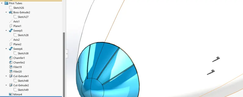
Pitot Tubes- These are flow measurement instruments to measure the speed of aircraft. The following features are used to model pitot tubes.
- Sketch
- Boss Extruded
- Sweep
- Fillets
- Chamfer
- Extruded Cut
- Mirror
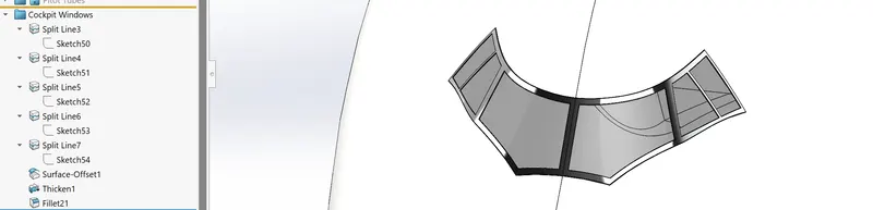
Cockpit Windows- These are the transparent sections, which allow the pilots to navigate the aircraft. They are made from anti-reflective coating glass and equipped with a heater to melt ice. The following features are used to model Cockpit Windows.
- Sketch
- Split Line
- Surface Offset
- Thicken
- Fillet
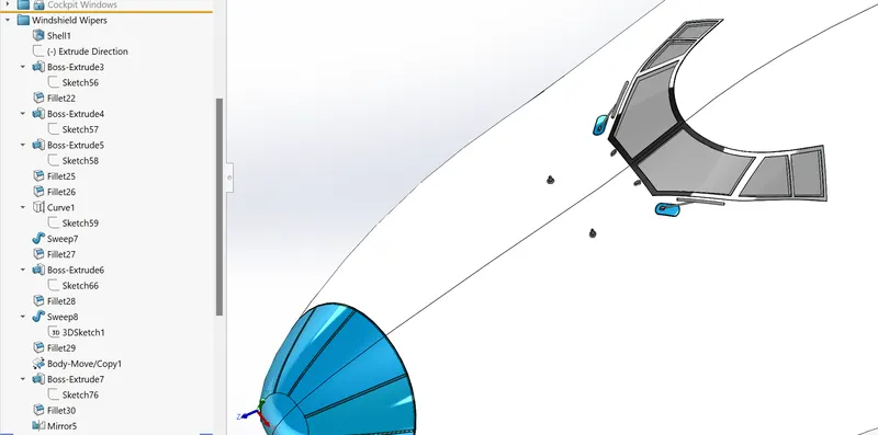
Windshield Wipers- These are devices to remove water, snow, ice, and debris from the windshield. A wiper usually is a metal arm, which pivots about one end and is fitted with a rubber blade on the other end. The following features are used to model Windshield Wipers.
- Sketch
- Shell
- Boss Extrude
- Fillet
- Curve
- Sweep
- Body Move/copy
- Mirror
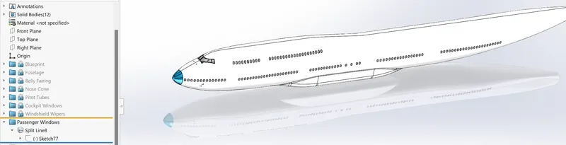
Passenger Windows- These are enclosed openings in the fuselage that allow people to view the outside environment. The following features are used to model passenger windows.
- Sketch
- Block
- Insert Block
- Linear Sketch Pattern
Doors and Hatches- The following features are used to model Doors and Hatches.
- Sketch
- Block
- Insert Block
- Linear Sketch Pattern
- Fillet
- Split Lines
- Surface Offsets
- Thicken
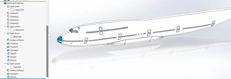
Lights and Antennas- These are located on the body of the aircraft and its wings for air traffic communication as well as identification. The following features are used to model Lights and Antennas.
- Sketch
- Revolved Boss/Base
- Fillet
- Split
- Linear Patterns
- Boss Extrude
- Body Move/copy
- Split Line
- Surface Offset
- Draft
- Dome
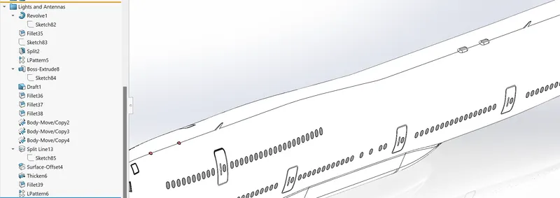
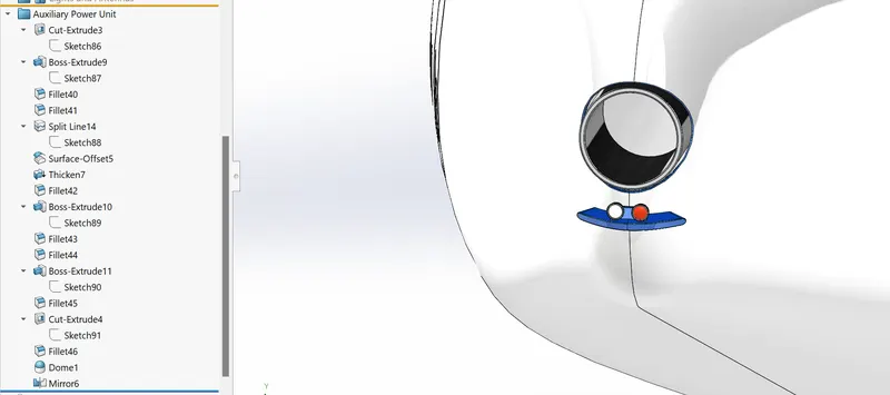
Auxiliary Power Unit- It consists of the exhaust and tail lights at the rear end of the aircraft body. The following features are used to model Auxiliary Power Unit.
- Sketch
- Cut Extrude
- Boss Extrude
- Fillet
- Split Line
- Surface Offset
- Thicken
- Dome
- Mirror
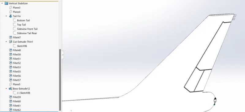
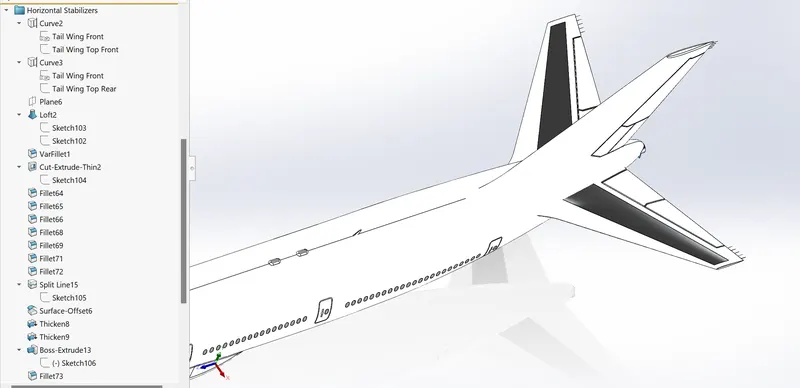
Vertical and Horizontal Stabilizers- It provides stability to the aircraft during flight in both vertical and horizontal planes. The following features are used to model Vertical and Horizontal stabilizers.
- Sketch
- Lofted Surface
- Fillet
- Cut Extrude Thin
- Boss Etude
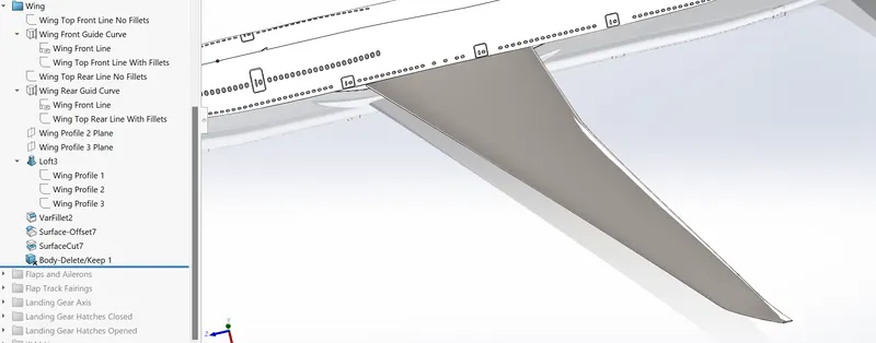
Wing- It is a fin-like structure that provides the lift for an airplane to move along with air. Its design totally based on Aerodynamics requirements. The following features are used to model Wing.
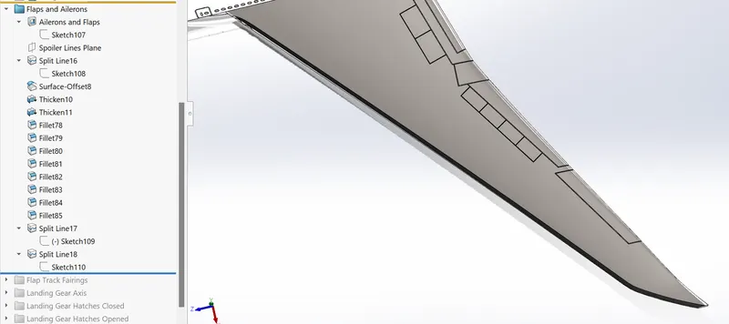
Flaps and Ailerons- These control the motion of the aircraft along a different axis. The following features are used for Flaps and Ailerons.
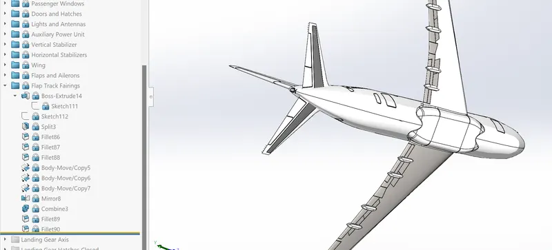
Flap Track Fairing- The following features are used for Flap Track Fairing.
Land Gear Axis-
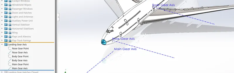
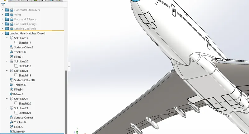
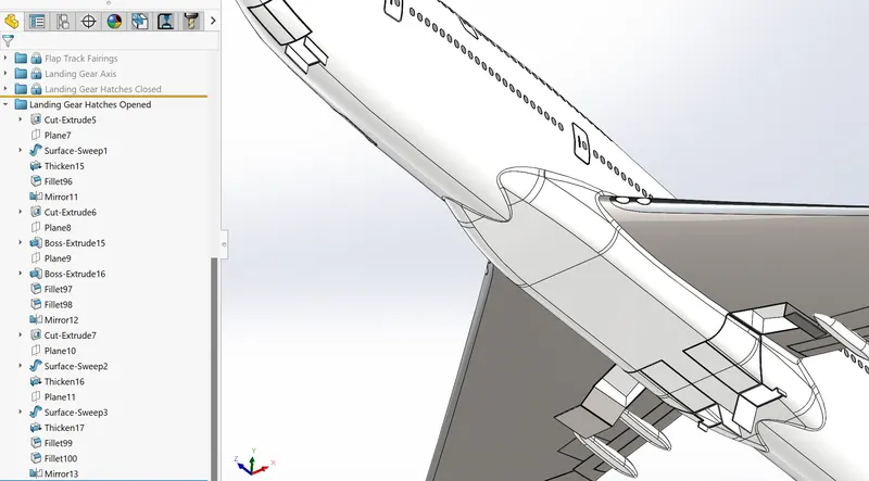
Landing Gear Hatches (Closed and Open)- These are openings that allow the landing gears to retract after take-off and expand before landing. The following features are used for Landing Gear Hatches (Closed and Open).
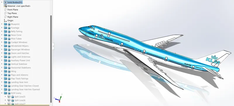
KLM Livery-
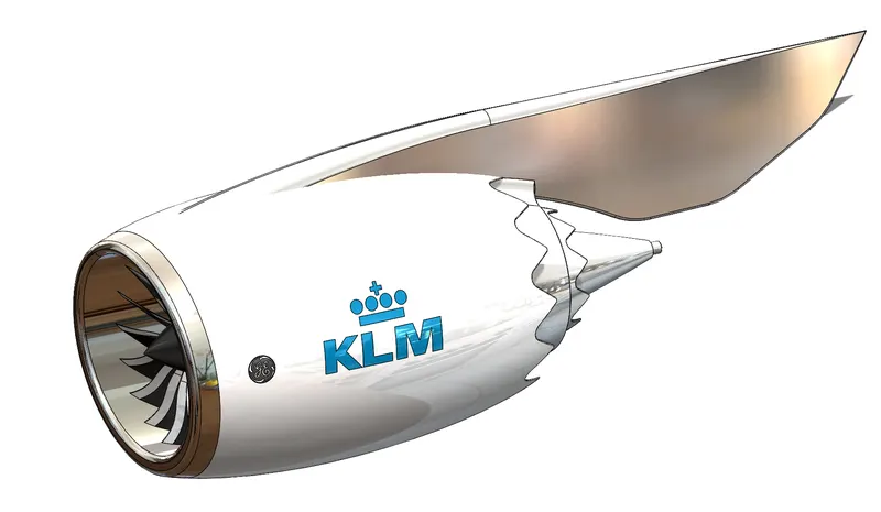
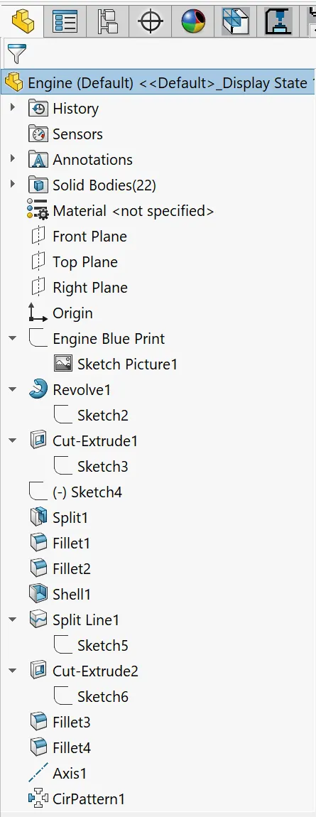
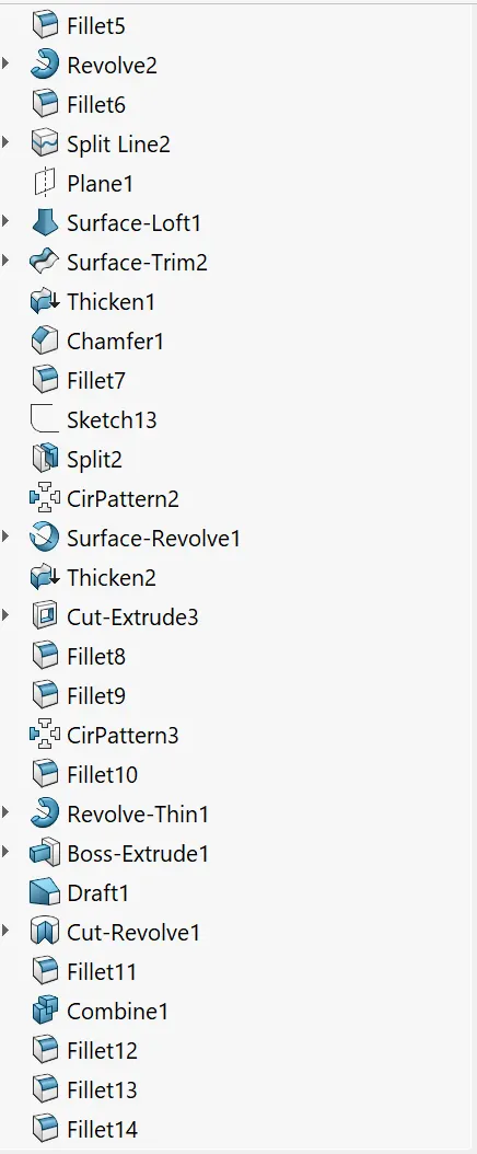
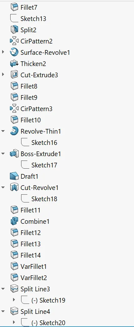
Engine: The Boeing 747-8 has four General Electric turbofan jet engines, two located on each wing. The following features are used for the Engine.
- Sketch
- Blueprints
- Line
- Spline
- Centerline
- Smart Dimension
- Revolved Boss/Base
- Circle
- Extruded Cut
- Split
- Fillet
- Shell
- Split Line
- Reference Geometry
- Circular Pattern
- Lofted Surface
- Trim Surface
- Thicken
- Chamfer
- Revolved Surface
- Convert Entities
- Offset Entities
- Extruded Boss/Base
- Draft
- Revolved Cut
- Combine
- Variable fillet
- Add Appearance
- Edit Appearance
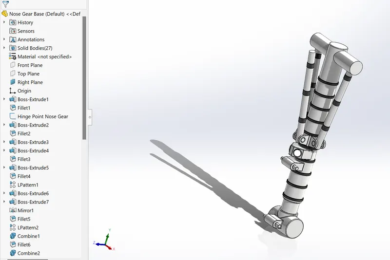
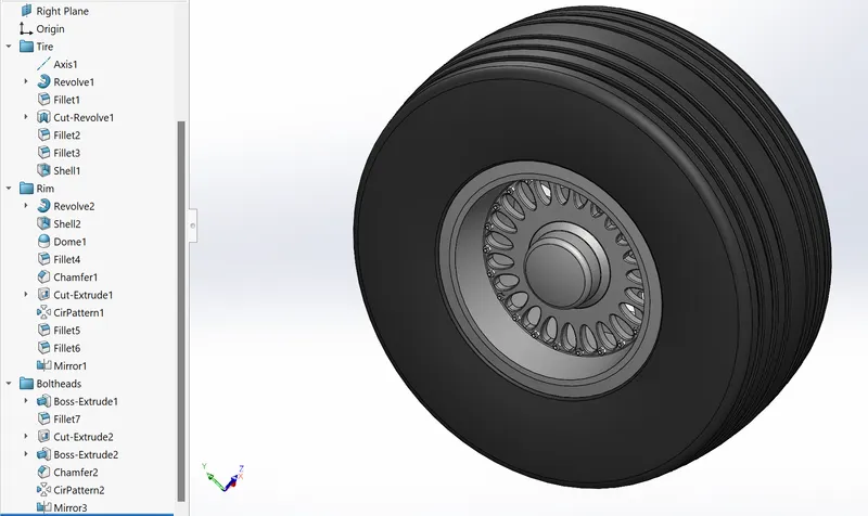
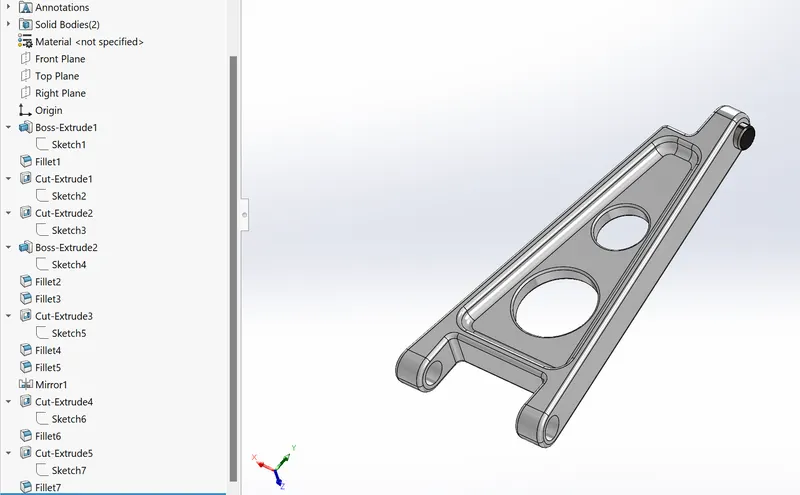
Nose Gear Assembly: It is the assembly of the following components.
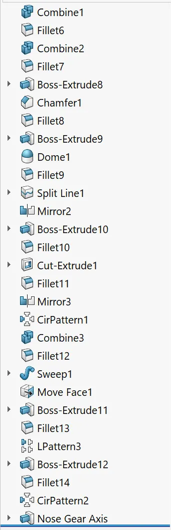
- Nose Gear Base-
- Wheels-
- Nose Gear Suspension Arms-
Final Assembly of Nose Gear:
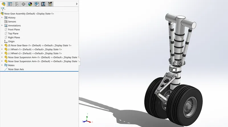
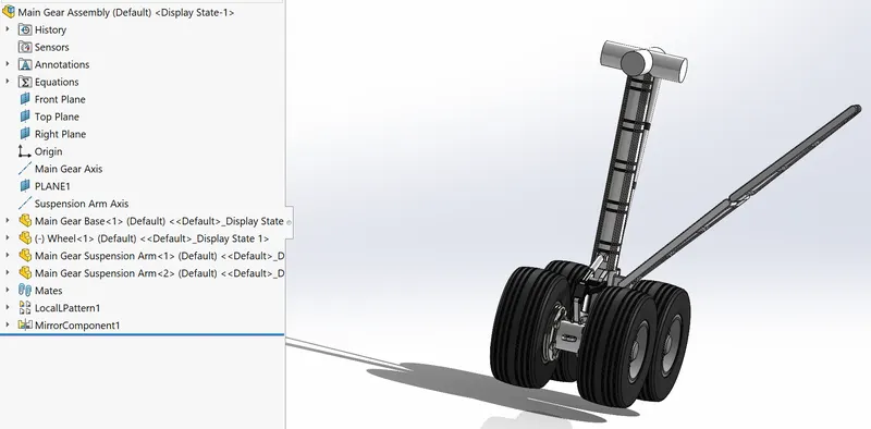
Main Gear Assembly: It is the assembly of the following components.
- Main Gear Base-
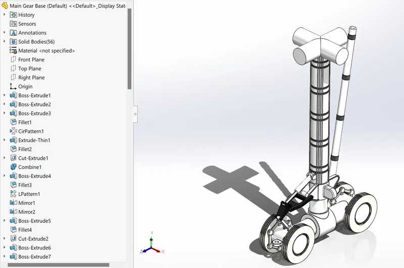
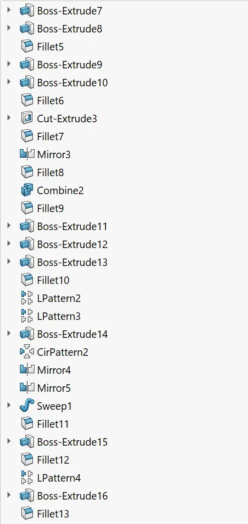
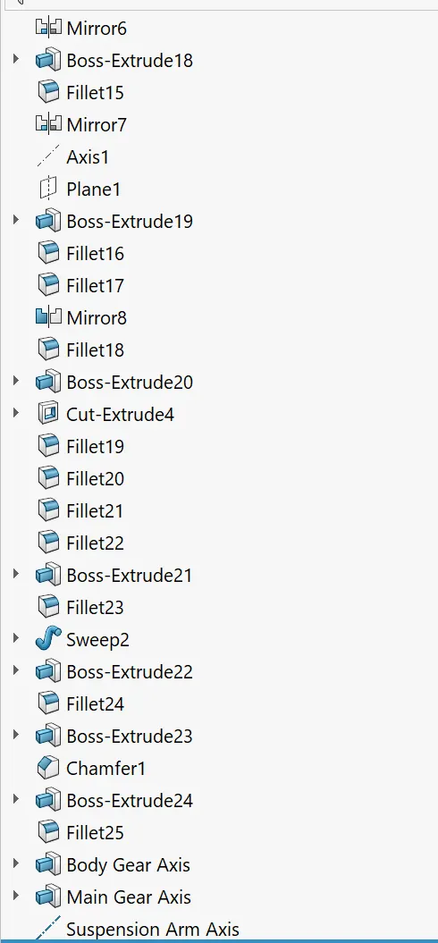
- Wheels-
-
- Main Gear Suspension Arms-
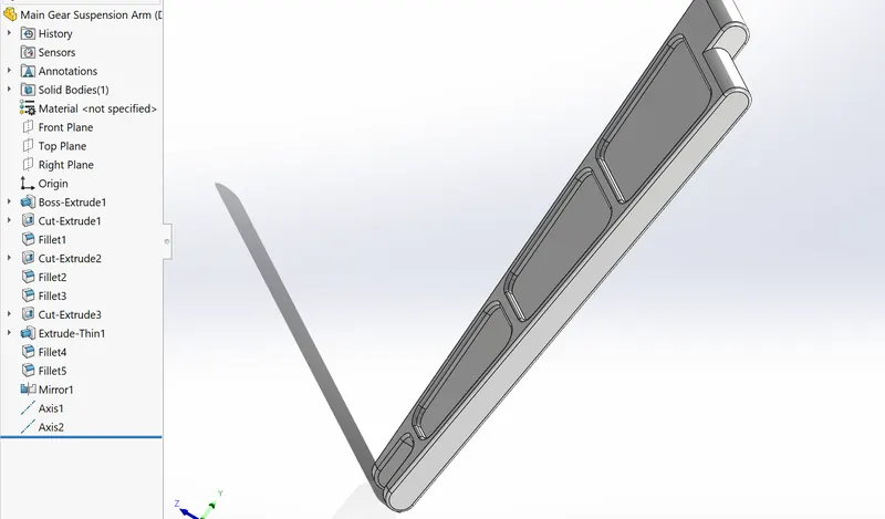
Final Assembly of Main Gear:
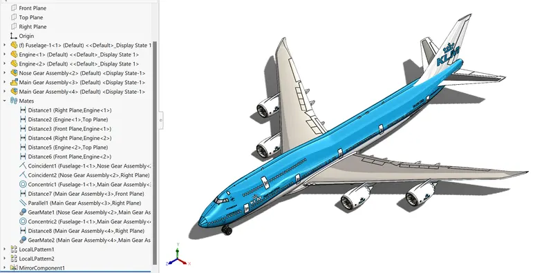
Final Assembly of Boeing 747-8:
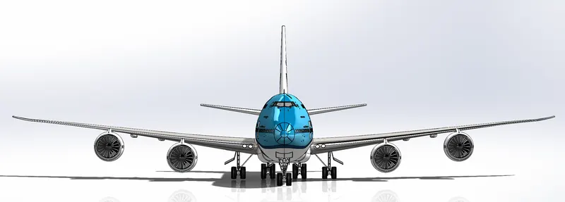
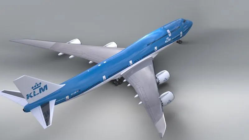
Final Rendering:
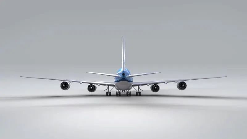
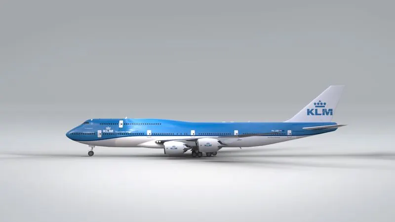
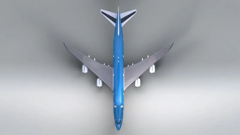
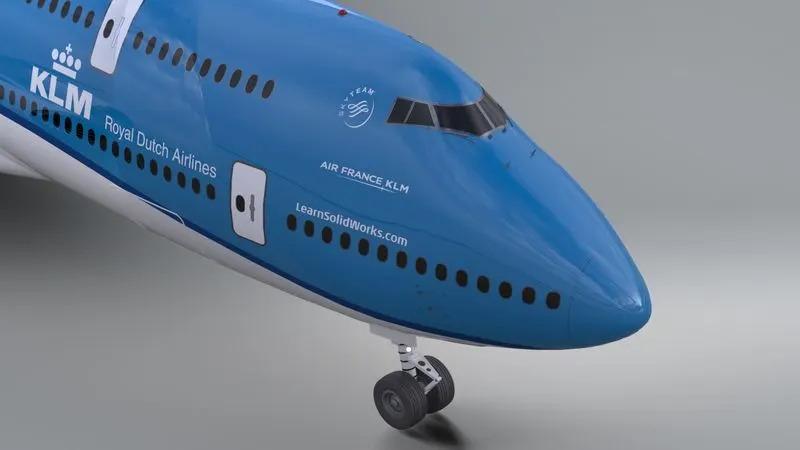
Rendering is a design process used to create realistic images of the created model. Photoview 360 and SolidWorks Visualize are the best way to render any model created using SolidWorks. Photoview 360 is the inbuilt tool into Solidworks. While SolidWorks Visualize is a separate software that can render more realistic images. Below is the Boeing 747-8 under SolidWorks Photoview 360 and SolidWorks Visualize.
Photoview 360-
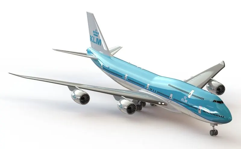
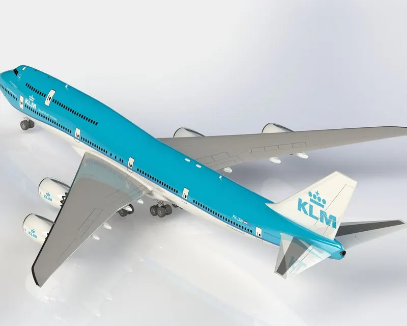
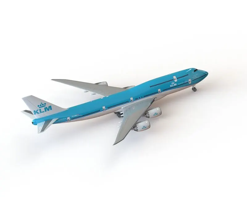
SolidWorks Visualize-
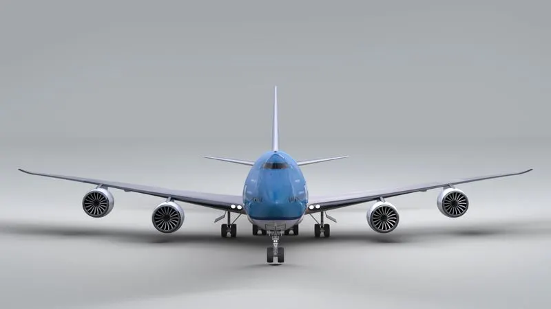
Conclusion:
It is concluded that all components are designed successfully as well assembled with the best possible mates. It is successfully rendered under Photoview 360 and SolidWorks Visualize.