Radar Mast & Final Assembly of Yacht
DESIGN OF SUNSEEKER PREDATOR YATCH USING SOLIDWORKS
OBJECTIVE
The main objective of this project is to design and model all the parts of Predator Yacht and assemble it to create the Photo-Realistic rendering of the yacht. The objective of the project is to design and model all the parts of a Sunseeker Predator Yacht and assembling it to create the Photo-Realistic rendering of the yacht. Then the modelled parts were assembled by adding proper math and constraints to create the Photo-Realistic rendered image of the Yacht. The SOLID WORKS is a mechanical design automation application that lets designers quickly sketch out ideas, experiment with features and dimensions, and produce models and detailed drawings.
INTRODUCTION
This project explains the designing of Sunseeker Predator Yatch using the CAD software SOLIDWORKS from sketching the parts and modelling them to final rendering of the assembly to give a photo realistic view.
METHODOLOGY
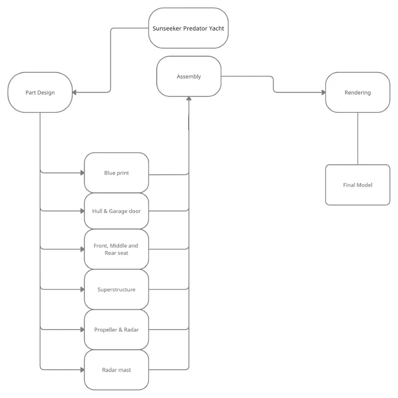
- Part Modelling
- Assembly
- Rendering
FLOW CHART
PART MODELLING
In part modelling, first the 2D sketch of the part is sketched using the tools in sketch tab and then the 2Dsketch is converted into a 3D part using features in the features tab.
FEATURES USED
Smart Dimensions: Smart dimensions are to change the dimensions of the sketch and helps to make the sketch fully defined
Sketch Picture: This command is used to insert the picture of the product in the sketch plane, this picture helps us as a reference element while creating a new model. scale tool is used to change the dimension of the picture in the sketch plane
Offset: offset is a command which is used for enlarging or shrinking the sketch geometry. instead of redrawing the sketch, offset command is used to copy the exiting sketch and pasting to a required offset distance.
Slots: In a sketch plane we can be able to produce four different types of slots which are able to support the sketches for drawing. The four different types of slots are straight slot, centre point straight slot, 3-point arc slot and centre point arc slot
Trim: Trim is a command which is used to remove the unwanted drawing in the sketch
Extend: This command is used to extend the sketch entities to the nearby entities
Mirror: With the help of mirror command, we can able to create a duplicate sketch
Sketch Pattern: The sketch pattern creates copies of existing drawing and places them wherever we need in the sketch
Linear Pattern: linear patterns to create multiple instances of one or more features that you can space uniformly along one or two linear paths
Circular Pattern: circular patterns to create multiple instances of one or more features that you can space uniformly around an axis
Extrude Boss / Base: This command is used to convert the drawn 2D sketch into the 3D model. By using the direction 1 and direction we can able to extrude the sketch in both the directions.
Revolve Boss / Base: Revolve boss/base is used to revolve the drawn sketch in a circular pattern and creates a solid body by taking the centre axis as a reference
Loft Boss/Base: Adds material between two or more profiles to create a solid feature
Boundary Boss/Base: Adds material between profiles in two directions to create a solid feature
Extrude Cut: It is used the cut the solid model by extruding the sketch profile in one or two directions
Hole Wizard: hole wizard is used to insert a hole on the selected surface of the solid body. By using this feature, we can create different types of holes and threads
Revolved Cut: This feature is used to cut the solid body by revolving the sketch profile around the axis
Swept Cut: It is used to cut the solid body by sweeping the closed profile along the open or closed path that has drawn
Fillet: Fillet command is used to remove the sharp edges on the solid body by creating a rounded internals or externals
Chamfer: Chamfer is also used to remove the sharp edges which reduces the possibility of cuts, and injuries, to people who is handling the metal piece.
Swept Surface: It is used to create a surface by sweeping a open or closed profile along the open or closed path.
Loft Surface: This command is used to create a surface between two or more profiles
Boundary Surface: This command is used to create a boundary surface between profiles in two directions
Knit Surface: Knit surface command is used to combine the two or more adjacent, non-intersecting surfaces together
Trim Surface: It is used to trim the surface where one surface intersects another surface, a plane, or a sketch
Extruded Surface: This command is used to extrude the surface from the sketch
Revolved Surface: creates a surface feature by revolving an open or closed profile around the axis
Filled Surface: constructs a surface patch within a boundary defined by existing model edges, sketches or curves
Offset Surface: creates offset surfaces by using one or more contiguous faces
Extend Surface: Extends the edge, multiple edges or the face on the surface, based on the end conditions and extension type
Ruled Surfaces: insert ruled surfaces from the edges
ASSEMBLY
Assembly is most often referred to putting components together in an assembly line, but more specifically, it refers to creating a complete product that performs an intended function. Changes in the component are automatically reflected in the assembly i.e. The rebuild option will automatically take place or else it will ask the user to rebuild the document.
ASSEMBLY APPROACHES IN SOLIDWORKS
- Top-Down Approach
- Bottom-Up Approach
RENDERING
Rendering or image synthesis is the automatic process of generating a photorealistic or non-photorealistic image from a 2D or 3D model using a computer program. The resulting image is referred to as the render.
MAJOR CATEGORIES IN RENDERING
- Real-Time Rendering
- Pre-Rendering
SOFTWARE USED
- Photo view 360
- Solidworks Visualize.
COMPONENTS DESIGNED
- Hull
- Super structure
- Radar
- Radar mast
- Propeller
- Garage door
- Front seat
- Rear seat
- Middle seat
DESCRIPTION
BLUE PRINT SETUP
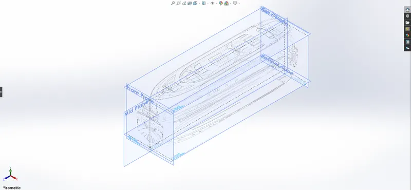
A blueprint can be a reproduction of a technical drawing or engineering drawing using a contact print process on light-sensitive sheets. blueprint can be used as a guide for making a design or pattern that can be followed. They were easier to read and faster to make due to the use of blue print. The above shown Blueprint was used to model the Yacht in a fully defined constraint. For setting up the Blueprint the Sketch pictures options were used and placed the different blueprints at the required planes.
HULL
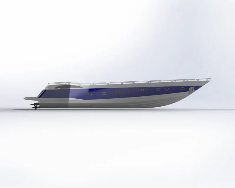
A hull is the watertight body of a ship or boat. The hull may open at the top (such as a dinghy), or it may he fully or partially covered with a deck. The line where the hull meets the water surface is caned the waterline. The hull of a ship is the most notable structural entity of the ship. To define the hull, it can be said that k is the watertight enclosure of the ship, which protects the cargo, machine, and accommodation spaces of the ship from the weather, flooding, and structural damage.
Features used
Convert entities
Mirror entities
Offset
trim
Surface sweep
Surface knit
Project curves
Surface trim
Surface loft
3D sketch
Surface fill
Surface extends
Ruled surface
Extrude
Fillet
chamfer
Extrude cut
SUPER STRUCTURE
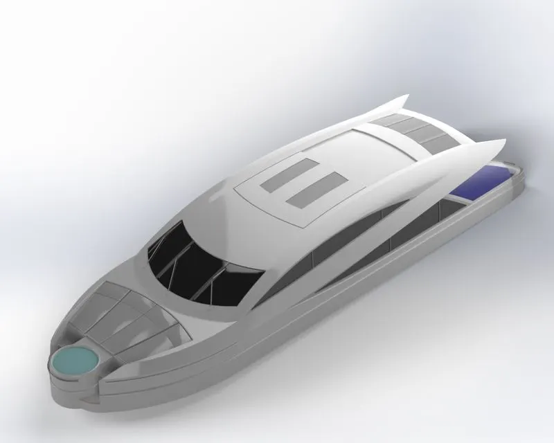
A superstructure is an upward extension of an existing structure above a baseline called ground level and it usually serves the purpose of the Structure's intended use. A superstructure is a decked structure on the free board deck, extending from side to side of the ship.
Features used
Convert entities
Mirror entities
Offset
Trim
Split entities
Surface sweep
Surface knit
Project curves
Surface trim
Surface loft
3D sketch
Surface fill
Surface extends
Ruled surface
Extrude
Fillet
Extrude cut
GARAGE DOOR
A garage door is a large door on a garage the opens either manually or by an electric motor [a garage door opener]. Garage doors are frequently large enough to accommodate automobiles and other vehicles. The operating mechanism is spring-loaded counterbalanced to offset the weight of the door and reduce human or motor effort required to operate the door. Less commonly, some garage doors slide or swing horizontally. Doors are made of wood, metal, or fibre glass, and may be insulated to prevent heal loss.
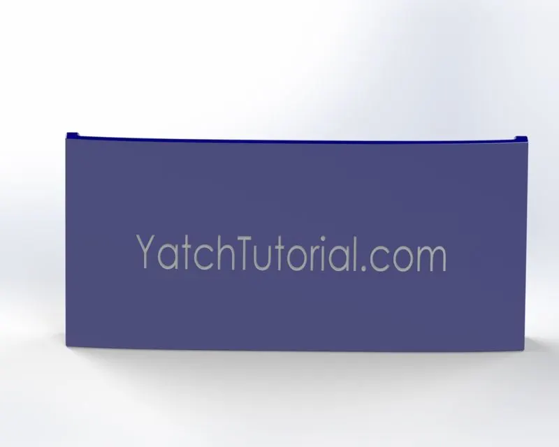
Features used
Text
extrude cut
Reference plane
Fillet
Shell
Mirror
RADAR
Marine radars are X band or S band radars on ships, used to detect other ships and land obstacle, to provide bearing and distance for collision avoidance and navigation at sea They are electronic navigation instruments that use a rotating antenna to sweep a narrow beam of microwaves around the water surface surrounding the ship to the horizon, detecting targets by microwaves reflected from them, generating a picture of the ship ‘s surroundings on a display screen.
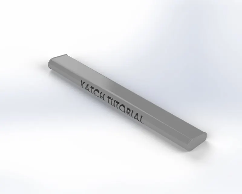
Features used
Extrude boss/base
Extrude cut
Sketch pattern
Fillet
Mirror
Split line
PROPELLER
A propeller is a device with a rotating hub and radiating blades that are set at a pitch to form a helical spiral, that, when rotated, performs an action which is similar to Archimedes' screw. It transforms rotational power into linear thrust by acting upon a working fluid, such as water or air.
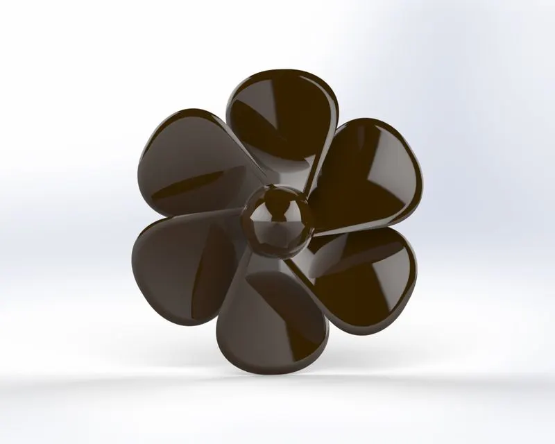
Features used
Revolved boss/base
Lofted boss/base
Extrude cut
Reference plane
Circular pattern
Fillet
RADAR MAST
A mast is a vertical ship structure mounted on top of bridge and ton/yard of the forecastle towards the ship ‘s pow. let accounts for the support platform for the ships derrick and hold necessary equipment's such as radars, navigation light and ships horn in case of foremost They are made of high tensile steel with added rigidity based on the size of derricks it holds. Other than that, a ships main most is also used to hoist ships flag. Out of different parts of ship the main job of mast is to hold necessary equipment such as radar receiver, navigation lights. ships horn, flags in some case.
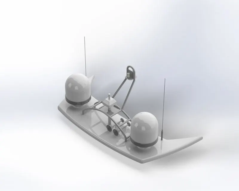
Features used
Revolved boss/base
Extrude boss/base
Swept boss/base
Mirror
dome
Lofted boss/base
Extrude cut
Reference plane
Circular pattern
Fillet
FRONT SEAT
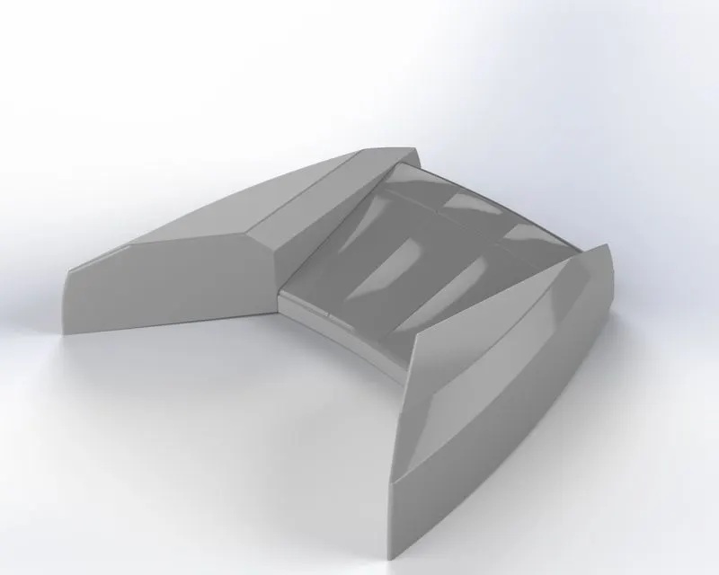
Front seat feature Two connected seals That are built back-to-back horn one and other. They have a building storage unit underneath Them. Lounge seats can also fully recline right back to make it easier for you to kick your feet up and get more comfortable. The front seat in our model was placed before the superstructure and also H has sun pads to rest on is Sun pads are a great way to reclaim lost space on our Boat.
Features used
Convert entities
extrude boss/base
Revolve boss/base
Extrude cut
Fillet
Dome
mirror
MIDDLE SEAT
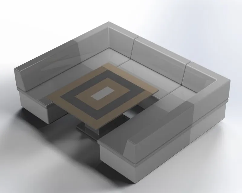
The middle seat in our model was placed just behind the superstructure. It is provided with a luxury table to dine out. it can also be used to have casual meetings with co passengers.
Features used
Convert entities
extrude boss/base
Revolve boss/base
Extrude cut
Fillet
Dome
mirror
REAR SEAT
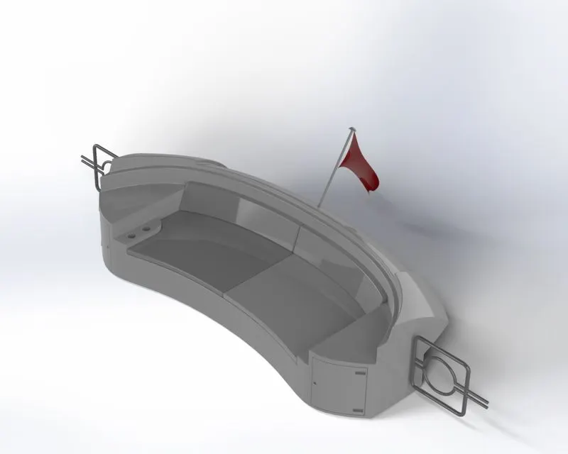
The rear seat was placed at the end of the deck surface. The rear seat consists of locker racks and steel doors for our stairs. The flag was also placed behind the rear seat since ifs the end part of our yacht. To have a nice view from the yacht while having drink the rear seat was also provided with a slot to rest the gloss or mug.
Features used
Convert entities
Offset entities
Trim entities
Extrude boss/base
Offset surface
Ruled surface
Trim surface
Knit surface
ASSEMBLED SUNSEEKER PREDATOR YATCH
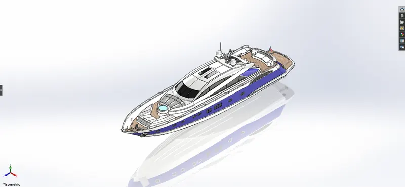
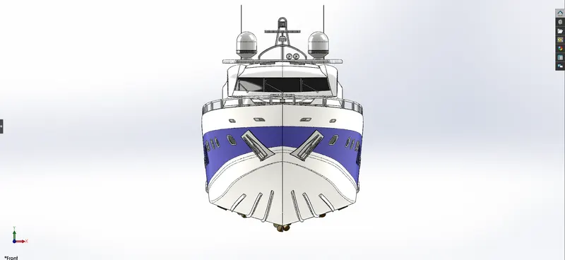
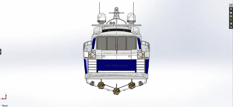
Assembly is most often referred to putting components together in an assembly line, but more specifically, it refers to creating a complete product that performs an intended function. Changes in the component are automatically reflected in the assembly i.e. The rebuild option will automatically take place or else it will ask the user to rebuild the document.
ISOMETRIC VIEW:
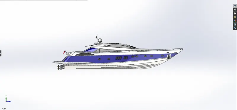
LEFT SIDE VIEW:
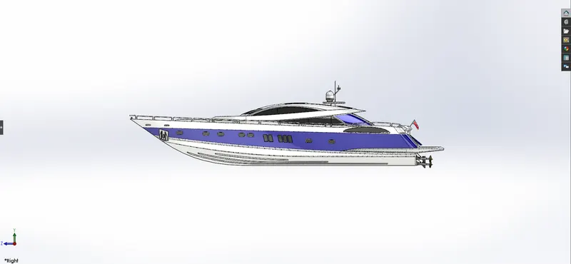
RIGHT SIDE VIEW:
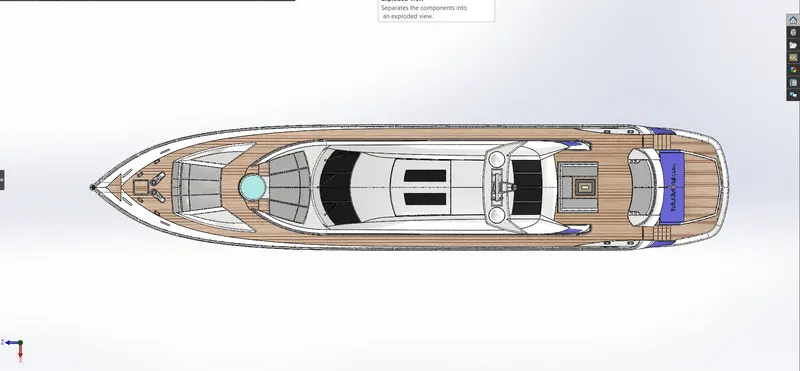
TOP VIEW:
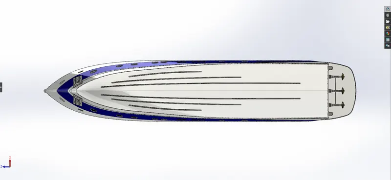
BOTTOM VIEW:
FRONT VIEW:
BACK VIEW:
The Sunseeker Predator Yatch is assembled using the feature called mates. Each and every part is mated with the other or the base part with specific relation. Some relations that are used to mate the parts of Yatch are mentioned below,
- Concentric
- Coincident
- Parallel
- Width
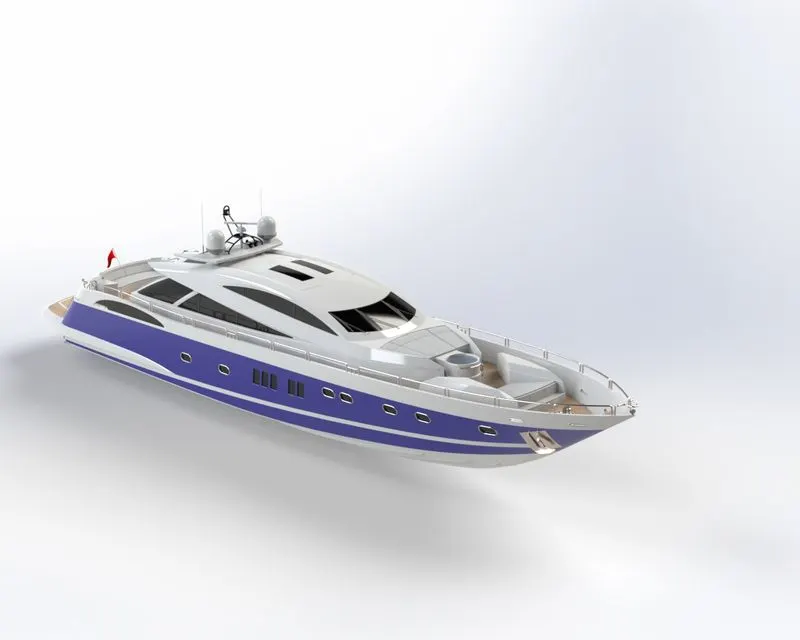
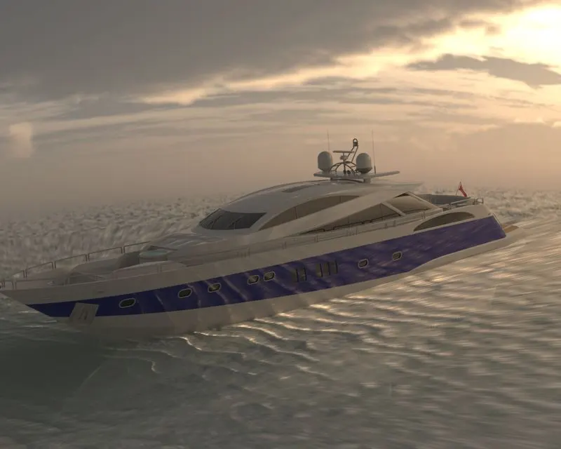
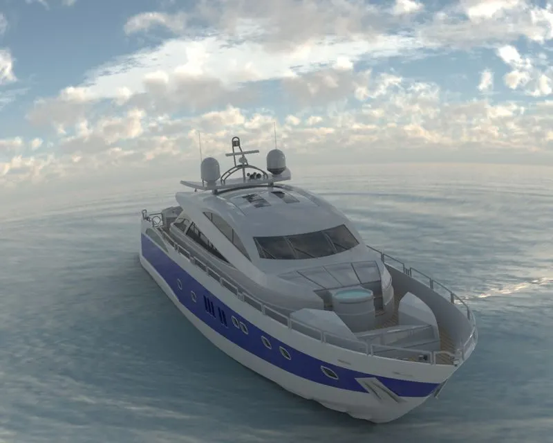
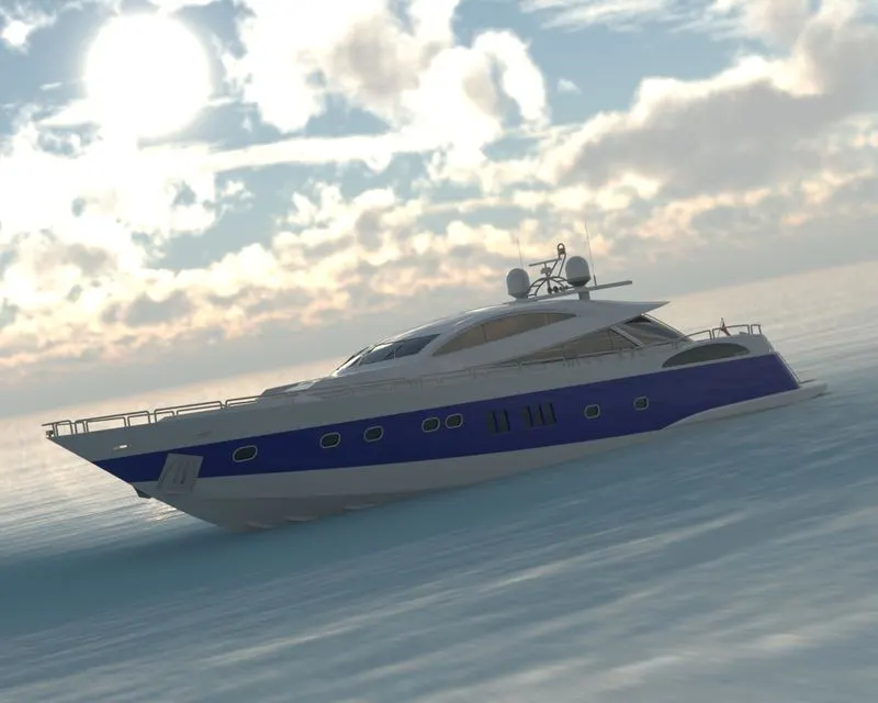
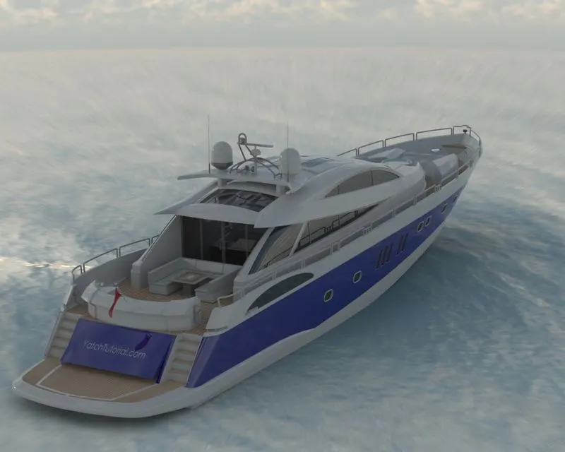
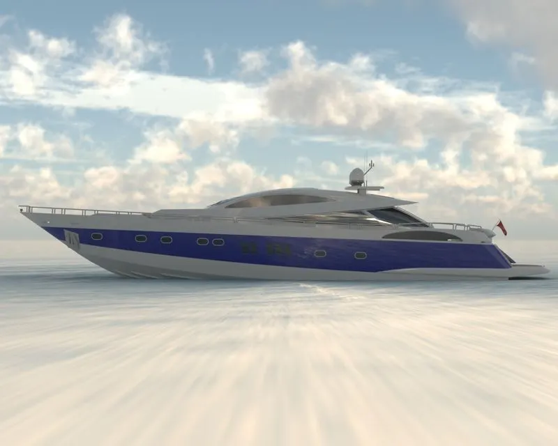
FINAL RENDERS OF SUNSEEKER PREDATOR YATCH
CONCLUSION
Thus, the parts of the SUNSEEKER PREDATOR YATCH are designed and assembled using SOLIDWORKS and are rendered to photorealistic images using PHOTOVIEW 360 and SOLIDWORKS VISUALIZE.
Note:Guided by Mr.Sabarishwaran
ZIPFILE LINK
ASSEMBLY OF YATCH WITH PARTS:https://drive.google.com/file/d/1gavM5R_S-YLDz0fSWAhEzwoBRydwOJ-m/view?usp=sharing
RENDERED ASSEMBLY OF YATCH:https://drive.google.com/file/d/1WKeGhhupqgNxUd4PeTV2uPTtohJLDF_g/view?usp=sharing