Advanced Sheet Metal Design Using NX Cad Challenge_5_Odd Shaped Enclosure
DESIGN OF ODD SHAPED ENCLOSURE IN SHEET METAL USING SIEMENS NXCAD
OBJECTIVE
To design odd shaped enclosure in sheet metal application under given geometry and measurements using the SIEMENS NXCAD software
INTRODUCTION
Sheet metal is metal formed by an industrial process into thin, flat pieces. Sheet metal is one of the fundamental forms used in metalworking, and it can be cut and bent into a variety of shapes. Countless everyday objects are fabricated from sheet metal. Thicknesses can vary significantly; extremely thin sheets are considered foil or leaf, and pieces thicker than 6 mm (0.25 in) are considered plate steel or "structural steel".
DESIGN METHODOLOGY
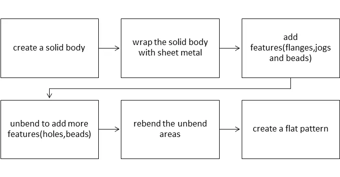
The design methodology of the odd shaped enclosure is explained with the help of flow chart for easy and better understanding
FLOWCHART
DESCRIPTION
There are various tools used to design the odd shaped enclosure in the sheet metal application in SIEMENS NXCAD they are described as follows,
Features Used
Tab: Creates a base feature by extruding a sketch along a vector by a thickness value, or adds material to a planar face. Additional planar selection can be added to generate bends as parts of the base feature.
Bending: Modifies the model by bending material on one side of a sketch line, adding a bend between the two sides.
Flanges: Adding a flat flange at an angle to a planar face and adds a bend between the two
Hem Flange: Modifies the model by folding the edge of a sheet metal flange over onto itself for the purpose of safe handling or to increase edge stiffness.
Jog: Modifies the model by lifting material on one side of a sketch line, adding a flange between the two sides
Breaking Corner: Rounds or chamfers a sharp corner of a tab or flange
Closed Corner: Closes a corner where two adjacent flanges meet by extending the bends and flanges.
Mirror Feature: Copies and mirrors it across a plane.
Mirror Body: Creates Associative copies of bodies, faces, curves, points and datums, and associative mirrored copies of bodies, within the same part.
Unite: Combines the volume of two or more solid bodies into a single body.
Unbend: Flattens a bend and the material adjacent to the bend
Hole: Adds a hole to one or more solid bodies in a part or assembly with options for counterbored, countersunk, and threaded.
Dimple: Lifts an area of the model inside a sketch that stimulates a stamping tool.
Beads: Lifts material along the contour of a sketch that stimulates a stamping tool
Datum Plan: Creates a datum plane used to construct other features.
Re-bend: Restores an unbend feature to its previous bent state, along with any features added after the unbend feature.
Flat Pattern: Creates a flat pattern feature from the formed sheet metal part
Drafting: Starts the drafting application, which provides tools to create and maintain drawings of the design model.
PROCEDURE
Create a solid body that encompasses the interior volume of the final enclosure shape, using tools in the modeling application. Use the sheet metal from solid command to wrap the solid body with sheet metal. Add features such as flanges, jogs, or bends, to further define the basic shape of the formed sheet metal part. Unbend the bend areas where needed, and place holes, cutouts, beads, dimples, or louver features on the part. Re-bend the flattened bend areas to complete the part. Create a flat pattern of the part for drafting and later manufacturing.
PART IMAGES
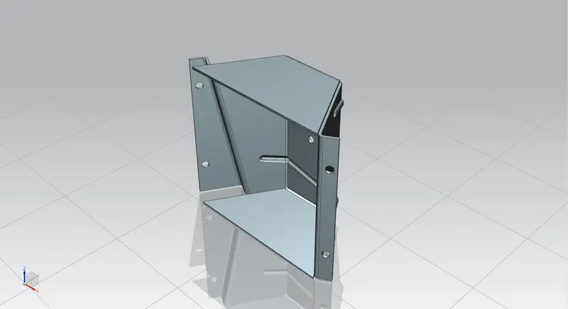
Isometric View:
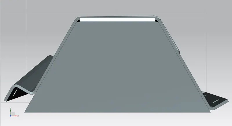
Top View:
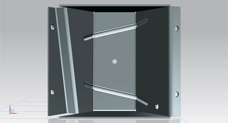
Front View:
Right Side View:
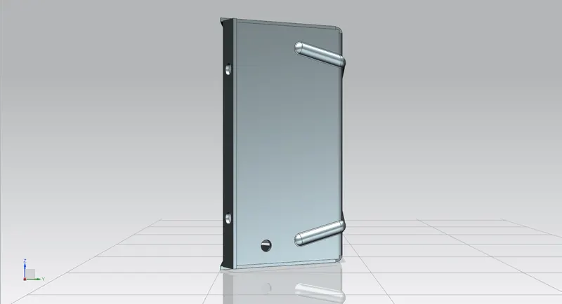
Bottom View:
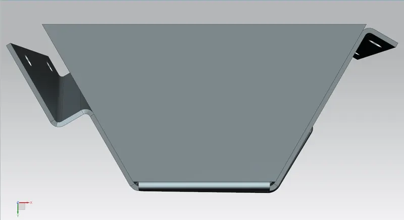
Back View:
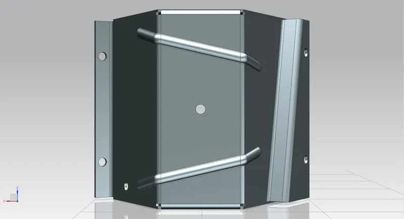
Left View:
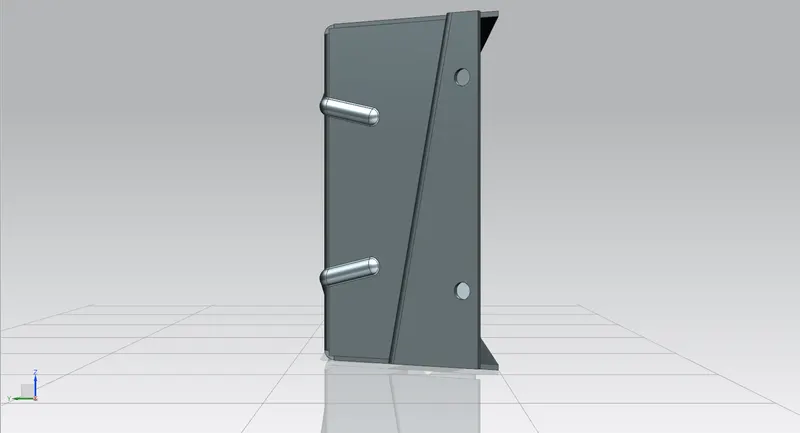
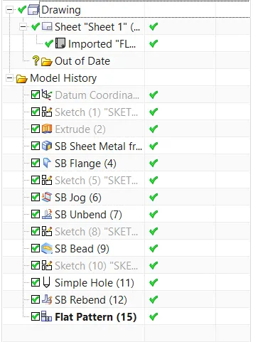
Model Tree:
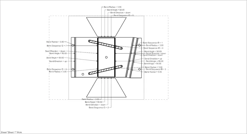
Detailed Drawing Sheet:
CONCLUSION
The odd shaped enclosure is designed using the Sheetmetal application in the SIEMENS NXCAD.
Link:https://drive.google.com/file/d/1EtrM2lTcovrr_HoS1VGQ0wAt-2gtJHuM/view?usp=sharing