Advanced Sheet Metal Design Using NX Cad Challenge_1_Casing Design
DESIGN OF CASING IN SHEET METAL USING SIEMENS NXCAD
OBJECTIVE
To design casing in sheet metal application under given geometry and measurements using the SIEMENS NXCAD software
INTRODUCTION
A Casing is a Sheetmetal component used as cover or a shell that protects component on which it is used with. Generally, a casing is a protector or a cover to hide the interior working objects to make the product simple and make ease of access.
DESIGN METHODOLOGY
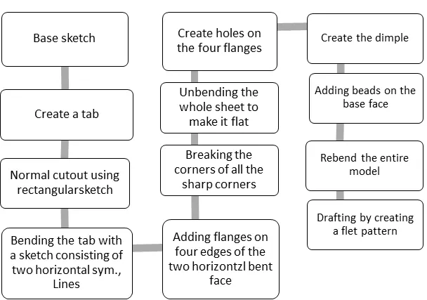
The design methodology of the casing is explained with the help of flow chart for easy and better understanding
FLOWCHART
DESCRIPTIION
There are various tools used to design the casing in the sheet metal application in SIEMENS NXCAD they are described as follows,
Features Used
Tab: Creates a base feature by extruding a sketch along a vector by a thickness value, or adds material to a planar face. Additional planar selection can be added to generate bends as parts of the base feature.
Normal cutout: Cuts material by projecting a sketch onto the model and then cutting perpendicular to the faces intersected by the projection
Bending: Modifies the model by bending material on one side of a sketch line, adding a bend between the two sides.
Flanges: Adding a flat flange at an angle to a planar face and adds a bend between the two
Breaking Corner: Rounds or chamfers a sharp corner of a tab or flange
Unbend: Flattens a bend and the material adjacent to the bend
Hole: Adds a hole to one or more solid bodies in a part or assembly with options for counterbored, countersunk, and threaded.
Dimple: Lifts an area of the model inside a sketch that stimulates a stamping tool.
Beads: Lifts material along the contour of a sketch that stimulates a stamping tool
Rebend: Restores an unbend feature to its previous bent state, along with any features added after the unbend feature.
Flat Pattern: Creates a flat pattern feature from the formed sheet metal part
Drafting: Starts the drafting application, which provides tools to create and maintain drawings of the design model.
PROCUDRE
- A sketch is drawn in a respective plane
- It is extruded in to a base using the command tab
- Anormal cutout is made on the left edge of the base
- The top and bottom edges are bent using two horizontal line sketches
- Flanges are added at the four edges of the two bent surfaces
- Breaking corners are applied to all the sharp corners of the part
- The sheet metal is unbent
- Holes are added at the four flanges symmetrical to the x axis
- A dimple is created on the base surface with a sketch drawn
- Bead is created on the on the base and are mirrored
- The sheet metal part is re-bent
- Flat pattern is created for the designed casing model
- Finally, it is drafted in a4 size sheet in 2:1 scale
PART IMAGES
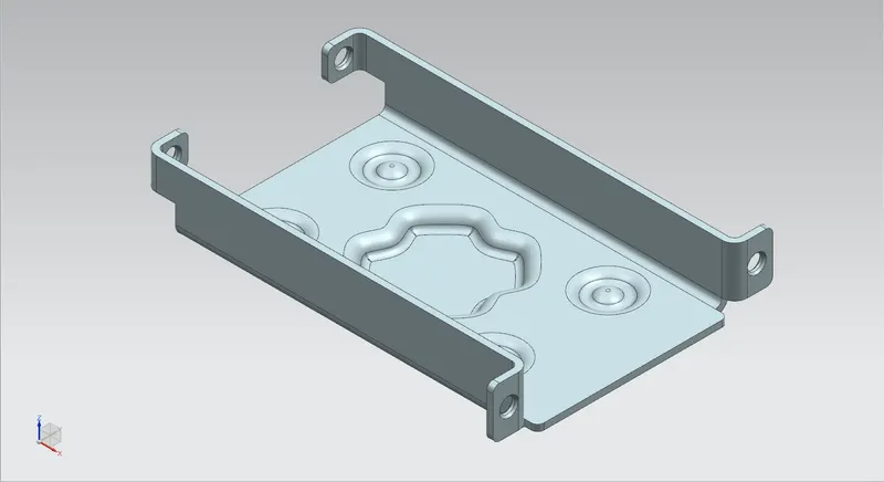
Isometric View:
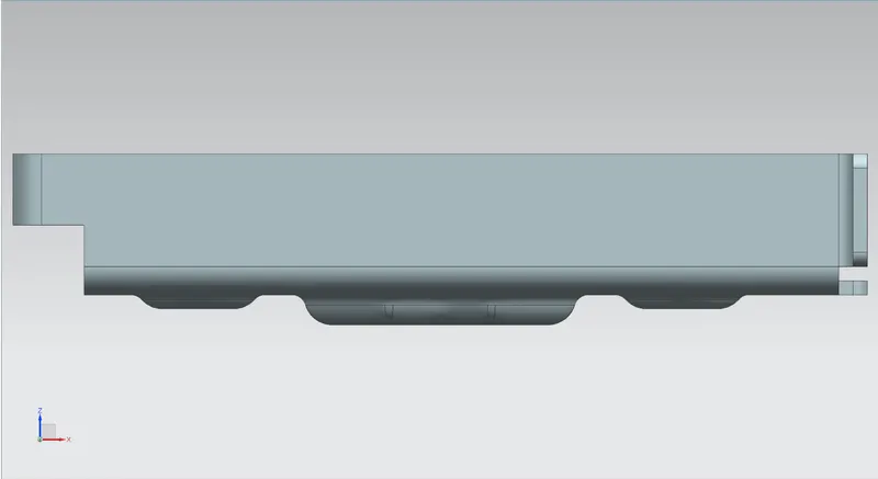
Front View:
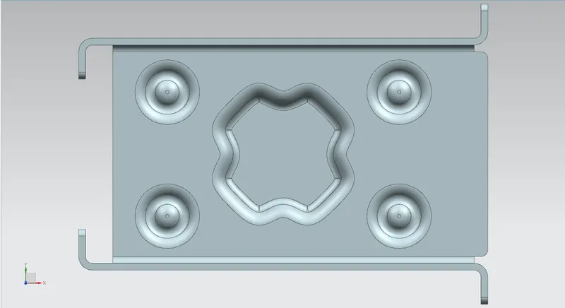
Top View:
Left Side View:
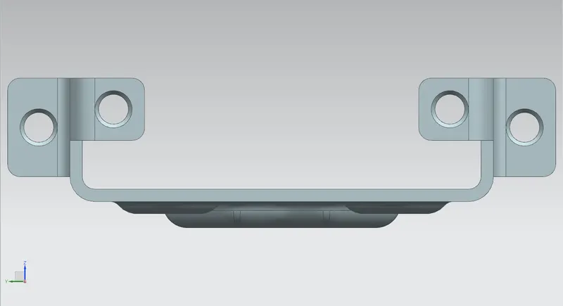
Back View:
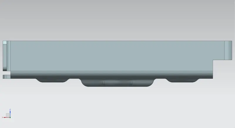
Bottom View:
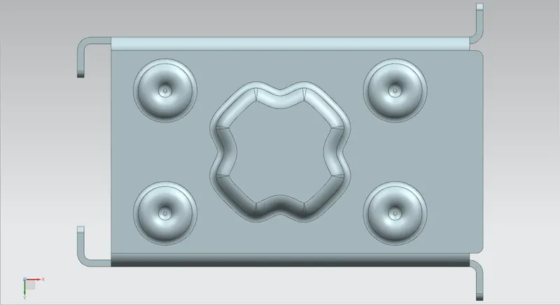
Right Side View:
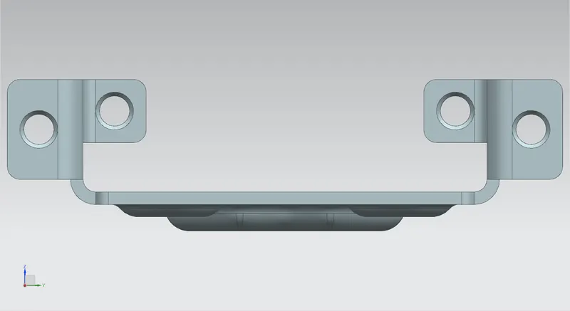
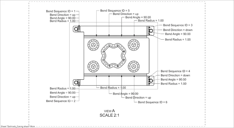
Detailed Drawing Sheet Image:
CONCLUSION
The casing is designed using the Sheetmetal application in the SIEMENS NXCAD.
Link:https://drive.google.com/file/d/1GJF41esyn6kKKbUhyBJfbn2gmX4G-3Wx/view?usp=sharing