Radar Mast & Final Assembly of Yacht
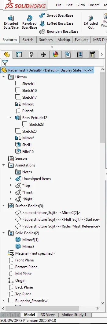 Feature Tree 01
 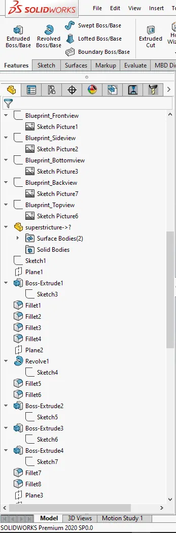 Feature Tree 02
 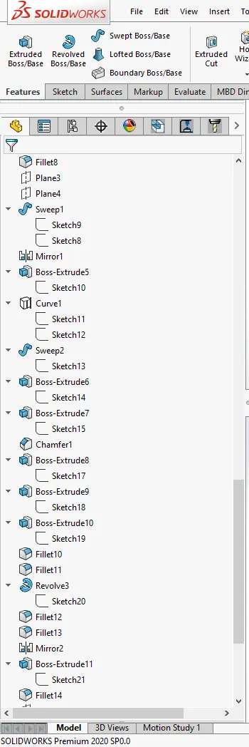 Feature Tree 03
 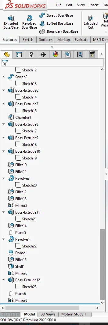 Feature Tree 04
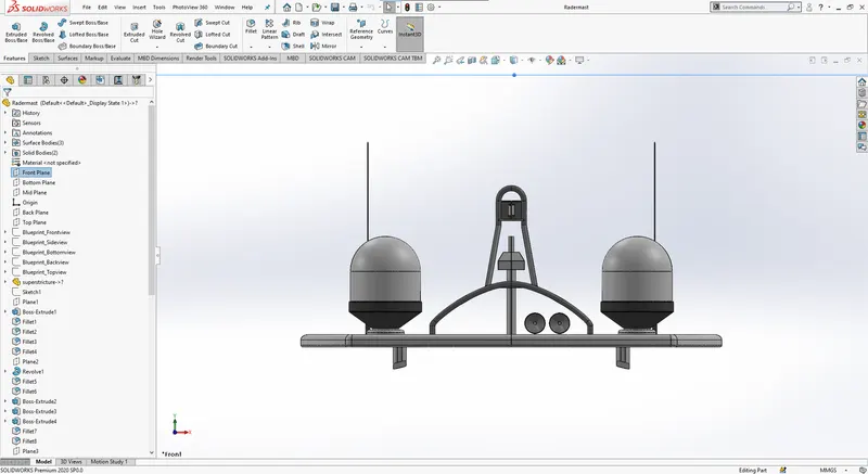 Front View
 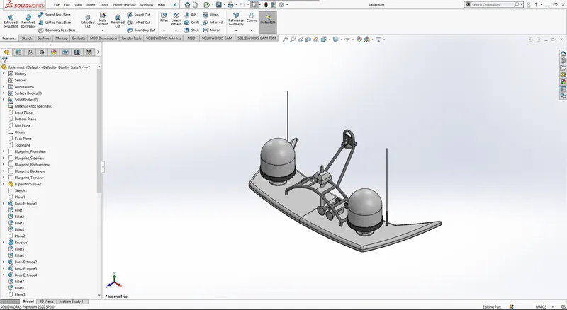 Isometric View
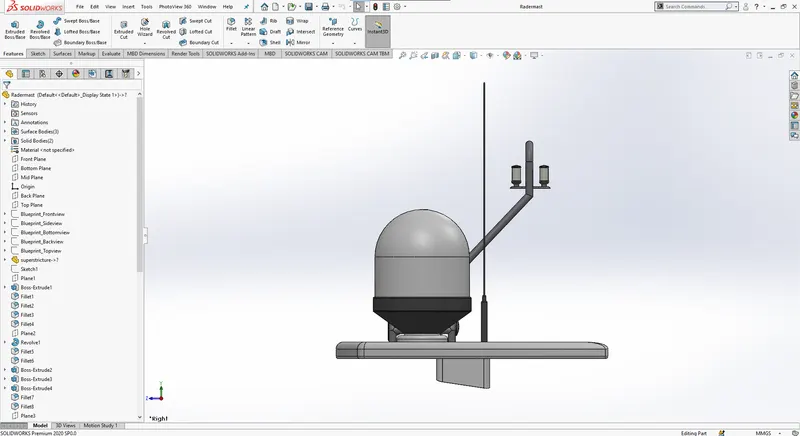 Side View
 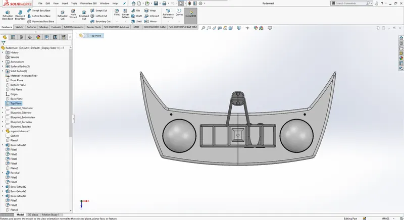 Side View
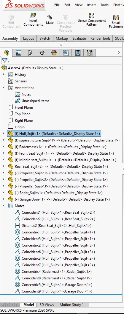 Feature Tree
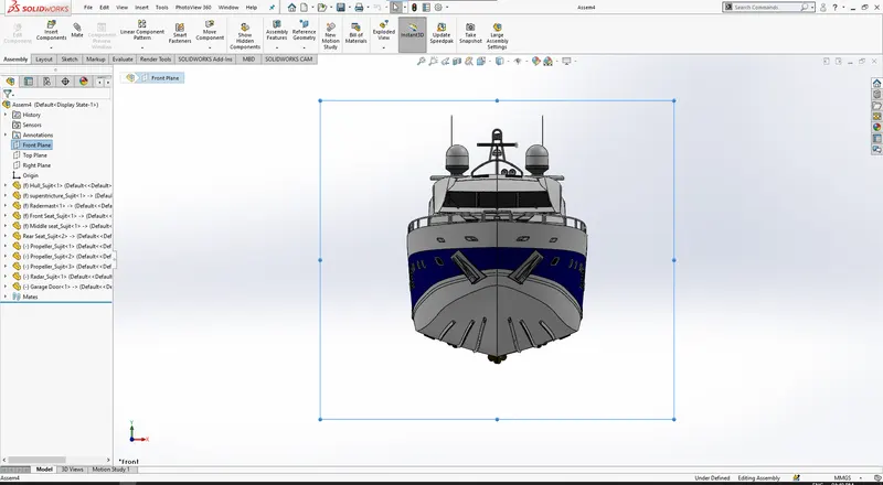 Front View
 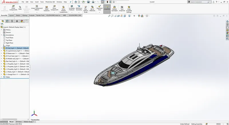 Isometric View
 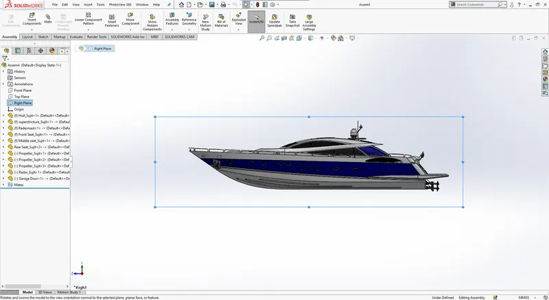 Side View
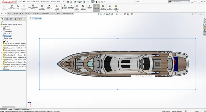 Top View
Design and Assembly of Yacht
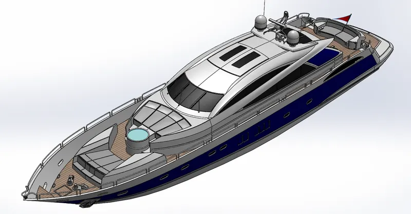
Objective:
- To get an understanding of different tools and commands available in Solidworks.
- To design the part of Yacht using Solidworks.
- To assemble all the parts of the using Solidworks.
Introduction:
- SolidWorks: A solid modelling computer-aided design and a computer-aided engineering computer program that runs primarily on Microsoft Windows.
- Modelling: The terminology, basic design concepts, and procedures that you must know before you start building parts.
- Assembling: Fitting together different parts to complete the model.
Design methodology:
- Every part of the chopper has to be designed separately to reduce the complexity and make changes if needed.
- Starting from the 2D drawing to simplify the process. 2D drawings are nothing but side view or top view or front view on the object.
- To design the product from different views and making a 3D model
- Bring together the parts and assembling them to get the final assembled model
- Following are a few Sketch options:-
| Sketch | To create a new sketch or edit an existing one. |
| Smart Dimensions | To get the dimensions for one or more entities in one go. |
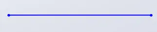
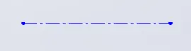
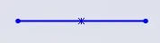
| Line |
To draw a line. Types-
|
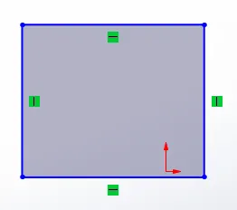
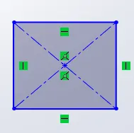
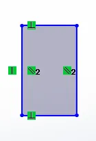
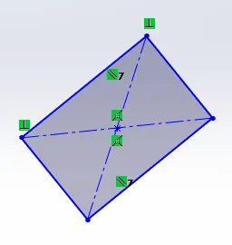
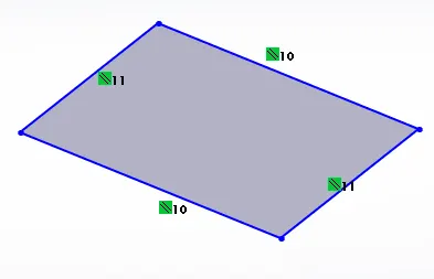
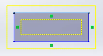
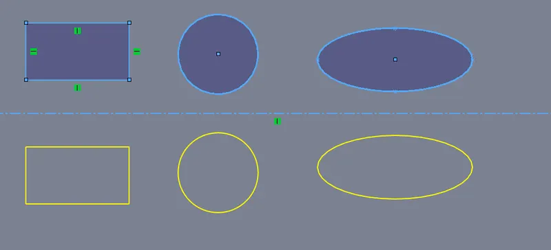
| Rectangle |
To draw rectangular fracture. Types-
|
| Circle | To draw a circle. 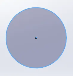 |
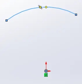
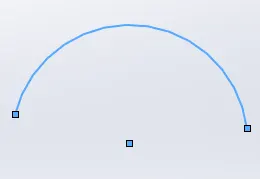
| Arc |
To draw an arc. Types-
|
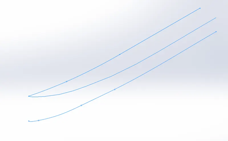
| Spline | To draw a curved path or profile. |
| Ellipse | To draw a complete ellipse.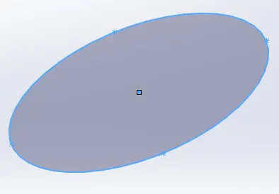 |
| Trim |
Help to trim or extend the entity using power trim. |
| Convert entities |
Converts selected edge and sketch identical entity by projecting on the sketch. |
| Offset entities |
Offset entities by a specific distance on one or both sides. |
- Following are some Features:-
|
Extrude Boss/Base |
Extrude the sketch in one or two directions to create a solid feature, converting 2D into 3D. |
Revolve Boss/Base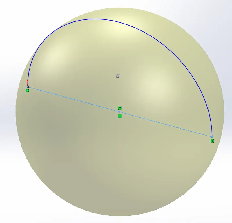 |
Revolve a sketch around an axis to create a sold feature, to obtain a spherical feature. |
Swept Boss/Base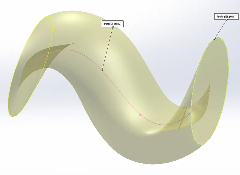 |
To move along the path created, to obtain complex parts. |
Lofted Boss/Base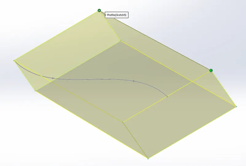 |
To add material between two or more profiles to create a solid feature. |
Extrude Cut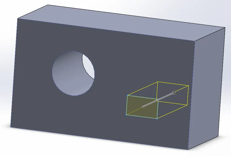 |
To remove the material from the 3D model. |
|
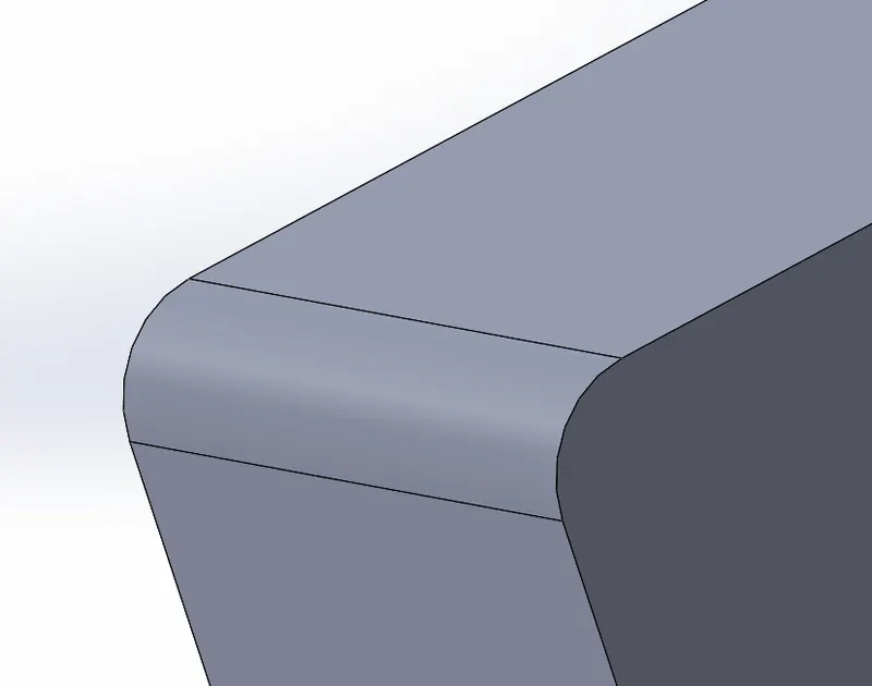
Fillet |
To create a rounded /curved face along the edge of the solid surface feature. Can be the same or variable size. |
|
Projected Curves |
To get the defined 3D curve with the help of 2D lines. |
|
Mirror |
To create a mirror image of faces, bodies about the axis, creating symmetry. |
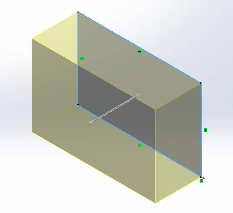
Parts of the Yacht:-
| Parts- | Function- | Feature Used- |
Front Seat-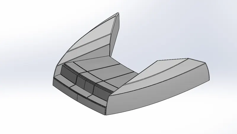 |
The relaxing area in the front section of the Yacht. |
Sketch |
Garage Door-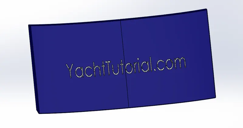 |
The door to enclose the garage. | Sketch Cut Extrude Shell Fillet Mirror |
Hull-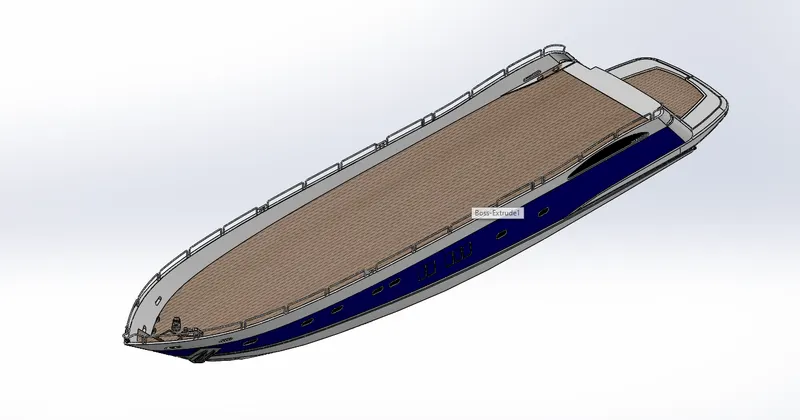 |
The hull of a ship is the most notable structural entity of the ship. |
Sketch, 3D Sketch |
Middle Seat-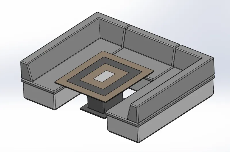 |
Placed At the rear of the superstructure for relaxing and having food. |
Sketch |
Propeller-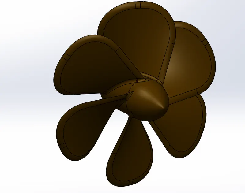 |
Propeller blades displace water, to create the forces that move a Yacht forward. | Sketch Revolve Loft Fillet Cut Extrude Pattern |
|
Radar- |
Radio Detection and Ranging, is used to detect objects and their position relative to your current location. |
Sketch |
Radar Mast-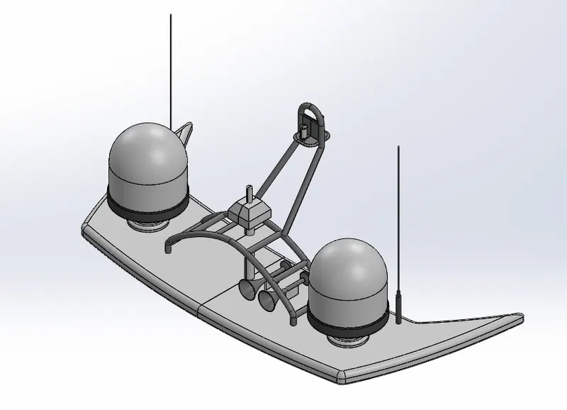 |
A marine radar device acts as a major navigation aid for boaters. |
Sketch |
Rear Seat-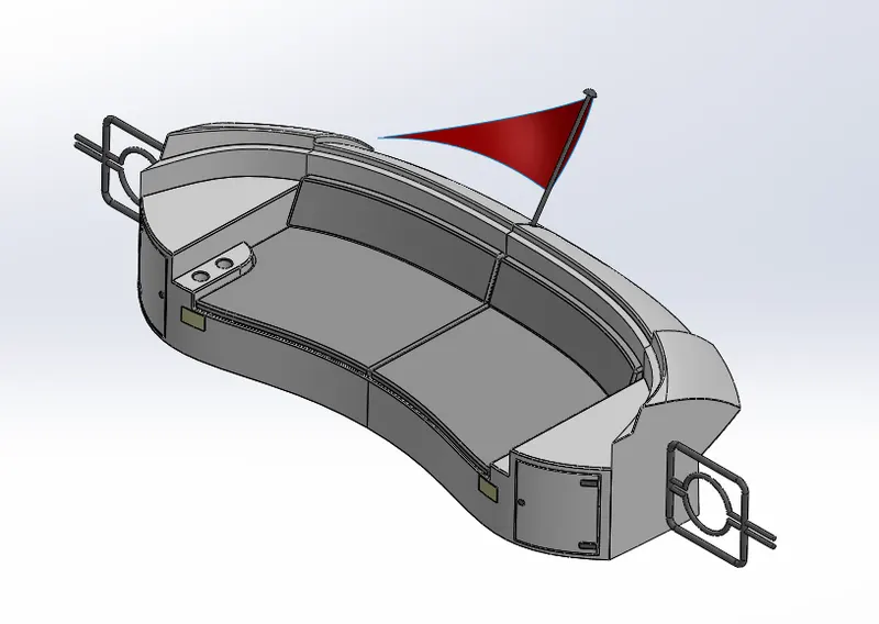 |
Placed at the rear of the Yacht for relaxing. | Sketch Surface Sweep Surface Offset Surface Trim Surface Knit Surface Loft Chamfer Fillet Sweep mirror Revolve |
Superstructure-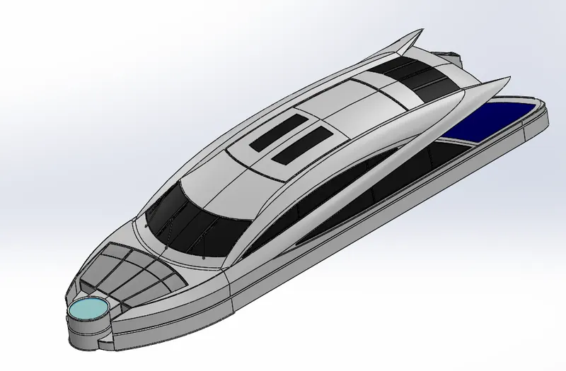 |
To add construction to an already existing structure, mostly designed in fashion as well. |
Sketch, 3D Sketch Surface Extrude Surface Knit Fillet Surface Trim Projected Curves Surface Loft Surface Sweep Cut Extrude Dome Fillet |
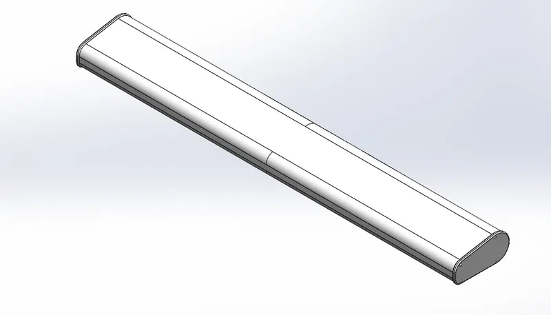
Assembly of Yacht:
- Fitting together different parts by using assembly file available in Solidworks.
- For the start, Hull is inserted and fixed.
- All the remaining parts will be inserted and placed with respect to Hull with the help of possible mates.
- Mates: It is a geometric relation between components. These are provided to place the part in the assembly as needed. The object can be completely fixed or can have some degree of freedom.
Isometric View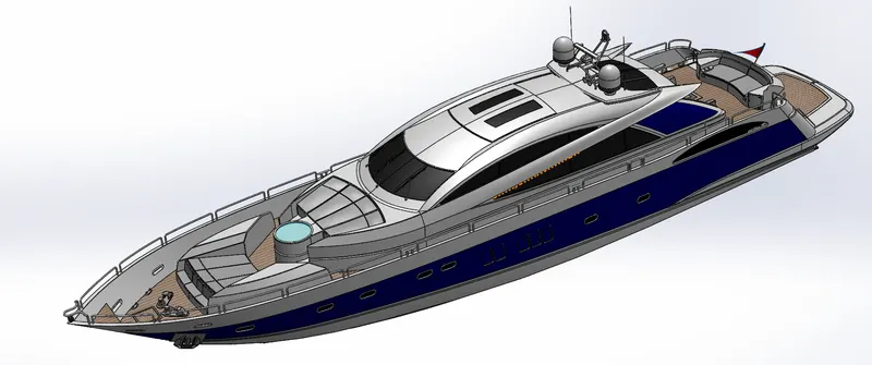
Front View Rear View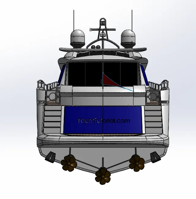
Side View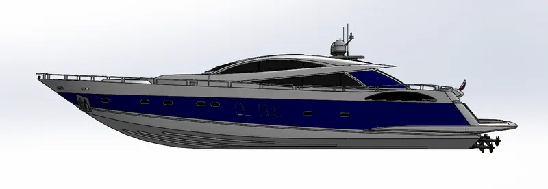
Top View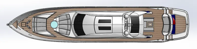
Rendered Images-
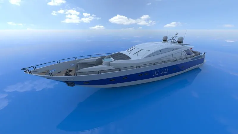
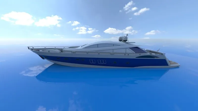
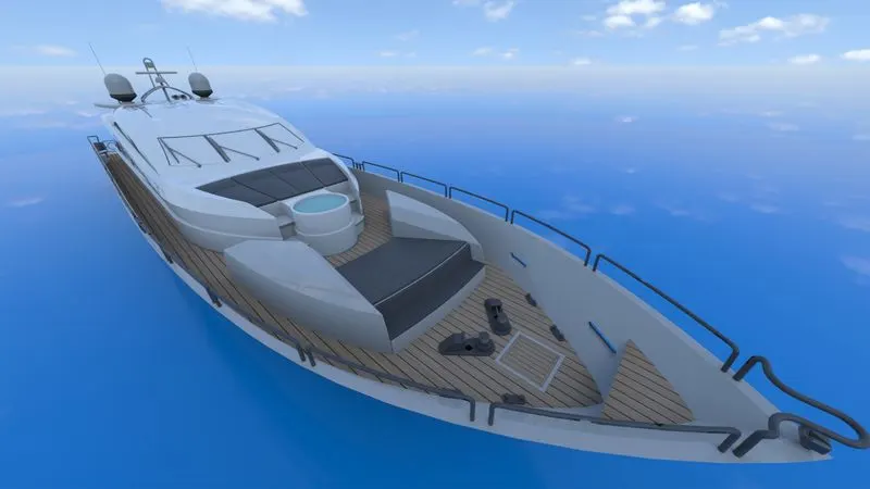
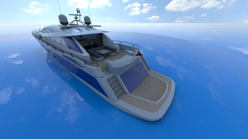
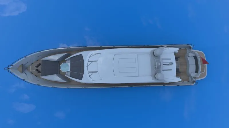
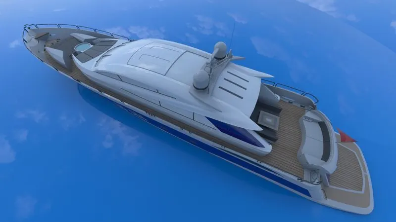
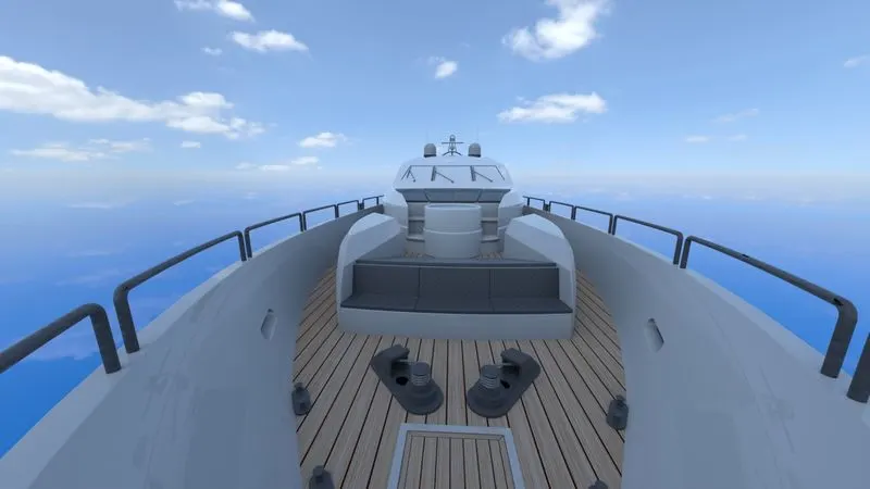
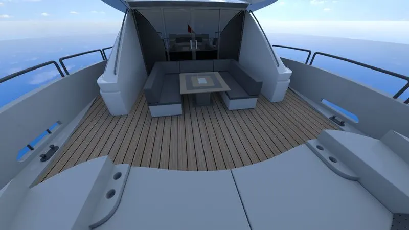
Conclusion:
- Learn to use Solidworks.
- Drawing the components with the help of different features.
- Assembling all the parts to complete the model.
- Giving the photo-realistic view with the help of Photo-view 360 and Solidworks Visualise.