American Chopper
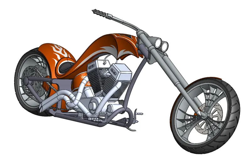
Design and Assembly of American Chopper
Objective:
- To get the understanding of different tools and commands available in Solidworks.
- To design the part of American Chopper using Solidworks.
- To assemble all the parts of the American Chopper using Solidworks
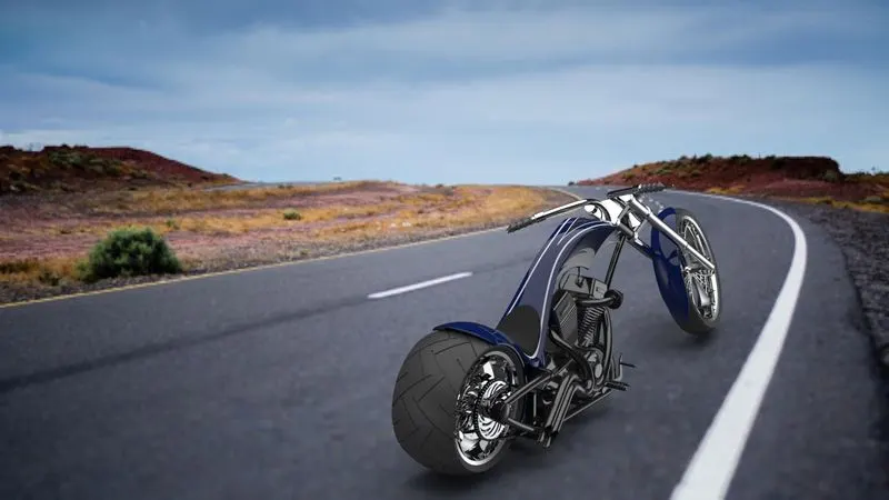
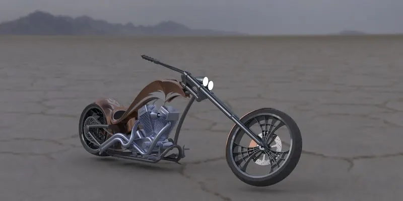
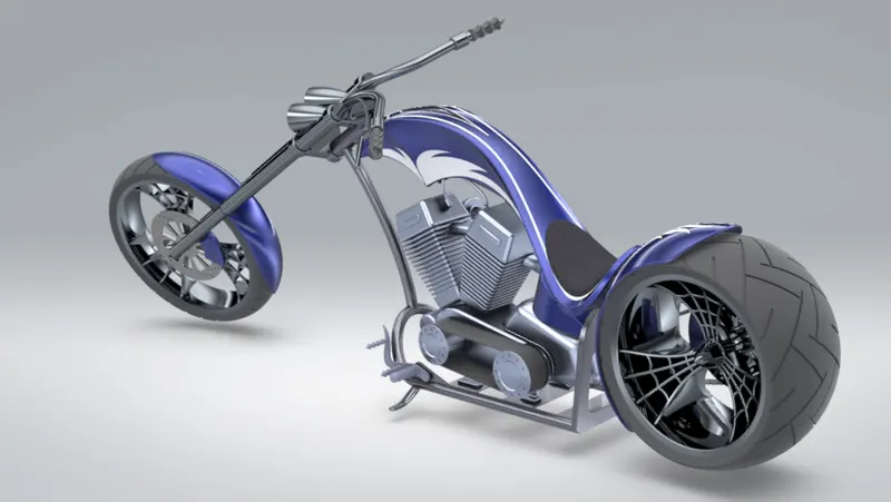
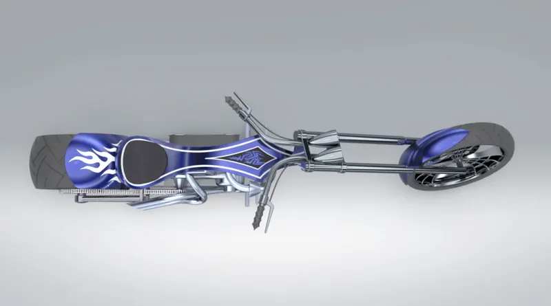
- To create a photo-realistic view, setting up camera view and lights for American Chopper using Solidworks Visualize.
Introduction:
- SolidWorks: A solid modelling computer-aided design and a computer-aided engineering computer program that runs primarily on Microsoft Windows.
- Modelling: The terminology, basic design concepts, and procedures that you must know before you start building parts.
- Assembling: Fitting together different parts to complete the model.
Design methodology:
- Every part of the chopper has to be designed separately to reduce the complexity and make changes if needed.
- Starting from the 2D drawing to simplify the process. 2D drawings are nothing but side view or top view or front view on the object.
- To design the product from different views and making a 3D model
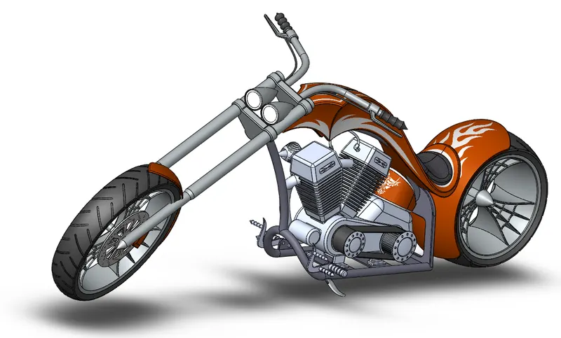
- Bring together the parts and assembling them to get the final assembled model
- Following are a few Sketch options:-
| Sketch | To create a new sketch or edit an existing one. |
| Smart Dimensions | To get the dimensions for one or more entities in one go. |
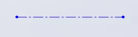
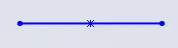
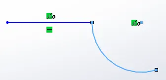
| Line |
To draw a line. Types-
|
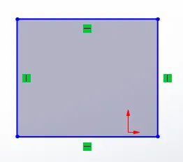
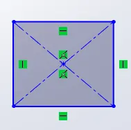
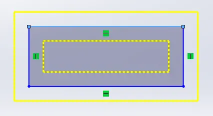
| Rectangle |
To draw rectangular fracture. Types-
|
| Circle | To draw a circle. 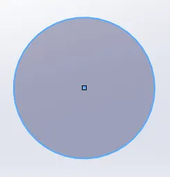 |
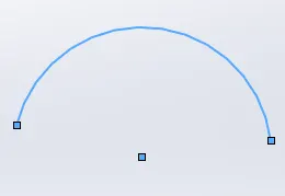
| Arc |
To draw an arc. Types-
|
| Spline | To draw a curved path or profile. |
| Ellipse | To draw a complete ellipse.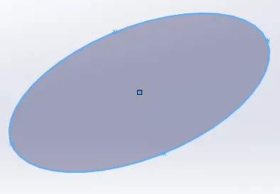 |
| Trim |
Help to trim or extend the entity using power trim. |
| Convert entities |
Converts selected edge and sketch identical entity by projecting on the sketch. |
| Offset entities |
Offset entities by a specific distance on one or both sides. |
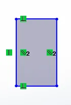
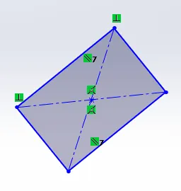
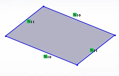
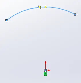
- Following are some Features:-
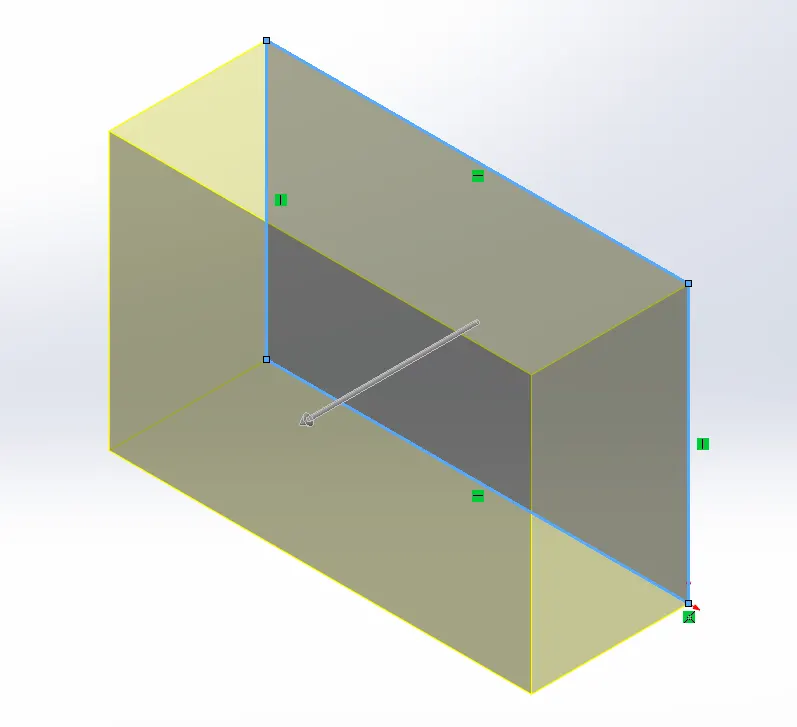
|
Extrude Boss/Base |
Extrude the sketch in one or two directions to create a solid feature, converting 2D into 3D. |
Revolve Boss/Base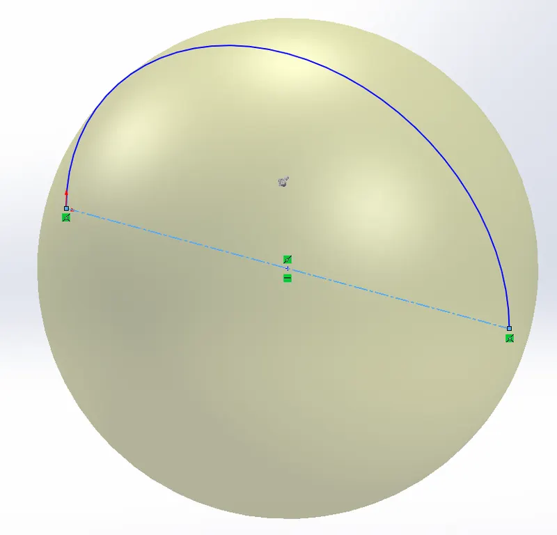 |
Revolve a sketch around an axis to create a sold feature, to obtain a spherical feature. |
Swept Boss/Base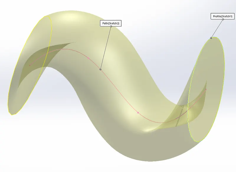 |
To move along the path created, to obtain complex parts. |
Lofted Boss/Base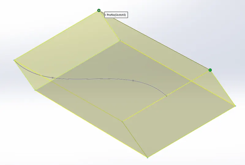 |
To add material between two or more profiles to create a solid feature. |
Extrude Cut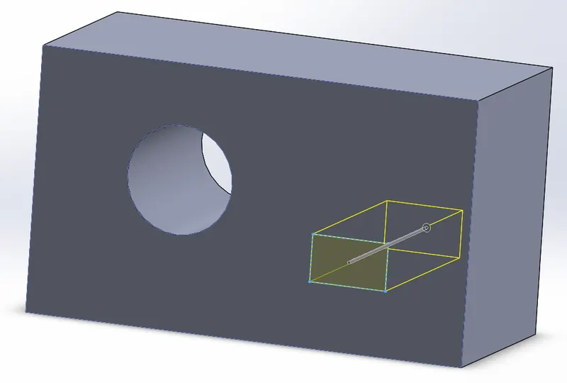 |
To remove the material from the 3D model. |
Revolve Cut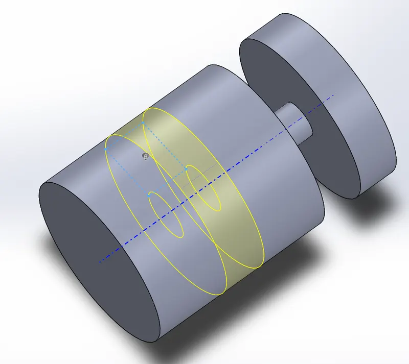 |
To remove the material around the axis or in a circular form 3D model. |
Swept Cut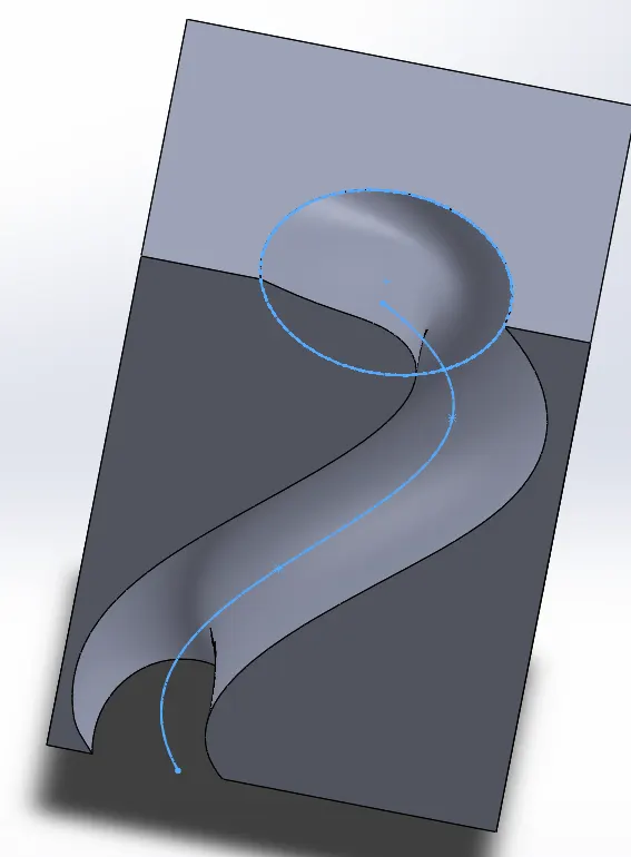 |
To cut the material by following a particular path. |
Lofted Cut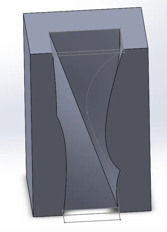 |
To remove the material between two or more profiles. |
|
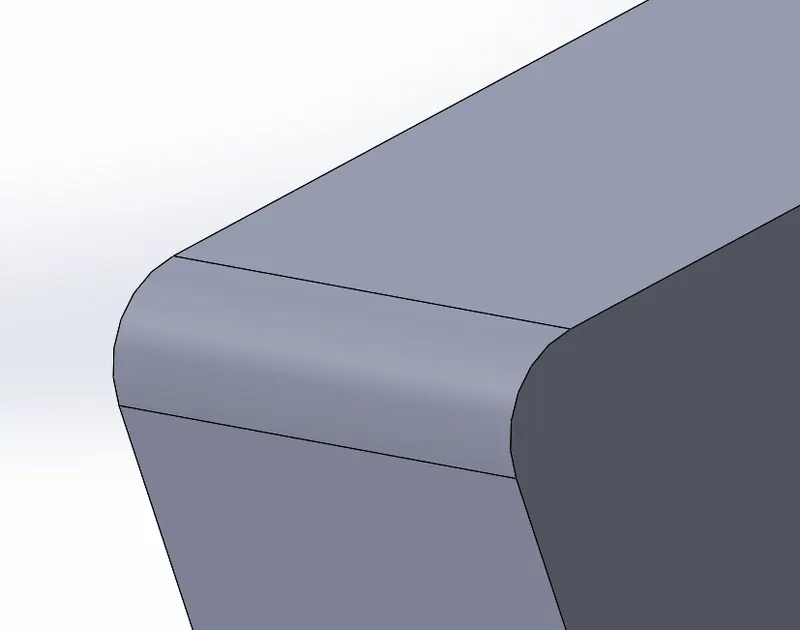
Fillet |
To create a rounded /curved face along the edge of the solid surface feature. Can be the same or variable size. |
|
Pattern |
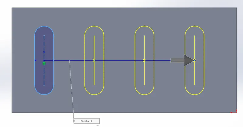
To pattern any kind of feature in one or two directions. Two types- Linear Pattern and Circular Pattern |
|
Mirror |
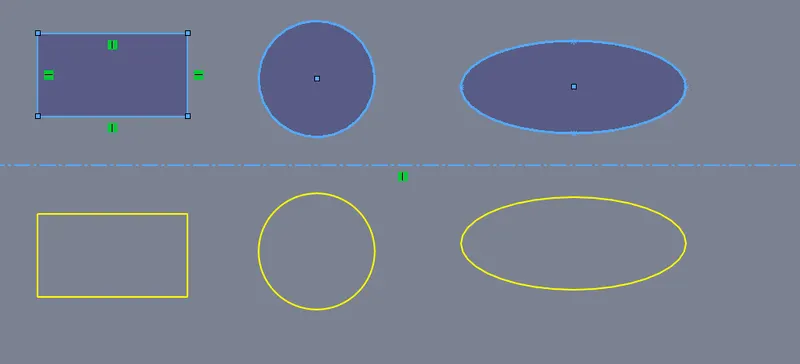
To create a mirror image of faces, bodies about the axis, creating symmetry. |
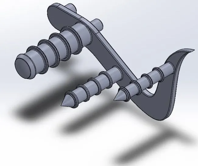
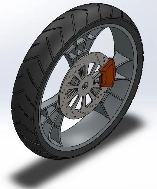
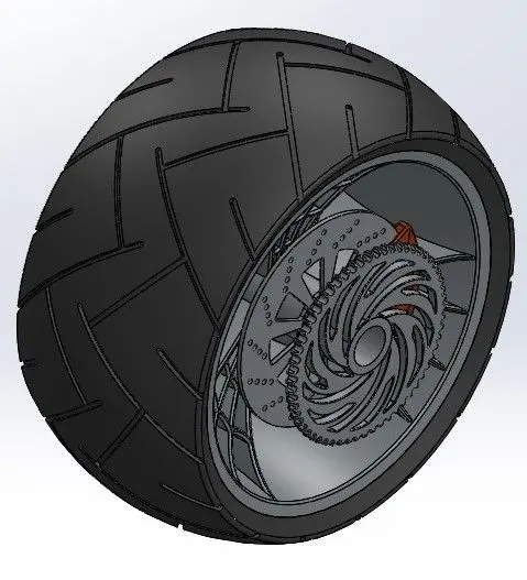
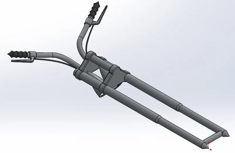
Parts of American Chopper:
|
Parts- |
Function- | Features Used to make- |
|
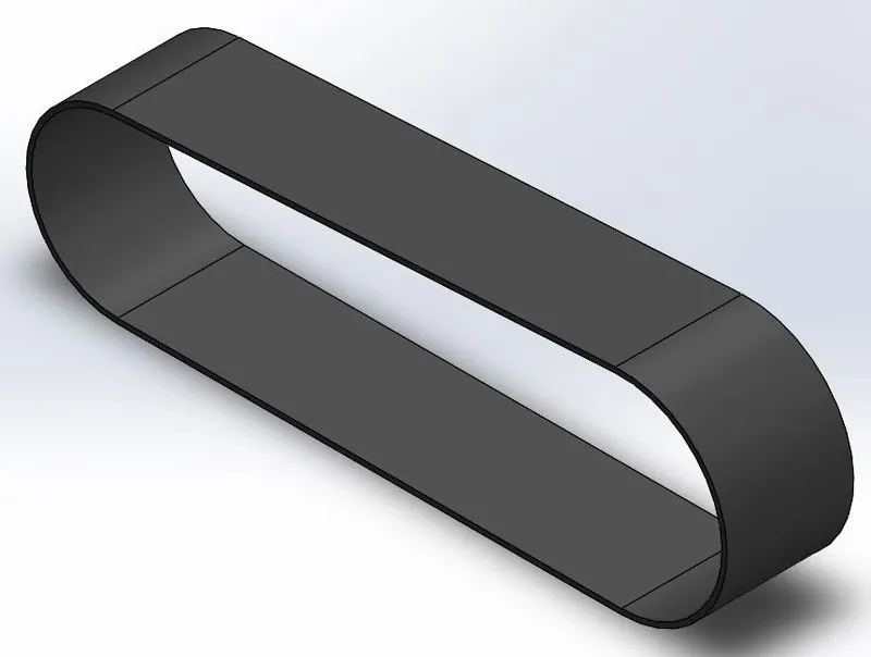
Transmission Belt |
|
|
|
Kick Stand |
|
|
|
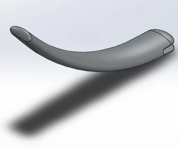
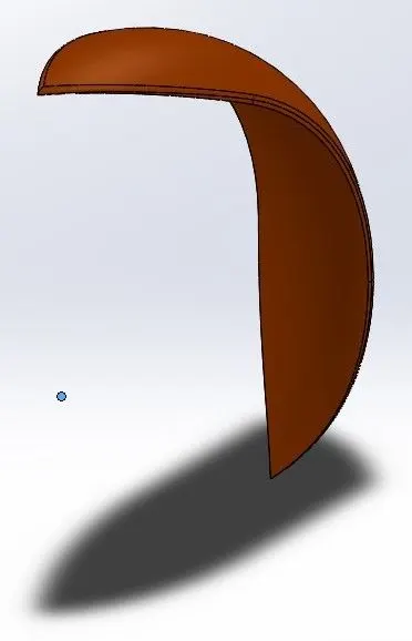
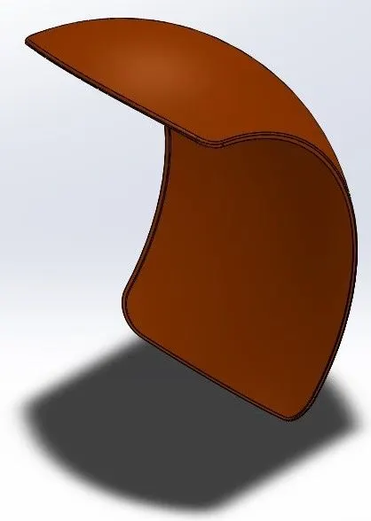
Front Fender |
|
|
|
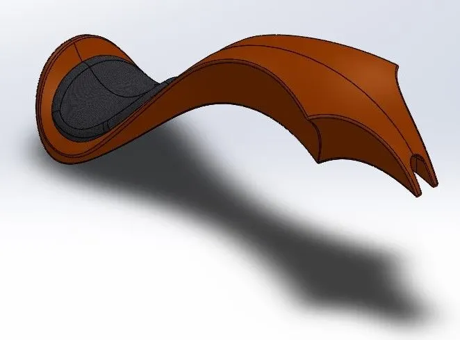
Rear Fender |
|
|
|
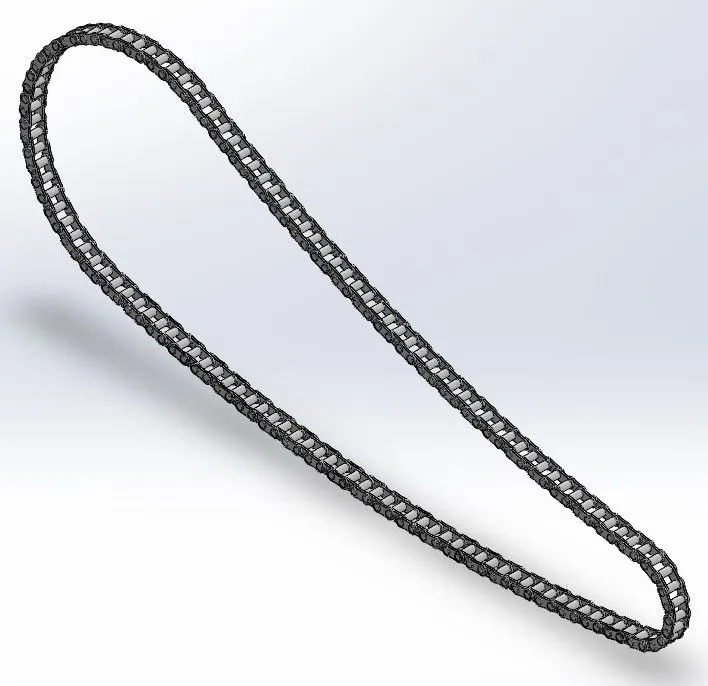
Chain |
|
|
|
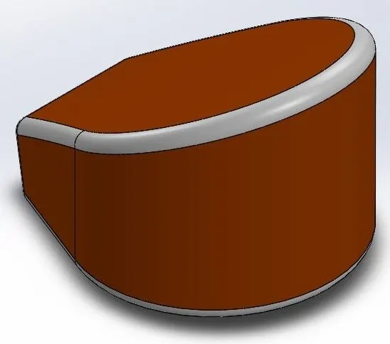
Oil Tank |
|
|
|
Pedal |
|
|
|
Front Wheel |
|
|
|
Rear Wheel |
|
|
|
Fork |
|
|
|
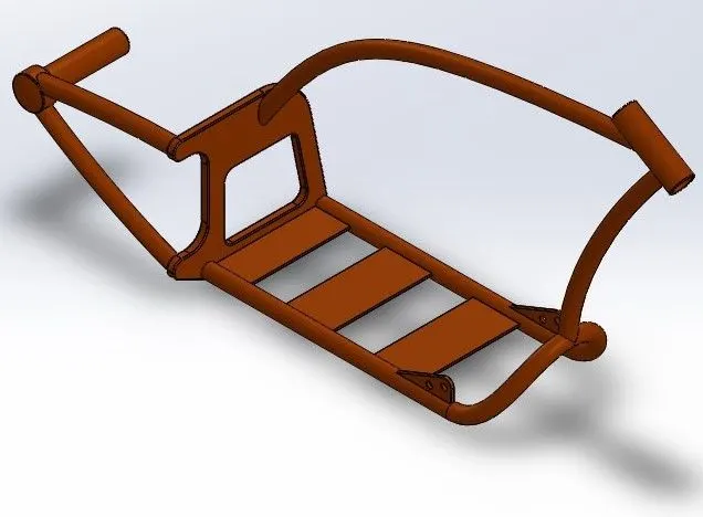
Chassis |
|
|
|
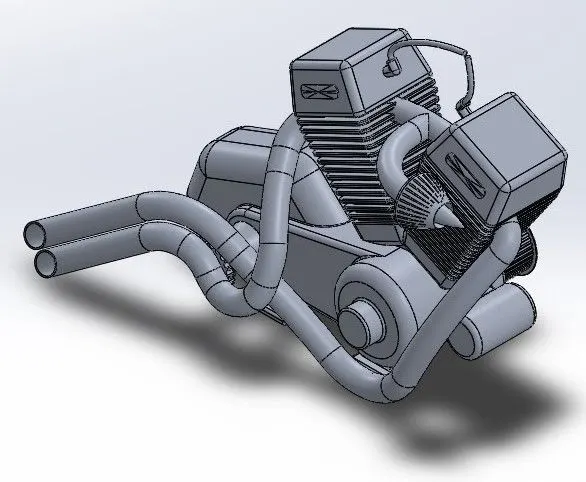
Engine |
|
|
|
Gas Tank |
|
|
Assembly of American Chopper:
- Fitting together different parts of the chopper by using assembly file available in Solidworks.
- For the start, Chassis is inserted and fixed.
- All the remaining parts will be inserted and placed with respect to chassis with the help of possible mates.
- Mates: It is a geometric relation between components. These are provided to place the part in the assembly as needed. The object can be completely fixed or can have some degree of freedom.
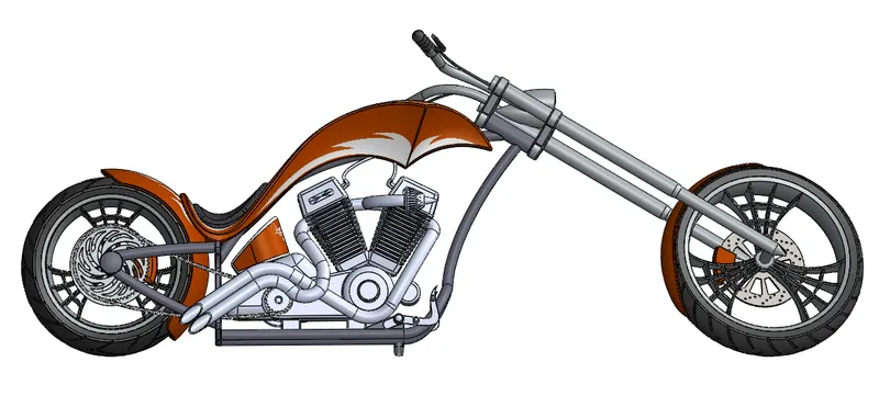 Side View
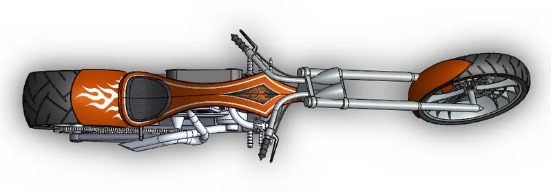 Top View
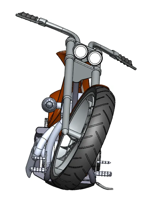 Front View
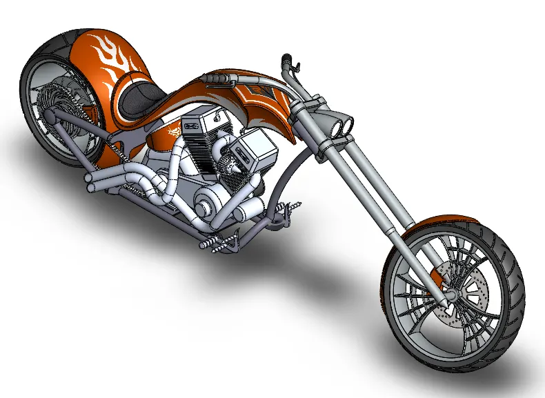 Isometric View
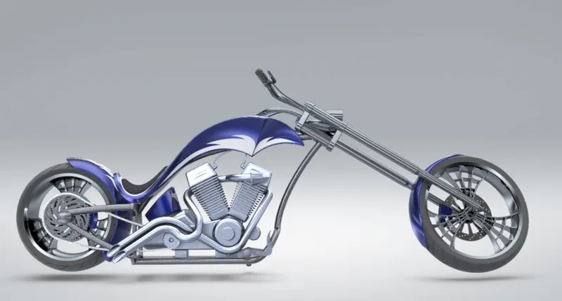
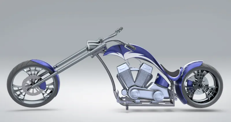
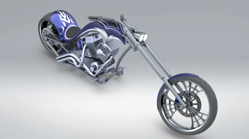
Rendering:
It is the process of generating a photorealistic or non-photorealistic image from a 2D or 3D model by means of a computer program.
It is carried with the help of SolidWorks Visualize.
Conclusion:
- Learn to use Solidworks.
- Drawing the components with the help of different features.
- Assembling all the parts to complete the model.
- Giving the photo-realistic view with the help of Photo-view 360 and Solidworks Visualise.