Radar Mast & Final Assembly of Yacht
Challenge-13
Radar Mast & Final Assembly of Yacht
Part Link of Radar Mast: -
- https://drive.google.com/file/d/18TmAAKM2NET_1SK_BPMCm7NnkdIKnadW/view?usp=sharing
Radar Mast -
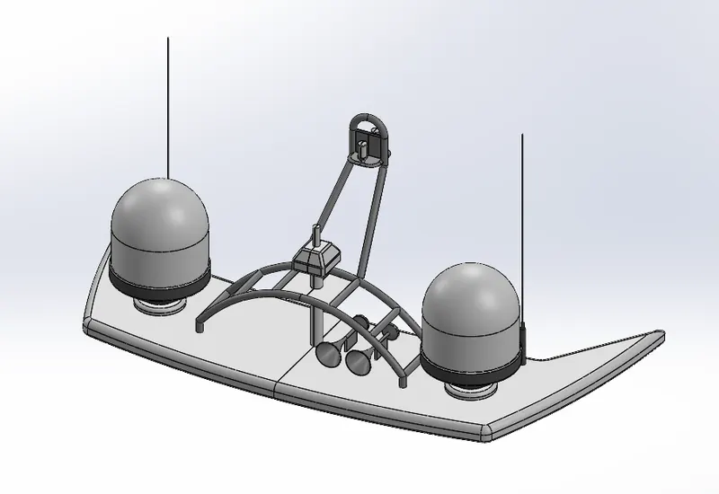
1. The Radar Mast has been created according to the dimensions.
2. Modeling of Radar Mast -
- Radar masts contain radar, antennas, satellite domes, and lights.
- The upper surface of the superstructure was designed as an interfacial surface.
- A radar mast is a yacht component that contains the vital electronics that connect to the radar and provide the signal it receives via the antenna and includes horns and lights.
- The radar mast is the mounting device of the radar in the ship.
- It has an appropriate position for keeping all the radar-related equipment such as a transmitter, receiver, processor, etc.
- The radar mast is assembled on top of the superstructure on which the radar is fitted.
- It contains a receiver/antenna which collects the signal and triggers the radar to move.
Step 1 - Features
- Sketch,
- Extrude,
- Revolve,
- Sweep,
- Dome,
- Shell,
- Cut Extrude,
- Chamfer,
- Fillet.
Step 2- Drawing
- First, import the surface body created in the superstructure which will be used as a reference.
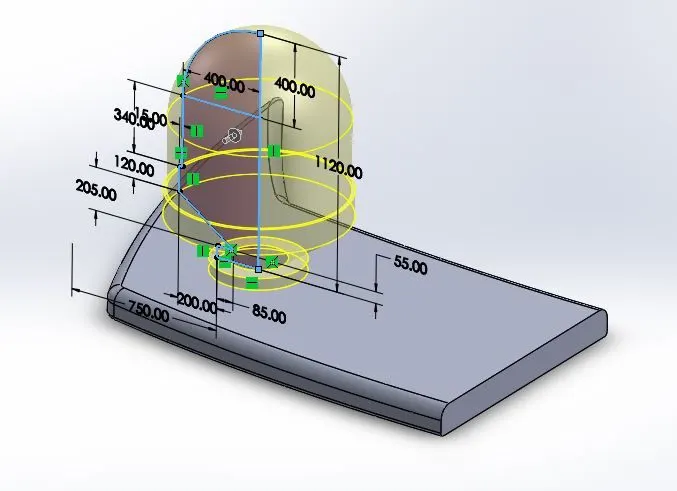
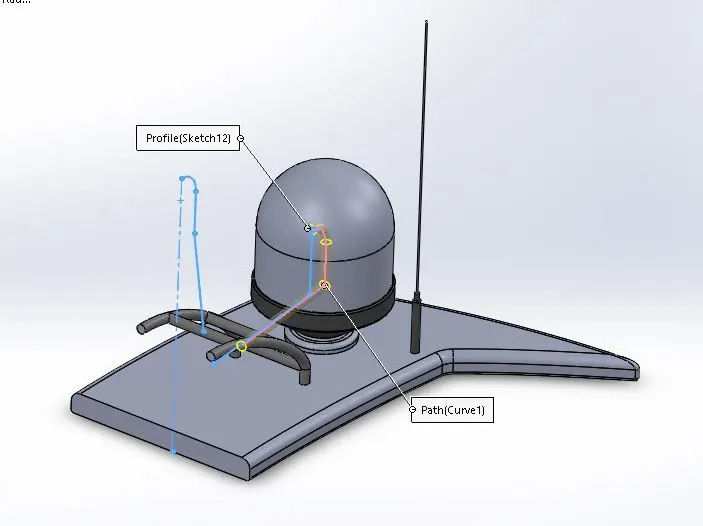
- Features like boss extrude, cut extrude, revolve boss, swept boss, and projected curve are used to model radar mast.
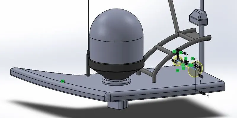
- Projected curves are used to create pipe bodies using the swept boss feature. The Dome feature is used to form curvature on the horn surface.
- Shell feature is used to get a hollow horn body.
- Chamfers and fillets are provided at the required edges
- Paste the yacht blueprints onto the new part.
- Create the bottom plate of the radar and fillet the sharp edges.
- Create a cylindrical tank on the bottom plate.
- Fillet and chamfer the required edges.
- Create the antenna starting from the bottom plate. Create a radar holder and a light holder.
- Create two horns on the bottom plate of the radar mast.
- Create the remaining parts of the radar mast by mirroring the modeled parts up to the last step.
- Apply the appropriate paint to all required surfaces.
Feature Manager Design Tree: -
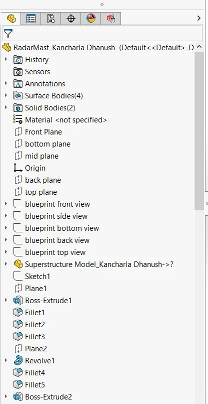
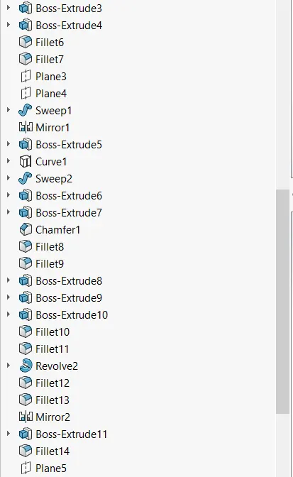
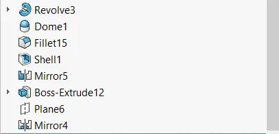
-
Step 3 - Presentations
3. All Views of the Gas Tank: -
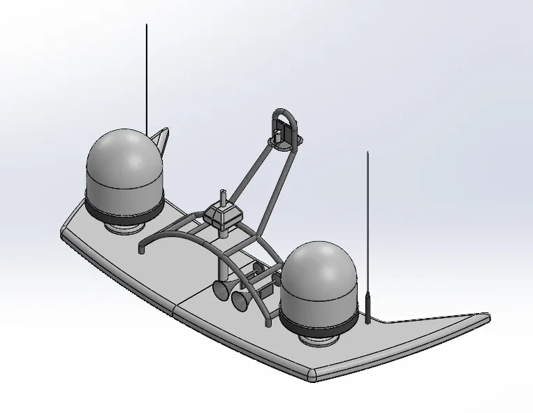
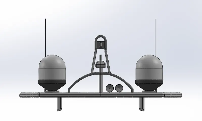
ISOMETRIC VIEW FRONT VIEW
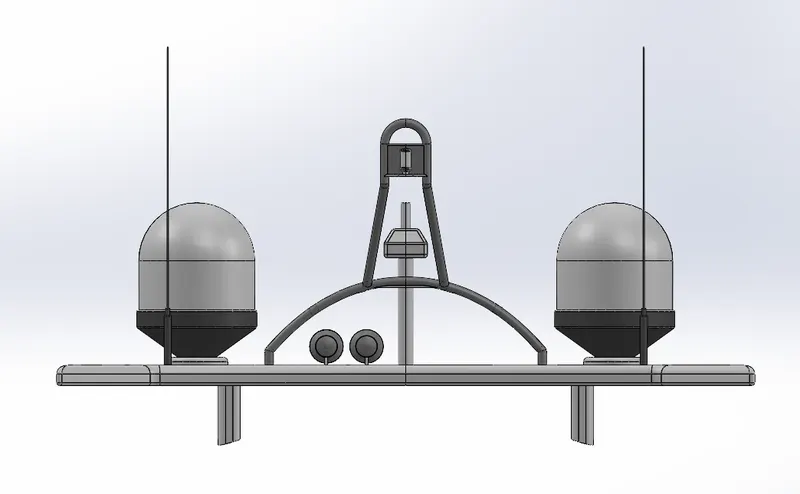
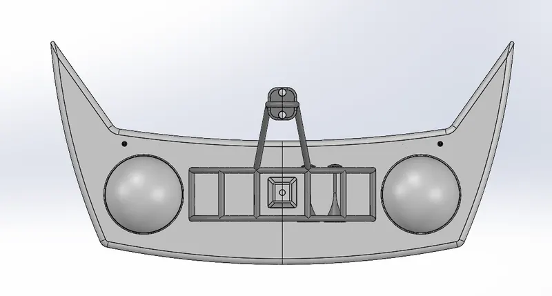
BACK VIEW TOP VIEW
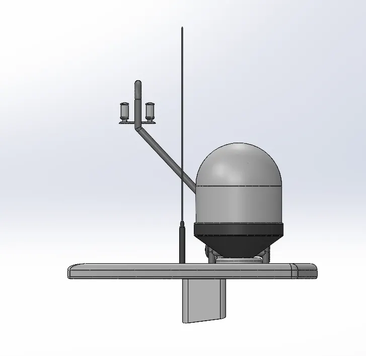
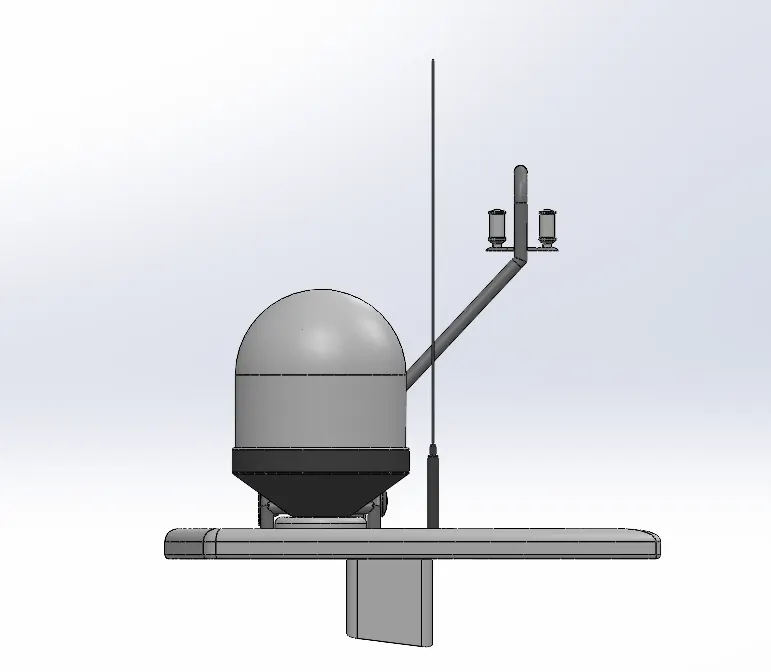
LEFT VIEW RIGHT VIEW
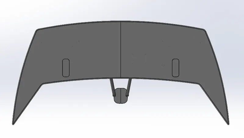
BOTTOM VIEW
******************************************************************************************
Part Link of Entire Assembly of Yacht: -
- https://drive.google.com/file/d/1pGO2s8CxO5g2lW6uuSLosIBH1FTlzXaI/view?usp=sharing
Assembly Of Yacht-
The main purpose of the assembly of the Yacht is that assembly all individual parts with suitable mates.
Procedure: -
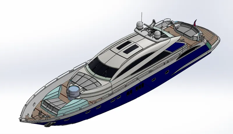
Isometric View
The following procedure is used to create an Assembly of Yacht: -
- Open SolidWorks and all the Yacht's components.
- Now choose the new file, then open the assembly. Next, click the insert option, choose the chassis, and then click OK.
- Finally, click the insert option once again and choose Hull.
- Select the front plane of the engine and the front plane of the assembly, and then expand the engine menu bar.
- Choose the engine stand to face and the chassis face, then align them.
- Choose the engine's and the chassis' bottom front face, then provide measurements.
- Insert the pedal now, then make the pedals extrude and the stand's holes concentric by selecting them, as well as the pedal's right face and the stand's left face by coincidence.
- The sketch was altered because of the exhaust interfering with the pedal's opening of the engine portion. Then save the file; there will now be no interference when you access the assembly.
- Select the mirror option, mirror the pedal using a linear component pattern, and follow the on-screen instructions.
- Install the kickstand, then choose the top face of the stand's extrude on the chassis and the inside of the top face of the stand, making sure they are coincident.
- You can also choose the hole on the chassis and the stand's circular extrude, making sure they are concentric, and choose the midplane of the stand and the left face of the chassis, making sure they are compatible.
- The transmission belt should now be inserted, with its larger inside face aligned with the engine's larger pulley.
- Select the mate option, increase the mate width, then choose the transmission belt's side sides and the pulleys inside faces.
- Change the belt's dimension to 61.5mm diameter as the smaller end of the transmission, choose the top face of the belt and the face of the engine, and make a 7-degree angle.
- Insert the oil tank now, aligning the bottom edge of the oil tank with the fillet edge of the engine back, and then choose the bottom face of the oil tank and the top of the engine back.
- Choose the midpoints of the oil tank and the chassis, then align them.
- Then, insert the rear wheel and rotate it three times in the Y-direction, choosing the wheel's hole and the chassis' shaft to be concentric, choosing the right plane of the rear wheel and the chassis' midplane to be concentric, and choosing the right plane of the chassis and the front plane of the rear wheel to be parallel.
- To make the round edge of the rear fender and any circle on the rear wheel concentric, pick insert, click on the rear fender, and rotate it once in the Z direction and three times in the Y direction.
- Pick the vertical fender plane and the right plane of the chassis and make them parallel. Finally, select the midplane of the fender and the midplane of the chassis.
- Choose the chain and chassis, then isolate them. Sketch on the back face of the chain, then split it to remove chain interference, and fillet with 3mm.
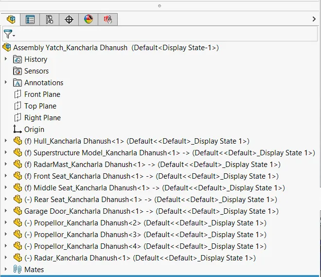
Feature Manager Design Tree: -
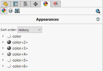
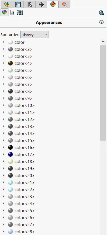
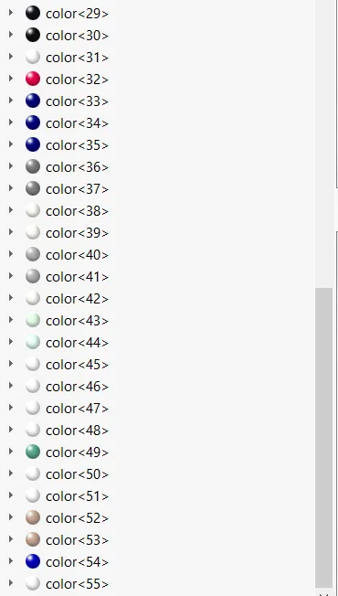
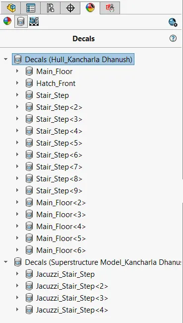
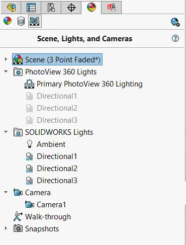
Feature Manager Design Tree of Appearances: -
All Views of the Assembled Yacht: -
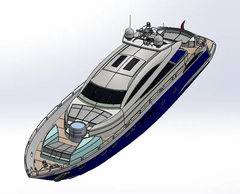
ISOMETRIC VIEW TRIMETRIC VIEW
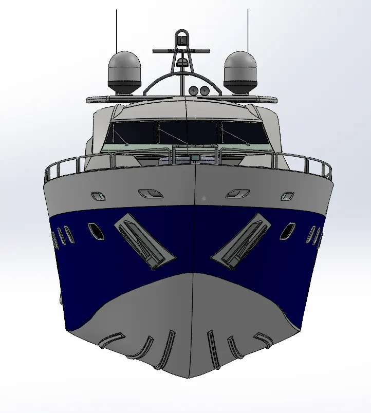
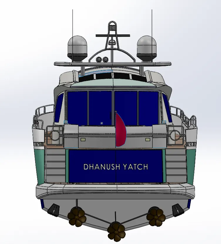
FRONT VIEW BACK VIEW
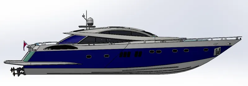
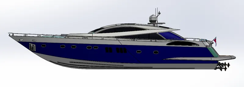
LEFT VIEW RIGHT VIEW
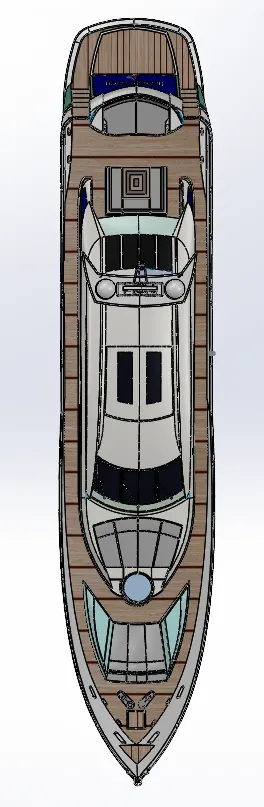
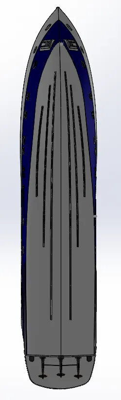
TOP VIEW BOTTOM VIEW
******************************************************************************************
Zip File of All the Parts of Yacht: -
Link: - https://drive.google.com/file/d/1ezaU0KqsJOn6KtyA0yQqtuYWpcrCcPao/view?usp=sharing
MODELLING AND RENDERING OF A YACHT
Objective: -
-
The main goal is to construct various boat components using appropriate solid/surface modeling elements that will expedite the design process.
-
Recognizing the value of a detailed sketch enables us to change the proportions without error at any time.
recognizing the yacht's construction process. -
Experimenting with various appearances, sceneries, rendering parameters, etc. to produce high-quality rendered photos on SolidWorks photoview360 and SolidWorks visualize.
Introduction: -
-
A yacht is a type of boat used for recreation or competition.
-
Most modern yachts are used for leisure.
-
Any sailor power-powered watercraft used for racing, cruising, or leisure is a yacht.
-
All yachts were made of steel or wood up until the 1950s, but today a far wider variety of materials are used.
-
Although wood hulls are still made, fiberglass is the most often used building material, followed by steel, aluminum, carbon fiber, and cement.
-
The best weight-to-strength ratios among all boatbuilding materials are found in spruce veneers laminated with epoxy resins, which are superior to materials like carbon fiber and aramid fiber.
-
These yachts have developed in recent years from basic boats with minimal accommodations to sophisticated and opulent craft.
- Increased automation and "production line" techniques for yacht construction, as well as lower hull-building costs brought on using fiberglass hulls, are to blame for this. Most simple yachts include radios, electric illumination, and GPS navigational aids. Many tools are used, including radar, echo-sounding, and autopilot.
Design Methodology: -
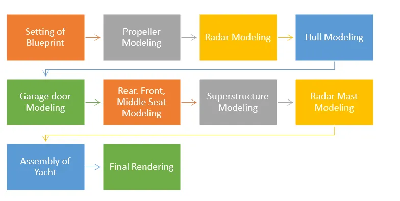
Description: -
When modeling a part, the 2D sketch is created first using the tools in the sketch tab, and the 2D sketch is then turned into a 3D part utilizing features in the features tab.
FEATURES: -
-
Boss Extrude: This function enlarges the item in three dimensions following the drawing plane.
-
Extrude Cut: This ability is used to cut or remove a 3D object in a straight line following a drawing.
-
Fillet: A feature used to create smooth, rounded internal or external edges to prevent sharp edges.
-
Lofted Boss/Base: The lofted boss is a characteristic that is utilized to create Complex Shapes. It accomplishes this by interpolating surfaces between different model cross-sections. Sketches, faces, or edges can be included in these cross-sections.
-
Split: The split tool is used to divide a single solid part into two solid pieces. It is used to project an object onto curved or planar surfaces.
-
Dome: A dome-shaped extrusion, such as an elliptical dome, can be made with this feature.
-
Shell: The shell feature is used to create a hollow space in a solid part by choosing the solid part's exterior wall and subsequently removing the inside portions. Additionally, it is applied to lessen a particular thickness.
-
Combine: The combined tool is used to integrate two solid elements that cross each other and form a single solid part.
-
Chamfer: The term "chamfer" refers to the process of making a sharp edge or corner tapered rather than perfectly square.
-
Linear Pattern: The pattern is created using a different number of instances than what is needed to do so.
-
Curve-Driven Pattern: A curve-driven pattern follows a previously designed curve to create any pattern.
-
Circular pattern: A feature that converts 3D features into circular patterns based on the number of insistences is known as a circular pattern.
-
Revolve boss base: The revolve function is utilized to create a 3D extrusion that is cylindrical or circular along with a specified reference axis according to a sketched design.
-
Revolve cut: Revolve cut is used to remove or lessen the extrusion of cylindrical spherical surfaces.
-
Copy/move the 3D body: This function allows you to move or copy the 3D body between two locations.
-
Mirror: By using the reference of the chosen plane, the mirror is used to reflect a feature or body.
-
Sweep: You can use this function to sweep any completely developed sketch alongside the path.
-
Sweep cut: Also known as a sweep feature, sweep cut performs a cut along the sweep path and is directly proportional to sweep.
-
Swept Surface: This technique creates a surface parallel to the path along which the curve is driven.
-
Boundary Surface: A surface between two finished surfaces is created using a boundary surface.
-
Loft Surface: A loft surface is used, together with a guide path, to create a loft between two profiles.
-
Knit surface: A knit surface lowers the space between two surfaces' edges and is used to knit their two free or open edges together.
-
Surface Trim: It has two modes: Standard and Mutual and are mostly used to remove material from a surface.
-
Projection Curve: A projection curve is a three-dimensional curve that is created by projecting two different two-dimensional curves onto two different planes.
-
Blocks: You can create, save, edit, and insert blocks from the sketch entities and drawing elements you frequently use, such as standard notes, title blocks, label positions, and so forth. You can also attach blocks to geometry or drawing views.
-
Trim entities: This tool is used to cut any extraneous lines or entities from a sketch.
-
Appearances: A model's appearance describes its outward characteristics, such as color and texture. Physical qualities, which are determined by materials, are unaffected by appearances. Every substance has a default appearance.
ASSEMBLY: -
- Putting parts together on an assembly line is the most common definition of assembly, but it can also refer to generating a finished product that fulfills its intended purpose.
- When a component is changed, the assembly is automatically updated, i.e. Rebuilding the document will either happen automatically or prompt the user to do so.
MODELING OF Yacht: -
This model has nine individual parts which are:
- Propeller,
- Radar,
- Blueprint Setup,
- Hull,
- Garage door,
- Front seat,
- Middle seat,
- Rear seat,
- Superstructure,
- Radar mast.
Component 1: -
Propeller -
1. The following Propeller has been created according to the given dimensions.
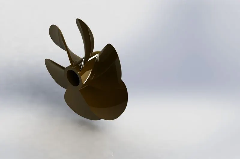
Rendered Image
2. Modeling of the Propeller
- A propeller is a device with a rotating hub and radiating blades arranged helically in shape.
- Archimedes' screw performs a similar function to this spiral.
- By acting on a working fluid, such as water or air, it converts rotational power into linear thrust.
Step 1 - Features
- Using revolve, 2D sketches can be rotated about a central axis.
- The 2D closed sketch can be rotated about a central axis using the revolve command.
- Extruded items are cut using a process called cut extrude. This functionality is utilized in this component to create a hole above the revolved section.
- Loft: a material used to make a propeller's vanes.
- A circular pattern is used to duplicate a pattern in a circle.
- To give all the edges a rounded appearance, apply a fillet.
Step 2- Drawing
- Open SolidWorks
Go to: Start > Programs > SolidWorks SW - Create a new part
Open a new part with model units set to millimeters.
Go to: File > New > Part - Select the three planes in the feature tree (hold down the Control key) and make them visible by clicking on the glasses.
- Create a new sketch on the Right Plane.
- Select the Right Plane in the Feature Manager.
- Click on the 2D Sketch icon to make a new sketch.
- Click on the Normal To option to rotate and zoom the model to normal to the selected Plane.
- Draw the three straight lines as shown in the picture. The 350mm line should be placed on the middle axis of the Right Plane.
- Draw the spline.
- Add a tangency relation to the transition between the horizontal line and the spline.
- Select the horizontal line, hold down the Control key and select the spline.
- Click on the Tangency icon
- in the Add Relations bar to add a tangency relation between the line and the spline.
- Create a Revolve -> Go to Insert > Boss / Base > Revolve or click on the revolve icon, Axis of revolution: Select the blue line.
- Create a new sketch on the Top Plane and select the Top Plane in the Feature Manager. Click on the 2D Sketch icon to make a new sketch.
- Click on the Normal To option to rotate and zoom the model normal to the selected Plane.
- Create a 3-Point Corner Rectangle -> Go to Tools > Sketch Entities > 3 Point Corner Rectangle or click on the 3-Point Corner Rectangle icon.
- Draw the rectangle, change the dimensions of the rectangle, and close the sketch.
- Create a New Plane -> Go to Insert > Reference Geometry > Plane or click on the New Plane icon.
- First Reference: Select the Top Plane.
- Change the Offset Distance to 360 mm.
- Create a new sketch on the new Plane 1 and select the new Plane1 in the Feature Manager.
- Click on the 2D Sketch icon to make a new sketch and click on the Normal To option to rotate and zoom the model
normal to the selected Plane. - Draw the 3-Point Corner Rectangle. Go to Tools > Sketch Entities > 3 Point Corner Rectangle or click on the 3 Point Corner Rectangle icon.
- Draw the rectangle, change the dimensions of the rectangle, and close the sketch.
- Create a Solid Loft -> Go to Insert > Boss / Base > Loft or click on the Loft icon.
- Click in the Profiles box and select Sketch2 and Sketch3.
- Make sure that the green balls are both in the same rectangular corner with blue circle details.
- If not, click and drag one ball to another corner of the rectangle and click OK.
- Create two Fillets on the edges of the loft -> Go to Insert > Features > Fillet / Round or click on the Fillet icon.
- Select the two edges. Select Full preview for a preview of the fillet.
- Change the Radius to 135 mm and click OK.
- Create a fillet on the edge of the blade -> Go to Insert > Features > Fillet / Round or click on the fillet icon.
- Select the front edge of the loft, change the Radius to 30 mm, and Click OK.
- Create a fillet on the edge of the axle and blade Go to Insert > Features > Fillet / Round or click on the fillet icon.
- Select the two edges, change the Radius to 10mm, and Click OK.
- Create a Circular Pattern ->Go to Insert > Pattern / Mirror > Circular Pattern or click on the Circular Pattern icon.
- Pattern Axis: Select the blue surface. Total Angle: 360 deg.
- The number of instances Selects the " Equal Spacing " option.
- Features to Pattern: Loft1, Fillet1, Fillet2, Fillet3.
- Select the " Geometry Pattern " option and select the " Propagate Visual Properties " option and Click OK.
-
Step 3 - Presentations
- Change the color of the propeller: Click on the Propeller model.
- Click on the appearances button.
- Click on the Body option.
- Change the color to a custom brown by changing the RGB numbers to 71, 45, and 0 and Clicking OK.
Component 2: -
Radar -
1. The following Radar has been created according to the given dimensions.
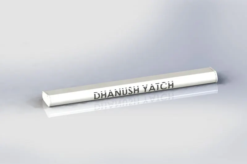
Rendered Image
2. Modeling of the Radar
- Radar is a detection device that makes use of radio waves to decide the range, angle, or speed of objects.
- It may be used to hit aircraft, ships, spacecraft, guided missiles, motor vehicles, climate statistics, and terrain.
- A radar device includes a transmitter generating electromagnetic waves inside the radio or microwave domain, a transmitting antenna, a receiving antenna (frequently the same antenna is used for transmitting and receiving), and a receiver and processor to decide the homes of the objects).
- Radio waves (pulsed or continuous) from the transmitter mirror the item and go back to the receiver, giving statistics about the item's vicinity and speed.
Step 1 - Features
- Bosses extrude - used to extrude the closed 2D sketch up to desired height.
- Cut extrude – used to cut the extruded part to make a hole or cut the undesirable part.
- Fillet – used to give the rounded shape to the corners & edges with a required radius.
- Sketch pattern – used to pattern features over a sketched point.
- Mirror – used to mirror the body by giving the mirror face as a reference.
- Spit line – used to cut the face into parts. In radar, this feature is used to print the text over it.
- Text – it is a 3D text to be printed over the radar, using split line command.
Step 2- Drawing
- Insert the blueprint of the yacht in a new part.
- Create the side view of the radar and extrude it.
- Provide fillet to all the sharp edges.
- Create a cap and fasteners on the side of the radar.
- Create the remaining part of the radar by mirroring the hull modeled till the last step.
- Apply decals and appearance on the surface of the radar.
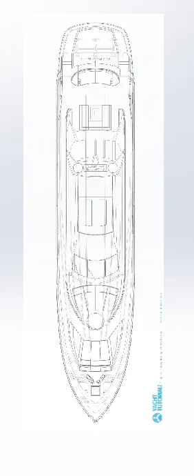
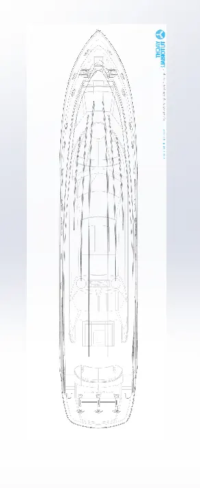
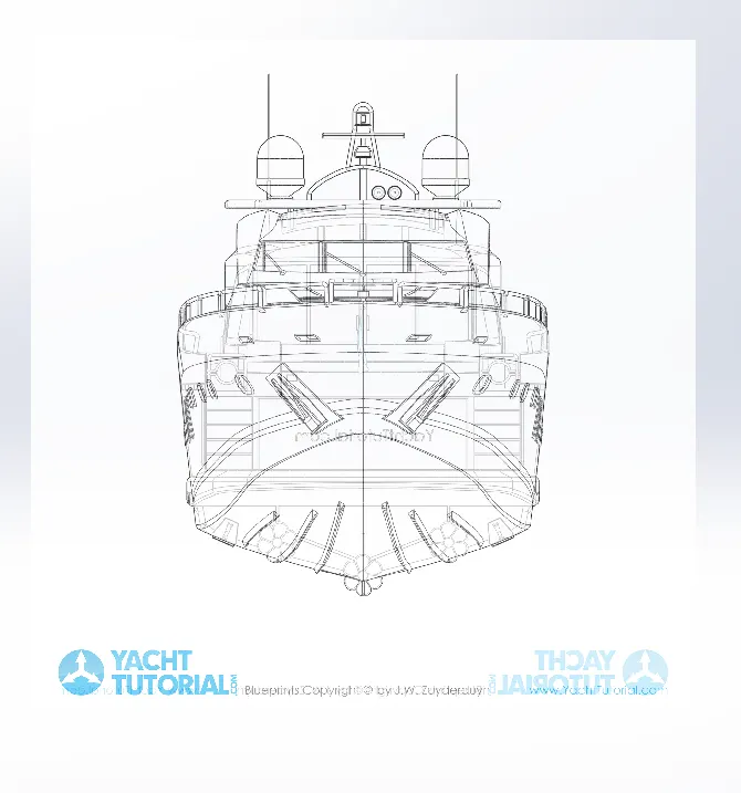
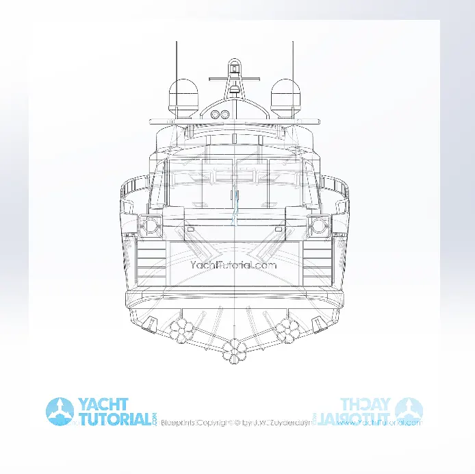
3) Blueprint Setup -
BLUEPRINT
- A blueprint is a guide for making something or it's a design or pattern that can be
followed by further guidance while designing individual parts of the yacht. - Blueprint is a combination of multiple images of the yacht, such as front
view, top view, side view, bottom view, and back view.
Procedure and features used in a blueprint.
- Open a new part and create a blueprint of the yacht.
- In a new sketch, import the image of the top view of the yacht and place it at an appropriate
position with respect to the origin. - Repeat the previous step to all the views such as Front view, Side view, Bottom view, and Back
view. - Save the file as the blueprint of the yacht.
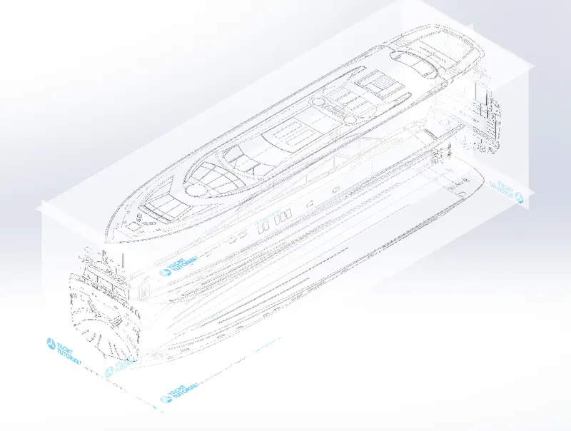
ISOMETRIC VIEW
TOP VIEW BOTTOM VIEW
FRONT VIEW BACK VIEW
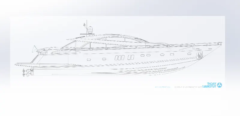
LEFT VIEW
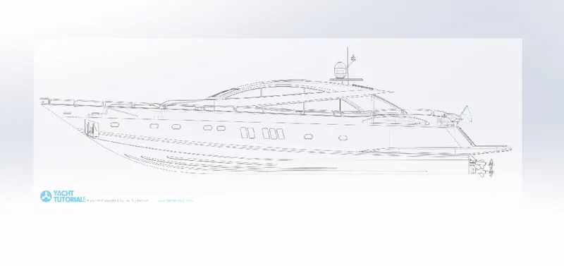
RIGHT VIEW
Component 4: -
Hull -
1. The following Hull has been created according to the given dimensions.
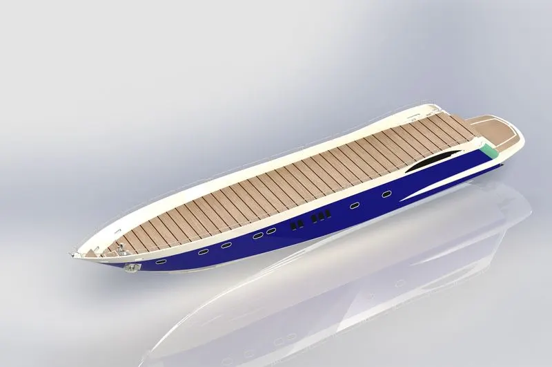
Rendered Image
2. Modeling of the Hull
- The hull is a basic, symmetrical model of a yacht.
- Therefore, it is enough to model one half, and the other half can be mirrored.
- First, develop the hull in surface modeling, complete the model through surfaces, then convert the model to a solid and proceed to solid modeling.
- This is because the hull consists of surfaces with complex curvatures. So, it's a clever idea to model the surface and then convert it to a solid.
Step 1 - Features
- 3D sketch,
- Loft Surface,
- Sweep Surface,
- Trim Surface,
- Ruled Surface,
- Boundary Surface,
- Surface Extrude,
- Knit Surface,
- Reference Plane,
- Fill the Surface,
- Sweep,
- Extrude,
- Cut Extrude (offset from the surface),
- Revolve, Shell, Fillet,
- Chamfer,
- Split (with the consumed cut body and the removed body saved as a different part in the name of the garage door).
Component 5: -
Garage Door -
1. The following Garage Door has been created according to the given dimensions.
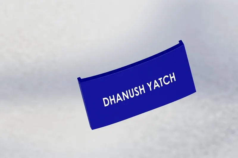
Rendered Image
2. Modeling of the Garage Door
- This Garage Door is modeled in the solid model that was saved using the Split command while modeling the hull.
- Parts are salvaged and used to build garage doors. It's a symmetrical model, so the other half is a mirror image.
- The name is imprinted using text and the cut (offset from the surface) extrude command.
Step 1 - Features
- cut extrude,
- extrude,
- fillet,
- chamfer and mirror.
- Insert the blueprint of the yacht in a new part.
- Insert a block from the hull, which is removed from the hull for creating a garage for parking of a
private vehicle in the hull. - Remove all the unwanted portions of the block inserted and provide a fillet on all the required edges.
- Create the remaining part of the garage door by mirroring the garage door modeled till the last
step. - Create the name of the yacht on the surface of the garage door.
- Apply color to the surface of the door.
Component 6: -
Front Seat -
1. The following Front Seat has been created according to the given dimensions.
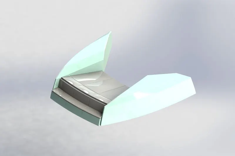
Rendered Image
2. Modeling of the Front Seat
- The front seats are at the front of the hull and have a nice, cushioned seating area typically used on yachts.
Step 1 - Features
- 3D sketch.
- Paste the yacht blueprints onto the new part.
- Use the bottom of the hull to create protrusions on the sides of the front seats of the yacht surface modeling.
- Create a seating area for the front seats.
- Fillet and chamfer the required edges.
- Creates additional cushion on the surface of the seat. Fillet and chamfer the required edges.
- Create the rest of the front seat by mirroring the seat modeled up to the last step.
- Apply the appropriate paint to all required surfaces.
Component 7: -
Middle Seat -
1. The following Middle Seat has been created according to the given dimensions.
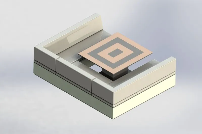
Rendered Image
2. Modeling of the Middle Seat
- The middle seat is just behind the superstructure.
- The middle seat consists of a table and chairs.
Step 1 - Features
- Paste the yacht blueprints onto the new part.
- Make the base of the middle seat.
- Create a seating area above the base of the seat.
- Create a sheet upholstery part on top of a sheet part.
- Fillet and chamfer the required edges. Create the rest of the center seat by mirroring the modeled seat up to the last step.
- Make a table in the middle of the middle seat.
- Apply paint to all necessary surfaces.
Component 8: -
Rear Seat -
1. The following Rear Seat has been created according to the given dimensions.
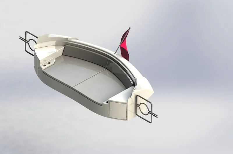
Rendered Image
2. Modeling of the Rear Seat
- The rear seat is kept at the rear end of the hull.
- The rear seat has a wooden cupboard and teacup holder as an additional feature.
Step 1 - Features
- Paste the yacht blueprints onto the new part.
- Use surface modeling to create the back of the yacht's rear seats on the bottom of the hull.
- Build a rear-seat basement.
- Fillet and chamfer the required edges.
- Create a palm rest on the side of the rear seat. Make a drink holder next to the palm rest.
- Creates additional cushion on the surface of the seat.
- Fillet and chamfer the required edges.
- Create a dice board under the palm rest part.
- Make a gate on one side of the back seat. Create the rest of the rear seats by mirroring the seats modeled up to the last step.
- Create a flag holder and flag on the back of the back seat.
- Apply the appropriate paint to all required surfaces.
Component 9: -
Super Structure -
1. The following Super Structure has been created according to the given dimensions.
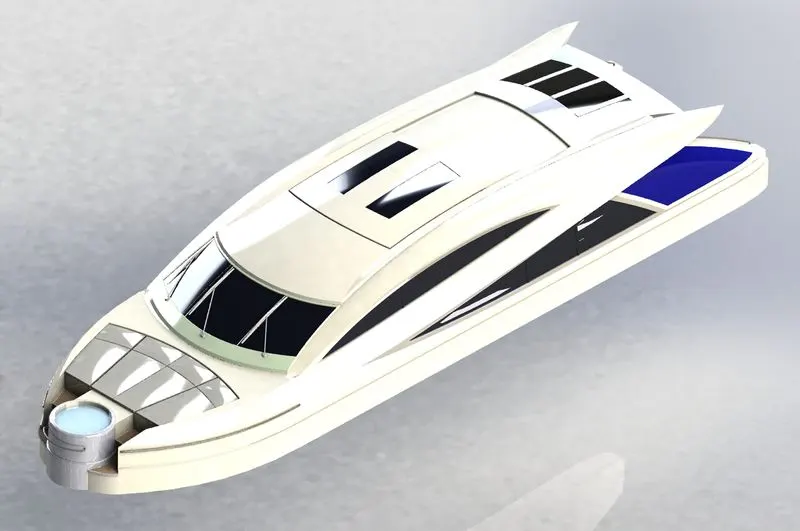
Rendered Image
2. Modeling of the Super Structure
- A superstructure is an upward extension of an existing structure above a baseline.
- The superstructure is a yacht is a part that emerges from the deck.
- Space for living accommodation, meeting room, etc.
Step 1 - Features
- Paste the yacht blueprints onto the new part.
- Create half of the superstructure in surface modeling and convert it to a solid.
- Place the foundation container on the front of the main unit.
- Provide a handle on the surface of the foundation container.
- Create a step at the front of your setup. Create a glass window section on the surface of the building.
- Create a wiper part at the top of the front window.
- Create the handle for the rear door of the superstructure.
- Create a surface on top of the foundation container and give it the proper transparency.
- Apply paint to all necessary surfaces.
- The superstructure is an upward extension of an existing structure above the baseline.
- It consists of the part that protrudes from the main deck of a ship or yacht (in this case).
- The size of a watercraft structure can have many effects on its performance as the structure's stiffness, displacement, and/or stability differ.
- It surrounds the yacht's cabin and living area.
- They are designed to provide added value and minimize obstacles to speed and mobility.
- Designed by importing the hull deck surface as an interface surface.
- The design required precise curvature during the sketching stage to avoid showing incorrect geometry during the modeling stage.
- This means adding structures to existing structures. On ships, this is the designation of the part of the ship that emerges from the deck.
Component 10: -
Radar Mast -
1. The Radar Mast has been created according to the dimensions.
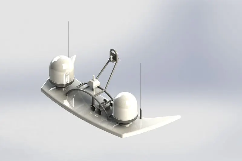
Rendered Image
2. Modeling of Radar Mast -
- Radar masts contain radar, antennas, satellite domes, and lights.
- The upper surface of the superstructure was designed as an interfacial surface.
- A radar mast is a yacht component that contains the vital electronics that connect to the radar and provide the signal it receives via the antenna and includes horns and lights.
- The radar mast is the mounting device of the radar in the ship.
- It has an appropriate position for keeping all the radar-related equipment such as a transmitter, receiver, processor, etc.
- The radar mast is assembled on top of the superstructure on which the radar is fitted.
- It contains a receiver/antenna which collects the signal and triggers the radar to move.
Step 1 - Features
- Sketch,
- Extrude,
- Revolve,
- Sweep,
- Dome,
- Shell,
- Cut Extrude,
- Chamfer,
- Fillet.
Step 2- Drawing
- First, import the surface body created in the superstructure which will be used as a reference.
- Features like boss extrude, cut extrude, revolve boss, swept boss, and projected curve are used to model radar mast.
- Projected curves are used to create pipe bodies using the swept boss feature. The Dome feature is used to form curvature on the horn surface.
- Shell feature is used to get a hollow horn body.
- Chamfers and fillets are provided at the required edges
- Paste the yacht blueprints onto the new part.
- Create the bottom plate of the radar and fillet the sharp edges.
- Create a cylindrical tank on the bottom plate.
- Fillet and chamfer the required edges.
- Create the antenna starting from the bottom plate. Create a radar holder and a light holder.
- Create two horns on the bottom plate of the radar mast.
- Create the remaining parts of the radar mast by mirroring the modeled parts up to the last step.
- Apply the appropriate paint to all required surfaces.
Assembly Of Yacht-
The main purpose of the assembly of the Yacht is that assembly all individual parts with suitable mates.
Procedure: -
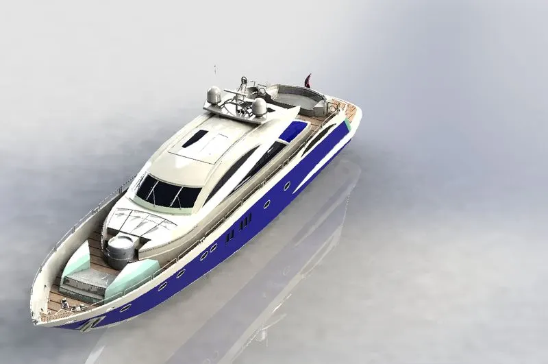
Rendered Image of Timetric View
The following procedure is used to create an Assembly of Yacht: -
- Open SolidWorks and all the Yacht's components.
- Now choose the new file, then open the assembly. Next, click the insert option, choose the chassis, and then click OK.
- Finally, click the insert option once again and choose Hull.
- First, open the Solid works File then click Insert > Component > Existing part/Assembly.
- Then click the browse button then select hull It automatically fixes it then one by one open the part assembly is automatic. Then propeller relates to the hull using the concentric command and coincidence command.
- The rear seat is Select the Mid Plane of the Hull and the Right Plane the feature
tree as entities to mate.
Rendered Images of All Views of the Assembled Yacht: -
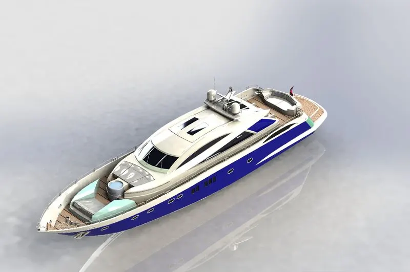
ISOMETRIC VIEW TRIMETRIC VIEW
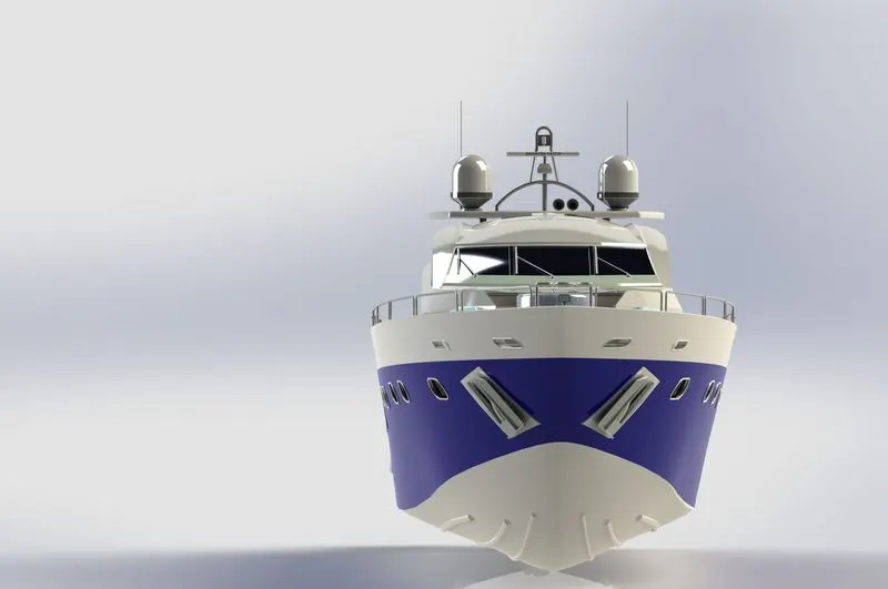
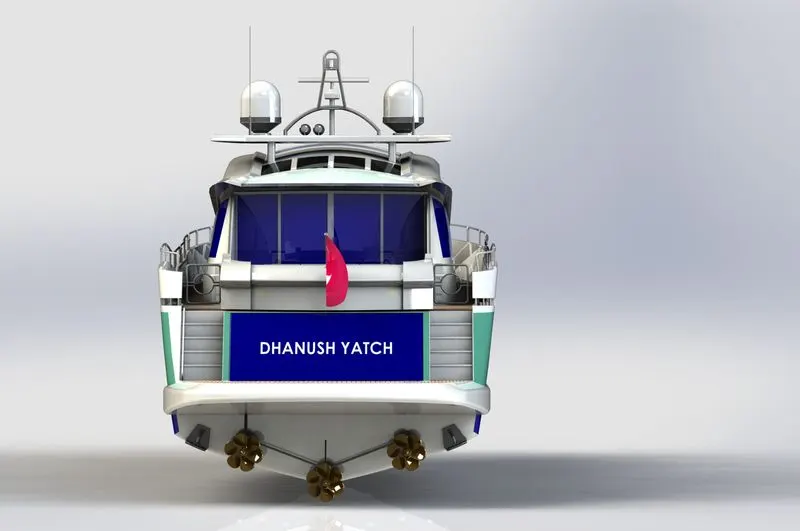
FRONT VIEW BACK VIEW
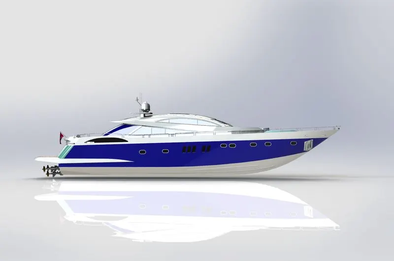
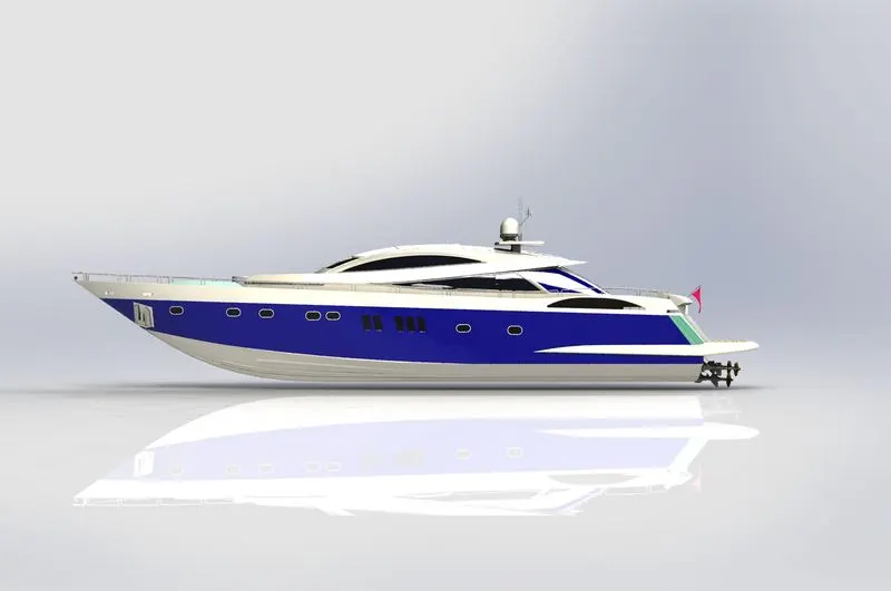
LEFT VIEW RIGHT VIEW
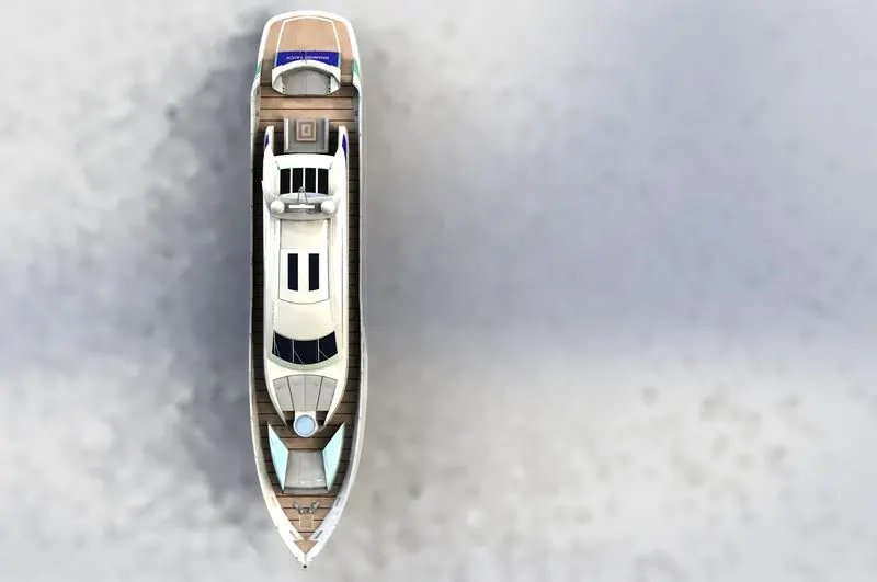
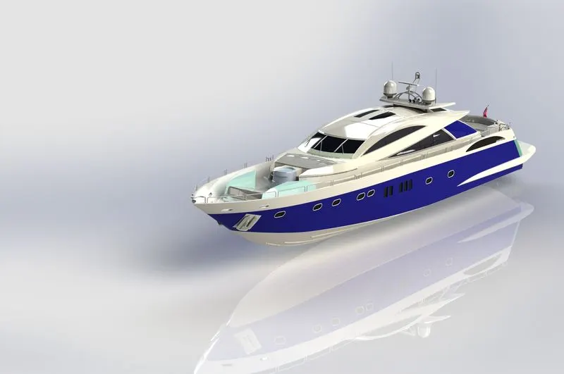
TOP VIEW CAMERA 1 VIEW
Explanation of each component: -
The mates' feature is used to assemble the American chopper. Each component has a defined relationship with either the base component or the other components. The following are some relationships that are utilized to couple the components of an American helicopter:
- Concentric
- Coincident
- Parallel
- Tangent
- Width
DECAL APPLICATION, CAMERA SET-UP, & SCENES: -
The oil tank, gas tank, and rear fender all have decals on them. For adding the decals, we can use projected and label in the mapping process.
The view tab is where the camera is added; the view tab also contains the light. Final rendering is helped by camera setup.
Sceneries: Appropriate scenes are added to the model to increase realism.
RENDERING: -
We used the Solid works Visualization tool to depict the helicopter. We used render tools in Solid works to render individual pieces.
Procedure: -
- Visualize by importing the assembly model.
- Modify the model's appearance however you like.
- The model should have scenes.
- The final rendering is completed when finished.
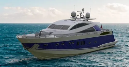
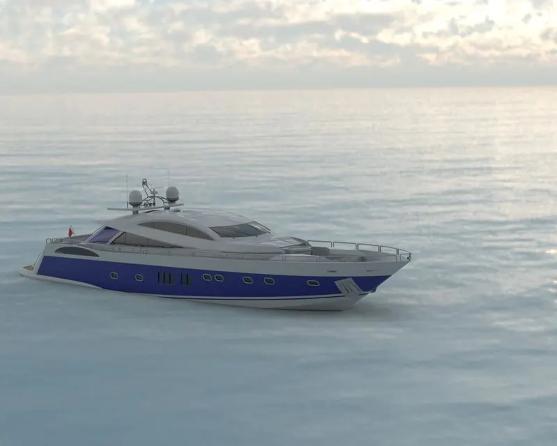
FINAL RENDERS OF THE YACHT: -
CONCLUSION: -
The project on designing a Yacht with the photorealistic depiction in Solid works was designed and completed. As a result, SOLIDWORKS is used to design and construct the parts of the YACHT, and PHOTO VIEW 360 and SOLIDWORKS VISUALIZE are used to transform the parts into photorealistic images.