Photo Realistic Rendering
PHOTO-REALISTIC RENDERING USING SOLIDWORKS FOR THE DESIGN OF THE AMERICAN CHOPPER & ITS COMPONENTS
Objective: -
An American Chopper will be modeled using the CAD (computer-aided drafting) program (SOLIDWORKS) and will then be rendered using SOLIDWORKS Visualize to produce a photorealistic representation of the vehicle. from the first conception of an American chopper to the model's final representation. Working on a physical model for this assignment aids in better understanding the tools in Solid works.
Introduction: -
American choppers are unique motorcycles that draw attention to the concept alone. These bikes were advertised by customers at trade exhibitions or sold at auctions to generate money for charity. In this project, we assembled a model of an American chopper using Solid works after building each part. I've always wanted to create a full vehicle on my own as an automobile design engineer, and with this project, it came true.
This project demonstrates how to create an American motorcycle using the CAD program SOLIDWORKS, from sketching and modeling the individual components to the final rendering of the assembled motorcycle to provide a photo-realistic view.
Design Methodology: -
- Part Modeling
- Assigning Appearances to each part
- Assembly of Parts
- Assigning Decals, Lighting, and Camera
- Rendering.
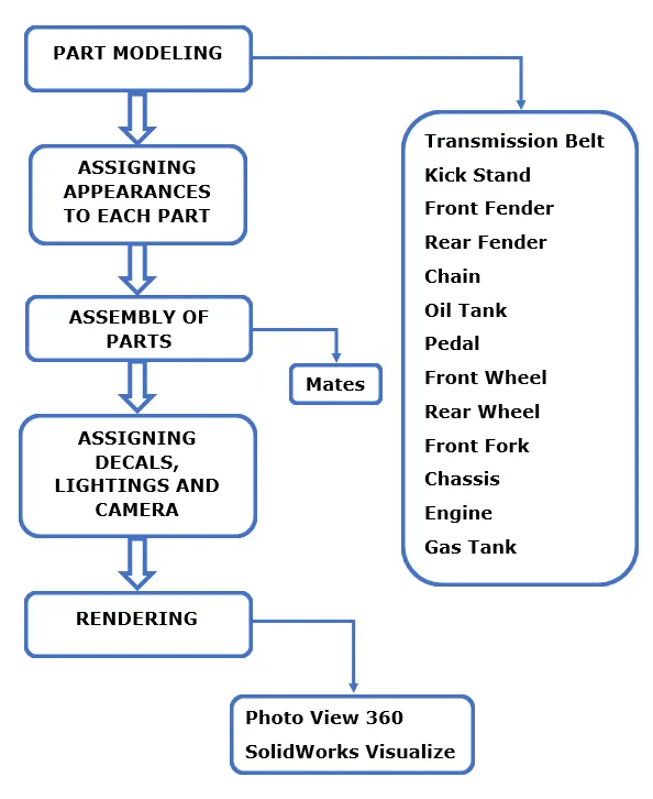
Description: -
When modeling a part, the 2D sketch is created first using the tools in the sketch tab, and the 2D sketch is then turned into a 3D part utilizing features in the features tab.
FEATURES: -
-
Boss Extrude: This function enlarges the item in three dimensions following the drawing plane.
-
Extrude Cut: This ability is used to cut or remove a 3D object in a straight line following a drawing.
-
Fillet: A feature used to create smooth, rounded internal or external edges to prevent sharp edges.
-
Lofted Boss/Base: The lofted boss is a characteristic that is utilized to create Complex Shapes. It accomplishes this by interpolating surfaces between different model cross-sections. Sketches, faces, or edges can be included in these cross-sections.
-
Split: The split tool is used to divide a single solid part into two solid pieces. It is used to project an object onto curved or planar surfaces.
-
Dome: A dome-shaped extrusion, such as an elliptical dome, can be made with this feature.
-
Shell: The shell feature is used to create a hollow space in a solid part by choosing the solid part's exterior wall and subsequently removing the inside portions. Additionally, it is applied to lessen a particular thickness.
-
Combine: The combined tool is used to integrate two solid elements that cross each other and form a single solid part.
-
Chamfer: The term "chamfer" refers to the process of making a sharp edge or corner tapered rather than perfectly square.
-
Linear Pattern: The pattern is created using a different number of instances than what is needed to do so.
-
Curve-Driven Pattern: A curve-driven pattern follows a previously designed curve to create any pattern.
-
Circular pattern: A feature that converts 3D features into circular patterns based on the number of insistences is known as a circular pattern.
-
Revolve boss base: The revolve function is utilized to create a 3D extrusion that is cylindrical or circular along with a specified reference axis according to a sketched design.
-
Revolve cut: Revolve cut is used to remove or lessen the extrusion of cylindrical spherical surfaces.
-
Copy/move the 3D body: This function allows you to move or copy the 3D body between two locations.
-
Mirror: By using the reference of the chosen plane, the mirror is used to reflect a feature or body.
-
Sweep: You can use this function to sweep any completely developed sketch alongside the path.
-
Sweep cut: Also known as a sweep feature, sweep cut performs a cut along the sweep path and is directly proportional to sweep.
-
Swept Surface: This technique creates a surface parallel to the path along which the curve is driven.
-
Boundary Surface: A surface between two finished surfaces is created using a boundary surface.
-
Loft Surface: A loft surface is used, together with a guide path, to create a loft between two profiles.
-
Knit surface: A knit surface lowers the space between two surfaces' edges and is used to knit their two free or open edges together.
-
Surface Trim: It has two modes: Standard and Mutual and are mostly used to remove material from a surface.
-
Projection Curve: A projection curve is a three-dimensional curve that is created by projecting two different two-dimensional curves onto two different planes.
-
Blocks: You can create, save, edit, and insert blocks from the sketch entities and drawing elements you frequently use, such as standard notes, title blocks, label positions, and so forth. You can also attach blocks to geometry or drawing views.
-
Trim entities: This tool is used to cut any extraneous lines or entities from a sketch.
-
Appearances: A model's appearance describes its outward characteristics, such as color and texture. Physical qualities, which are determined by materials, are unaffected by appearances. Every substance has a default appearance.
ASSEMBLY: -
- Putting parts together on an assembly line is the most common definition of assembly, but it can also refer to generating a finished product that fulfills its intended purpose.
- When a component is changed, the assembly is automatically updated, i.e. Rebuilding the document will either happen automatically or prompt the user to do so.
MODELING OF AMERICAN CHOPPER: -
This model has thirteen individual parts which are:
- Transmission Belt
- Kick Stand
- Front Fender
- Rear Fender
- Oil Tank
- Pedal
- Chain
- Front Wheel
- Rear Wheel
- Front Fork
- Chassis
- Engine
- Gas Tank
Explanation of each component: -
Component 1: -
Transmission Belt -
Modeling of the Transmission Belt
Step 1 - Drawing
- Using lines and arcs, a sketch of the transmission belt is created.
- Without erasing the original sketch, the complete sketch is made 3.5mm offset.
Step 2 - Dimensions and Dynamic Relations
- The bigger arc's radius is 70mm, while the smaller arc's radius is 60mm. The distance between the centers of the two arcs is 350mm.
-
Utilizing horizontal relation, a line with a 350mm origin is made horizontal, and tangency is maintained between lines and arcs using tangency relation.
Step 3 - Features
-
Using the Extruded Boss/bass command, the entire sketch is extruded from 88mm.
-
The part's edges are all filled with a 1 mm radius.
Step 4 - Presentations
-
Rubber matte is used to change the part's appearance.
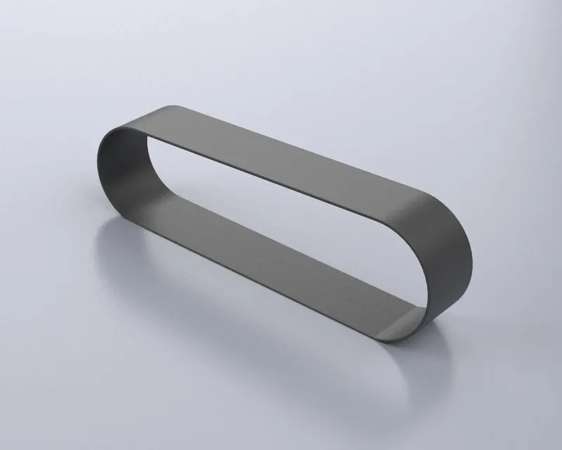
Rendered Image of Transmission Belt
Component 2: -
Kick Stand -
Modeling of the Kick Stand
Step 1 - Drawing
-
From the origin in the front plane, an ellipse is created, and from the origin in the right place, a spline is drawn.
-
By selecting the Reference geometry option to create a new plane at the spline's end point, another ellipse is created there.
Step 2 - Dimensions & Dynamic Relations
-
The larger ellipse has dimensions of 40 mm on the horizontal and 18 mm on the vertical, and it is made horizontal to the origin utilizing dynamic relation.
-
The end of the spline is located 202 millimeters horizontally and 110 millimeters vertically from the origin.
-
The newly generated plane's smaller ellipse has dimensions of 40 mm horizontally, and 18 mm vertically, and is brought horizontally to the origin via a dynamic relation.
Step 3 - Features
-
By choosing the spline with a lofted boss/base and a greater ellipse to a smaller ellipse, a loft is generated.
-
At both ends of the 13mm and 5mm dimensions, an elliptical dome is created.
-
By utilizing the "Split" cut body option, the material is removed from the kickstand's bottom to produce a flat face.
-
By creating a rectangle that is 8*28mm in size and utilizing an "Extruded cut" throughout, an extruded cut is produced at the larger end.
-
An extruded boss with a 9mm diameter is made at the larger end to serve as a pivot point for fixing the frame.
-
Fillets have 2mm and 0.5mm sharp edges, respectively.
Step 4 - Presentations
-
The entire component is made of a chromium plate.
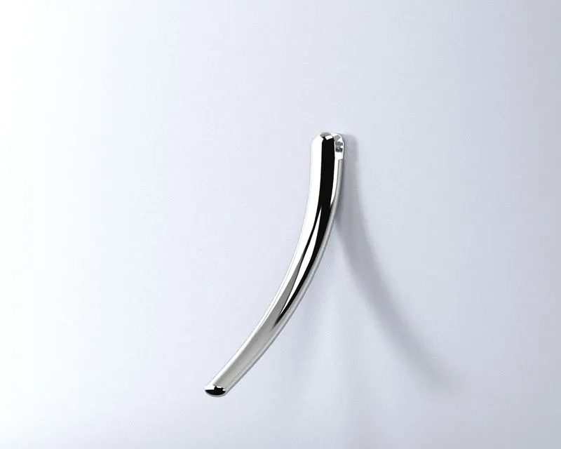
Rendered Image of Kick Stand
Component 3: -
Front Fender -
Modeling of the Front Fender
Step 1 - Drawing
-
In a vertical plane, a 3-point arc is drawn above the origin with a 6mm offset inward.
-
Using extend and trim entities, the sketch is finished.
-
To rotate the sketch, a construction line is created at the origin in a vertical plane with the necessary dimension.
Step 2 - Dimensions & Dynamic Relations
-
The center of the 160mm-wide, 125mm-radius arc is 280mm above the point of origin.
Step 3 - Features
-
Using the revolve extruded boss/bass command, the entire drawing is rotated 5 degrees in direction 1 and 130 degrees in direction two around the axis.
-
With the dynamic mirror turned on, a needed geometry form is constructed in the center plane using the spline and line commands. Using the sketch, a portion of the body is then deleted using the split command at the top end of the body.
-
The same process is used to cut out the required form in the bottom end of the body at the vertical plane.
-
The body's upper edges are all filled with a 6mm radius.
Step 4 - Presentations
- The entire piece is made from painted Siena.
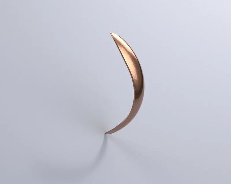
Rendered Image of Kick Stand
Component 4: -
Rear Fender -
Modeling of the Rear Fender
Step 1 - Drawing
-
In a vertical plane, a 3-point arc is drawn above the origin with a 6mm offset inward.
-
Using extend and trim entities, the sketch is finished.
-
The drawing is rotated using a construction line that is drawn at the origin in a vertical plane of the necessary dimension.
Step 2 - Dimensions & Dynamic Relations
- The Arc center is 90 mm above the origin and has a width of 364 mm and a radius of 290 mm.
Step 3 - Features
-
Using the revolve extruded boss/bass command, the entire drawing is rotated 10 degrees in direction 1 and 140 degrees in direction two around the axis.
-
To remove a portion of the body using a 3-point arc, a drawing of the desired form is made on the center plane. The split command is then used to remove the portion of the body using the sketch and construction lines.
-
The fender's remaining sharp edges are filled with a radius of 4 mm, and all four corner corners have a radius of 45 mm.
-
Using the shell command, the inside face of the fender is chosen and hollowed down to a depth of 4mm.
Step 4 - Presentations
The entire piece is made from painted Siena.
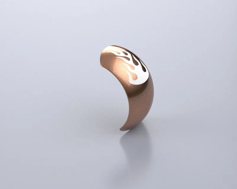
Rendered Image of Rear Fender
Component 5: -
Oil Tank -
Modeling of Oil Tank
Step 1- Drawing
- At the top plane, a sketch of the necessary geometry is created using lines, points, arcs, and dynamic relations like coincident, horizontal, and vertical.
Step 2 - Features
- Using the extruded bass/boss command, Sketch 1 is extruded with 170mm in Direction 1 and 10mm in Direction 2.
- Using lines and splines, sketch 2 is drawn on the front plane of the necessary geometry. Sketch 2 is then extruded using the through-all option in both directions without combining the two extrudes.
- To get the required three-dimensional form, the remains of the two extrudes are removed while keeping the common portion.
- Every sharp edge is filed to a radius of 10mm.
- Shell command is used to hollow out the whole component.
Step 3 - Presentations
-
The entire portion is painted, Siena.
-
The fillet that is produced is colored car white.
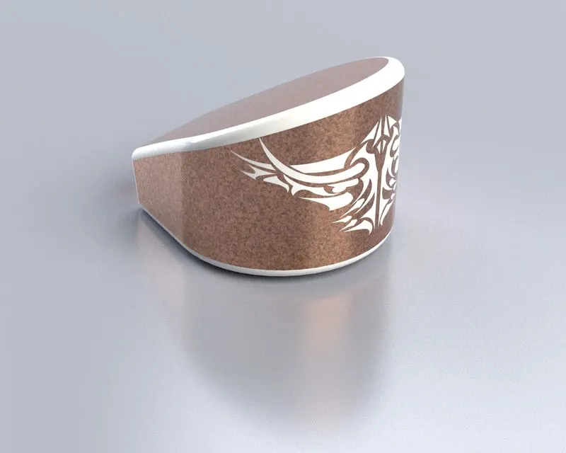
Rendered Image of Oil Tank
Component 6: -
Chain -
Modeling of Chain
Step 1- Drawing
-
On the front plane, a sketch is made that serves as a path for the chain to be fastened on the bigger and smaller sprockets using circles, arcs, and trim commands.
-
Utilizing the specified dimensions and relations, the sketch is fully described.
Step 2 - Drawing Blocks
-
Circles, arcs, and slot instructions are used to draw out chain links, and dimensions and relations are used to completely describe them.
-
Using the add block option, both links were created as blocks and saved.
Step 3 - Features
-
Links 1 and 2 have been installed and put in strategic locations.
-
For the necessary dimensions, pins are extruded from the drawing using the midplane extrude option, and their sharp ends are filled.
-
The Offset extrude option is used to extrude both links.
-
By separating the path into four sections to prevent link offset at curves, the curve-driven pattern command is utilized to produce links and pins all along the path.
-
To get linkages at both ends of the pins, all the links are mirrored about the midplane.
Step 4 - Presentation
-
The entire chain is made of a chrome plate.
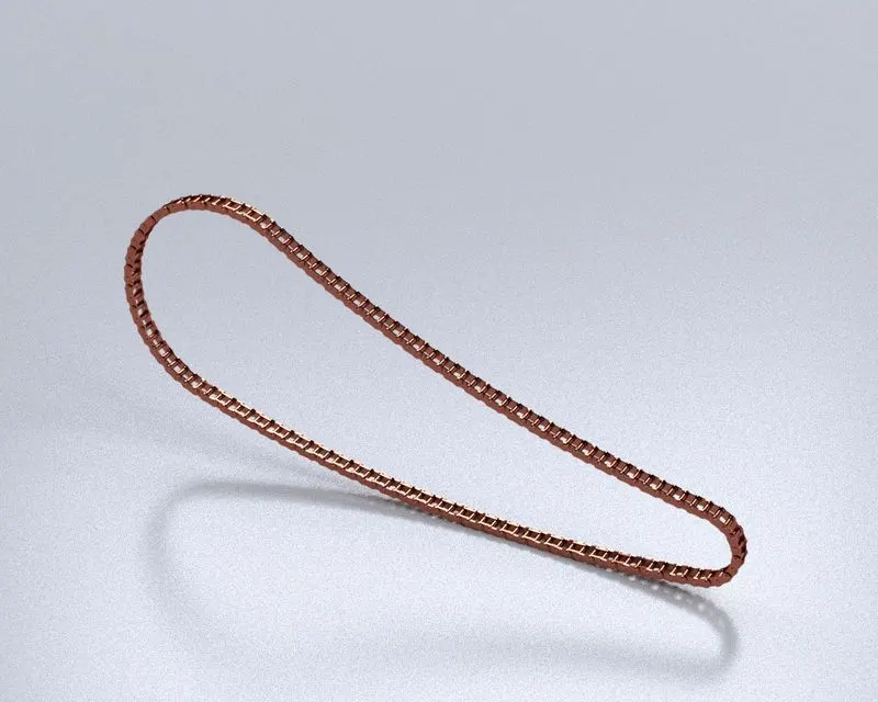
Rendered Image of Chain
Component 7: -
Pedal -
Modeling of Pedal
Step 1- Drawing
-
On the front plane, required dimensions and geometry are sketched using lines, arcs, circles, splines, and fillets.
-
Using the dimensions and dimensions, the sketch is fully specified.
Step 2 - Features
-
Using the Selected contour option, the whole drawing is extruded.
-
The first two circles are extruded for the desired length in the opposite direction, and they are utilized to attach the pedal to the main frame.
-
By sketching a design on the top plane and rotating it around its axis, a foot peg is produced, and a dome is produced at the end of the footpad.
-
Shifters are made by removing the remaining two circles from the surface and chamfering the ends of the shifters to the necessary proportions.
-
Footpad and shifter ridges are produced using an offset sketch and offset.
- Step 3 - Presentation
-
The entire Pedal is made of a chrome plate.
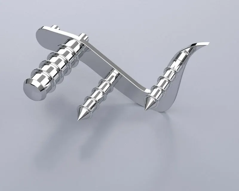
Rendered Image of Pedal
Component 8: -
Front Wheel -
Modeling of Front Wheel
Step 1- Drawing
- There's a requirement for the further adding and removal of materials. I created two rough body references by sketching on the right plane and using the revolve command.
- By using the hub's front face as a reference point, I sketched the rotor's dimensions and offsite the extrusion away from the hub.
- Next, I drew an 8mm circle on the front face/flat face of the extruded geometry and linearly patterned that hole at >mos3 and angled dimension of 142 degrees.
- Drawing the geometry of the Tyre on the front wheel using the convert entities option and using a reference of the rim curvature.
Step 2 - Features
- Constraints are drawn sketches and the Boss Extrude (For Extrude Command I deselect merge option) was then used to create spokes.
- Then, using the reference geometry as approximately extruded spoke elements, I deleted the curved-shaped material by making an extrusion cut on the center plane.
- Subsequently, I drew rib geometry to join the rim's extruded spokes.
- Once the spokes and outer periphery geometry were complete, I employed a circular pattern, using three equal-sized circles as vocal parts.
- After that, I added the outer circumference, spokes, and center hub by selecting the combined feature. as a single bodily component.
- On the flat face, I then created several replicas of the previously created hole using a circular pattern.
- Then, using the previous face as a guide, I created a constrained sketch for the caliper and extruded that. By combining with the rotor geometry and providing both with clearly defined directions.
- After that, the chamfer was given as a distance in both directions (8mm and 20mm) by using the top flat face of the caliper as a point of reference.
- A 4mm filter is offered on the sharing edge of the caliper.
- To construct the outer periphery of that sketch, I used the rotate option, after which I added the Tyre treads.
- The treads are drawn on the front plane by drawing four rectangles, giving them the appropriate relation, the specified dimensions, the origin, and the convert entity reference line.
- Then, remove 4 mm of material from the Tyre surface using offset extrude.
- After that, pattern the treads in a circular pattern as shown in the illustration.
Step 3 - Presentations
-
The Rim is painted Chromium Plate.
-
The Rotor is painted with Carbon Steel.
- The Caliper is painted with Siena.
-
The Tire is painted Matte Rubber.
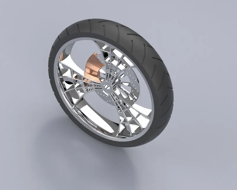
Rendered Image of Front Wheel
Component 9: -
Rear Wheel -
Modeling of Rear Wheel
- By modeling this file, I was able to have a thorough understanding of how to apply several drawing tools, like converting entities, offsetting entities, patterns, revolve, chamfer, etc.
Step 1- Drawing
- There's a requirement for the further adding and removal of materials. I created two rough body references by sketching on the right plane and using the revolve command.
- By using the hub's front face as a reference point, I sketched the rotor's dimensions and offsite the extrusion away from the hub.
- Next, I drew an 8mm circle on the front face/flat face of the extruded geometry and linearly patterned that hole at >mos3 and angled dimension of 142 degrees.
- Using the rotor's front-facing reference, I drew three-dimensional entities. I also made sure the entities weren't merged with any other geometries related to the other feature.
- I next added a 3 mm fillet to the extruded part's side edges.
- I then added a 3 mm fillet to the extruded part's side edges. 3. Using the front flat face, I then produced two-dimensional slots that were patterned as nos. Seven uses the circle and trim option.
- Drawing the geometry of the Tyre on the front wheel using the convert entities option and using a reference of the rim curvature.
Step 2 - Features
- Constraints are drawn sketches and the Boss Extrude (For Extrude Command I deselect merge option) was then used to create spokes.
- Then, using the reference geometry as approximately extruded spoke elements, I deleted the curved-shaped material by making an extrusion cut on the center plane.
- Subsequently, I drew rib geometry to join the rim's extruded spokes.
- Once the spokes and outer periphery geometry were complete, I employed a circular pattern, using three equal-sized circles as vocal parts.
- After that, I added the outer circumference, spokes, and center hub by selecting the combined feature. as a single bodily component.
- On the flat face, I then created several replicas of the previously created hole using a circular pattern.
- Then, using the previous face as a guide, I created a constrained sketch for the caliper and extruded that. By combining with the rotor geometry and providing both with clearly defined directions.
- After that, the chamfer was given as a distance in both directions (8mm and 20mm) by using the top flat face of the caliper as a point of reference.
- A 4mm filter is offered on the sharing edge of the caliper.
- Using the rotor's front-facing reference, I drew three-dimensional entities. I also made sure the entities weren't merged with any other geometries related to the other feature.
- I next added a 3 mm fillet to the extruded part's side edges.
- I then added a 3 mm fillet to the extruded part's side edges. 3. Using the front flat face, I then produced two-dimensional slots that were patterned as nos. Seven uses the circle and trim option.
- To construct the outer periphery of that sketch, I used the rotate option, after which I added the Tyre treads.
- The treads are drawn on the front plane by drawing four rectangles, giving them the appropriate relation, the specified dimensions, the origin, and the convert entity reference line.
- Then, remove 4 mm of material from the Tyre surface using offset extrude.
- After that, pattern the treads in a circular pattern as shown in the illustration.
Step 3 - Presentations
-
The entire portion is painted Chromium Plate.
-
The Rotor is painted with Carbon Steel.
- The Caliper is painted with Siena.
-
The entire portion is painted with Chromium Plate.
-
The entire portion is painted Matte Rubber.
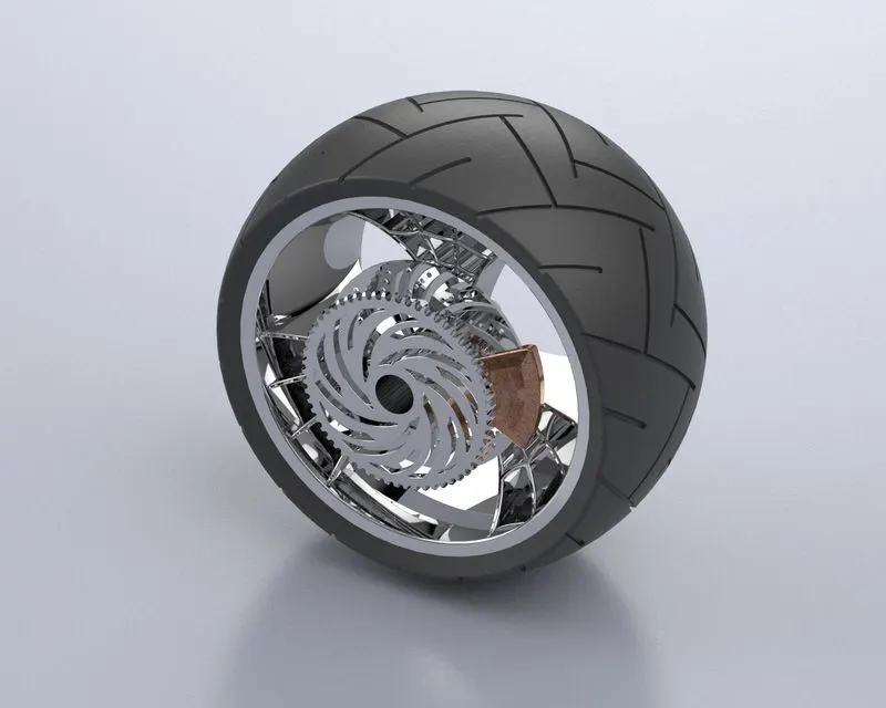
Rendered Image of Rear Wheel
Component 10: -
Front Fork -
Modeling of Front Fork
- By modeling this file, I was able to have a thorough understanding of how to apply several drawing tools, like converting entities, offsetting entities, patterns, revolve, chamfer, etc.
Step 1- Drawing
- I began modeling the first half of the front fork so that we could later mirror those all-solid geometries concerning the front flat facing.
- I drew a rough draught of the fork and rotated it, and I also drew half of the axle at the end of the session.
Step 2 - Features
- Next, by choosing the prescribed plane, I modeled a supporting member in the sketch.
- Using the Revolve Command, I then applied all the other features to the model and shifted the solid body.
- While modeling, I also came across the concept of the projected curve, as we are not getting the plane or curve which would follow the path for the handlebar.
- The smooth curve for the handlebar was obtained by creating two splines on the front and the right plane option is used.
- Then, using revolve command to create the reference plane on the sweep axis, I made a handlebar.
- Then, to create the path for a brake wire sweep, I used a similar method for the projected curve option.
- The solid bodies are then mirrored. Additionally, integrate the elements that were required for the body to function.
- The components and appearances of the components were then given dissimilar materials, and the headlight was given a unique appearance by going "forward" in appearance to make it realistic. Step 3 - Presentation
- For Handlebars and wire is painted Glossy Rubber.
- The entire Body of the Front Fork is a Painted Chromium Plate.
- For Front Light, I used to paint the Area light.
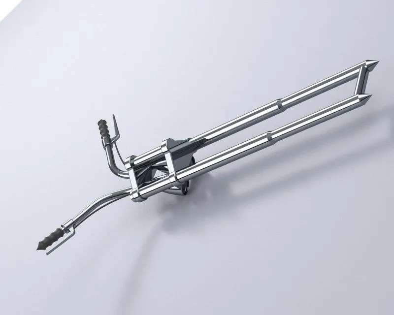
Rendered Image of Front Fork
Component 11: -
Chassis -
Modeling of Chassis
- The chassis or frame of a motorcycle acts as its skeleton.
- This base structure serves as the foundation for all a motorcycle's parts, including the suspension, wheels, fuel tank, seats, handlebars, and other elements that give a motorcycle its strength and good handling.
- Based on the financial constraints and performance requirements of the finished product, there are many distinct types of materials and shapes for motorcycle frames.
Step 1 - Features
- Sketch
- Convert Entities
- Project curve
- Offset
- Trim
- Sweep
- Split
- Revolve
- Cut extrude
- Fillet
- Combine
- Mirror
- Chamfer
- Dome
Step 2- Drawing
- Open a new part file, then rename some of the planes, such as the top plane to the bottom plane chassis and the front plane to the midplane chassis.
- We now begin drawing in midplane symmetry. Draw two concentric circles, one larger (40mm in diameter) than the other, with an offset of 4mm. Create these circles 185mm vertically and 880mm horizontally from the origin.
- Draw a horizontal line starting at 710mm and pointing right. Create a spline from this line's end and connect it to the circle's center. Put a weight of two hundred and make the bottom of the spline tangent to the line.
- Choose the bottom plane chassis, draw an arbitrary line above the origin that is 710mm long, and then draw a spline from the end of that line and connect it to the circle's center. Make the bottom of the spline vertical and give it a weight of 350mm. Also, make the spine tangent to the arbitrarily placed line.
- The curve we obtained after projecting the curve, as you can see, is not perfect, so we created another spline at a different plane (the right plane), starting from the circle's center and moving down to the origin. We then made the top of the spline horizontal 215mm and added weight of 165mm to the end of the spline.
- The convert entity option Now that the curve has been perfectly projected, we will use the swept option and create a circle to sweep around the spline.
- This is being mirrored around the face right now (midplane chassis).
- To get the same position as me, choose the appropriate plane, press Alt, and the arrow keys. Create a 275mm circle, align it vertically with the origin, and then draw a construction line from the center of the circle down to the origin. Make this point's end coincide with the swept parts outside the circle (choose the converted entity). now create a drawing with the precise dimensions provided in the illustration.
- Trim the unnecessary portion right now.
- If your sketch is over-defined, click the over-defined option at the bottom of your screen, check which dimension is excessive, and erase it if necessary.
- Extrusion the sketch now using a blind 22mm extrude and choose the merge result option.
- Now that we are going to edit this extruded part, select it, choose the regular sketch view, then choose the offset command and enter a 50mm offset.
- Two horizontal lines are drawn. One is 30mm and the other is 220mm above the original. Trim the unnecessary lines now and bring the offset line up to match the horizontal line.
- The direction up until next and then choose the extrude cut option. can use the 90mm and 44mm distance-distance options to chamfer the bottom outer edge. Give the inner and outer edges a 25mm fillet each.
- Give a fillet of 50mm at the edges and then draw two circles that are 4mm apart and 5mm apart from one another.
- The second plane is a vertex one, and we have now created a new plane1 with the first reference midplane chassis.
- Now, starting from the circle's center, draw a spline in plane 1 with a horizontal endpoint of 411mm and a vertical endpoint of 305mm. To sweep the circle inside the spline, use the sweep command. Step 3 - Presentation
- Siena paints the entire chassis.
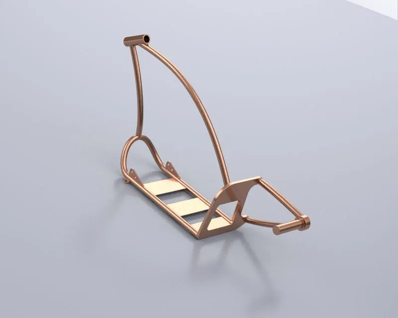
Rendered Image of Chassis
Component 12: -
Engine: -
Modeling of Engine
- Any vehicle's primary propulsion system is its engine, which burns an air-fuel mixture inside the engine cylinder to transform chemical energy into heat energy.
- Although Wrinkles and electric motors have been utilized, motorcycle engines are primarily two- or four-stroke internal combustion engines.
- Then, by turning the flywheel, clutch, gearbox, etc., heat energy is transformed into mechanical energy, which is then sent to the rear wheels.
Step 1 - Features
- Sketch
- Boss extrude
- Revolve
- Fillet
- Circular pattern
- Dome
- Cut extrude
- Chamfer
- Linear pattern
- Mirror
- Swept
- Project curve
- Split
Step 2- Drawing
- The motorcycle's blueprint is first put to the front plane. Subsequently, numerous sketches are made on the front plane, extruded, and given fillets.
- On the right plane, a sketch is now generated and then rotated to create a portion.
- Create a new plane about the correct plane, sketch it out, and then rotate it. Subsequently, sketch a design on the front plane and extrude.
- Now create the teeth for the chain using the circular pattern option. Likewise, repeat the process with the other sprocket.
- Then, on the newly made parts, make domes. On the front plane, a sketch is then made, cut, and extruded to provide holes for the sprocket. On the opposite sprocket, the same procedure is followed.
- The pieces are currently given specific fillets and chamfers.
- Then, another sketch is extruded after being drawn on the front plane. Then, another sketch is made on the same plane to create a connecting component.
- The front plane is then used to construct a new plane about the newly sketched design. On the freshly formed plane, a drawing is now produced, and it is then extruded.
- On the freshly constructed plane, two more sketches are once more produced and then extruded. The various sides are then given fillets and chamfers.
- On the same plane, a sketch is then created, sliced, and extruded to produce a form. Using the linear pattern option, this shape is replicated throughout the entire portion.
- Various fillets are then used after that. The generated cylinder is then extruded outward and given a dome after having a sketch drawn on it.
- Both sides of the cylinder have mirror images of this shape. The next step is to sketch a design on the front plane, extrude it, and then add fillets.
- Then, some pieces are eliminated using the split option. Then, using the mirror tool, duplicate the cylinder on the other side. The edges are now given some fillets.
- Then, after certain sketches have been extruded from the top plane and presented as fillets. Sketches are then created on the front plane, extruded, and chamfered.
- On the newly made sprocket, a little sketch is now produced, followed by an extrusion cut and the application of the fillet. The cut should then be duplicated throughout the sprocket using the circular pattern option.
- Once more, chamfers are provided. A second sketch is then made on the front plane and a second on the right plane.
- The exhaust tube is then created by using the sweep tool. The tube is then mirrored after that. All the parts have now been assembled. The top plane is then used to build an aircraft.
- Then a curve that was previously formed is added to another sketch that is made on the front plane. To create a sweeping portion, use this sketch as a guide.
- Once more, a drawing is made on the front plane and rotated to create the air intake. The portion is covered with a variety of fillets. A sketch is then generated on the top plane, cut extruded, and copied across the part using the circular pattern tool.
- Afterward, create the exhaust tube. Four curves are drawn on two distinct planes; each curve is created using the projected curves option, and each sweeping section is created using the swept option.
- Similarly, follow the same steps to create a second portion. The exhaust tip is then chopped with the split tool using the sketch that was previously drawn on the top plane.
- The spark plug's face and another curve on the front plane should then be sketched so that the spark plug wire can be created. Utilizing a similar process, create the same wire on the other spark plug.
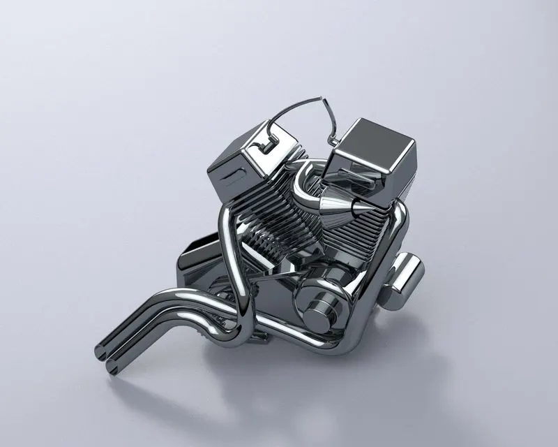
Rendered Image of Engine
Component 13: -
Gas Tank -
Modeling of Gas Tank
- The basic function of a gas tank is to hold gas. When the engine needs gas, it provides it.
Step 1 - Features
- Sketch,
- Surface sweep,
- Surface trim,
- Project curve,
- Surface loft,
- Surface boundary,
- Surface knit,
- Split line,
- Mirror,
- Surface extrudes,
- Fillet,
- Cut sweep,
- Shell.
Step 2- Drawing
- The labels Front plane, Top Plane, and Right Plane should all be changed to Mid Plane, Bottom Plane, and Front Plane, respectively.
- Insert the sketch with the given instructions after choosing the midplane fuel.
- Draw a horizontal construction line 831mm to the left and a vertical line 441mm from the end of the vertical line, selecting the midplane fuel.
- Selecting the front plane fuel and the right endpoint of the spline will now create a reference plane.
- Draw a spline as seen after selecting the new plane.
- Sweep surfaces along curves by clicking on them.
- Draw the splines as indicated by selecting the bottom plane.
- Create a reference plane by choosing the gas tank's left terminus and midplane, then draw on the plane.
- Choose the midplane fuel, then sketch a spline.
- Draw a straight line between the left terminus of the curve and the top point of the gasoline tank after choosing the front plane fuel, converting the curve, and making it for construction. Then choose the curve options, junction curves, and convert the final two curves.
- Make a surface loft now by choosing the surface loft.
- Pick the bottom plane, then draw it.
- Now choose the midplane, create a 6-point spline as indicated, choose the intersection curves option, and choose the final two designs.
- Now choose the boundary surface option, right-click the mouse, choose "Selection Manager," choose "Upper Curve," and then make your choices.
- All the bodies are connected by mirroring each other along the midplane.
- Select the bottom plane, then hold down the control key while selecting both edges, offset them by 30mm, draw a 3-point arc, and then specify the dimensions and power trim.
- Select the Split Lines option under Features and Curves, then choose both bodies.
- Now choose the extrude surface option, choose the two faces, extrude 25mm, and add a 20mm fillet to the edge.
- Select the border surface. Choose the loft surface, two edges, and guided curve now, then create a surface.
Knit all bodies together and make them solid. - All edges should be given a 5mm fillet. choose the midplane, then draw it.
- Choose the front plane, draw the path with a swept cut, and add a 2mm fillet to the inside edge as seen below.
- Apply appearances for a grey-colored seat fabric and a full-body painted Siena.
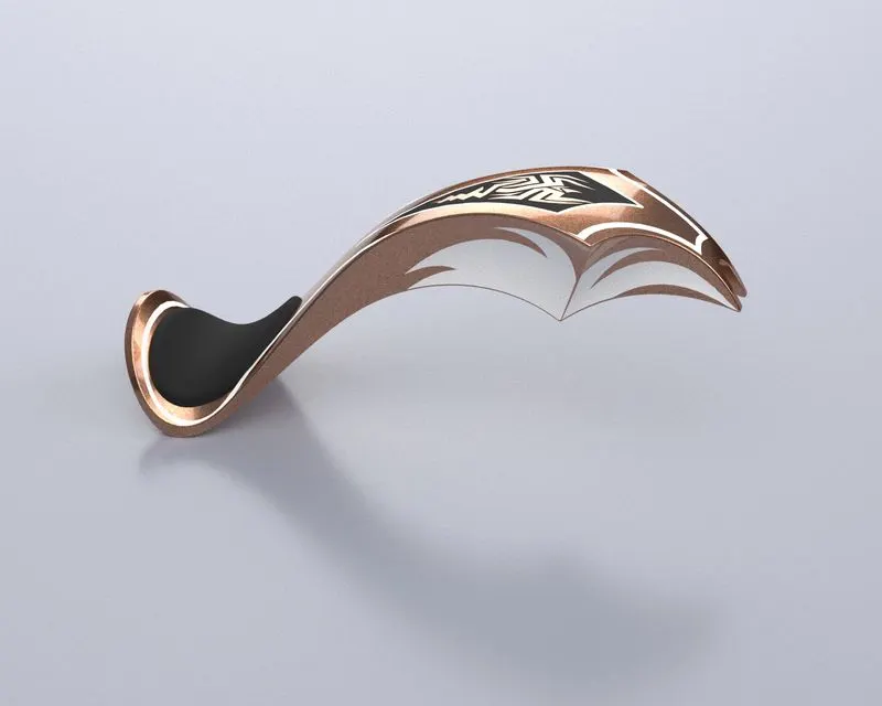
Rendered Image of Gas Tank
AMERICAN CHOPPER ASSEMBLED: -
- Putting parts together on an assembly line is the most common definition of assembly, but it can also refer to generating a finished product that fulfills its intended purpose.
- When a component is changed, the assembly is automatically updated, i.e. Rebuilding the document will either happen automatically or prompt the user to do so.
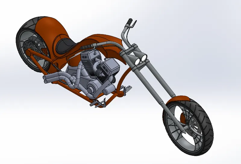
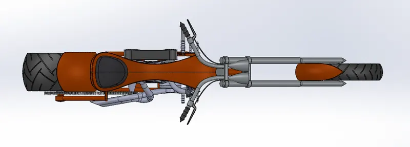
ISOMETRIC VIEW TOP VIEW
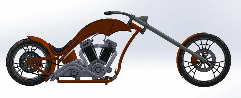
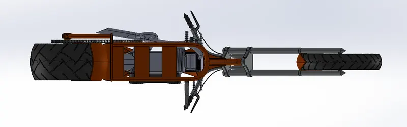
FRONT VIEW BOTTOM VIEW
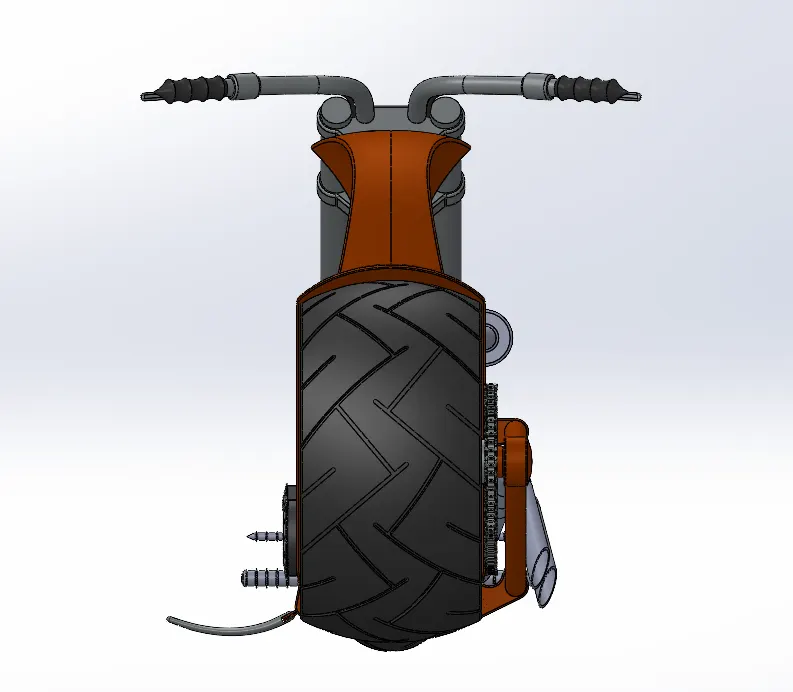
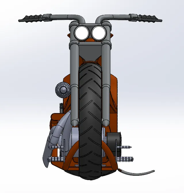
LEFT VIEW RIGHT VIEW
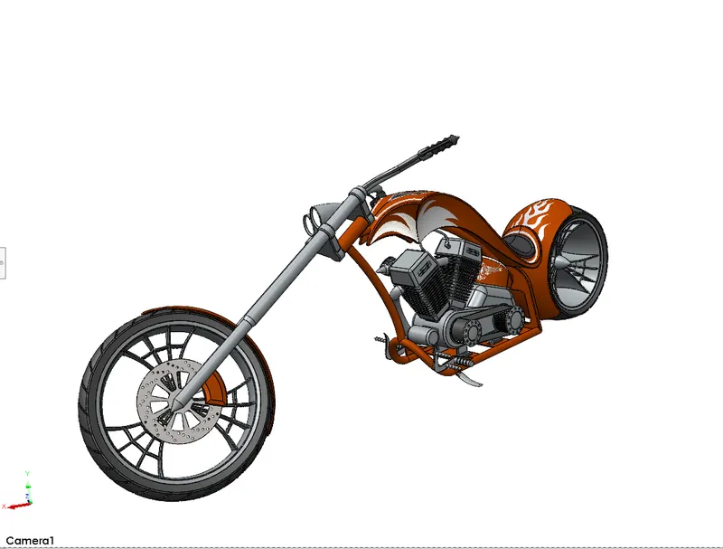
Camera View
The mates' feature is used to assemble the American chopper. Each component has a defined relationship with either the base component or the other components. The following are some relationships that are utilized to couple the components of an American helicopter:
- Concentric
- Coincident
- Parallel
- Tangent
- Width
DECAL APPLICATION, CAMERA SET-UP, & SCENES: -
The oil tank, gas tank, and rear fender all have decals on them. For adding the decals, we can use projected and label in the mapping process.
The view tab is where the camera is added; the view tab also contains the light. Final rendering is helped by camera setup.
Sceneries: Appropriate scenes are added to the model to increase realism.
RENDERING: -
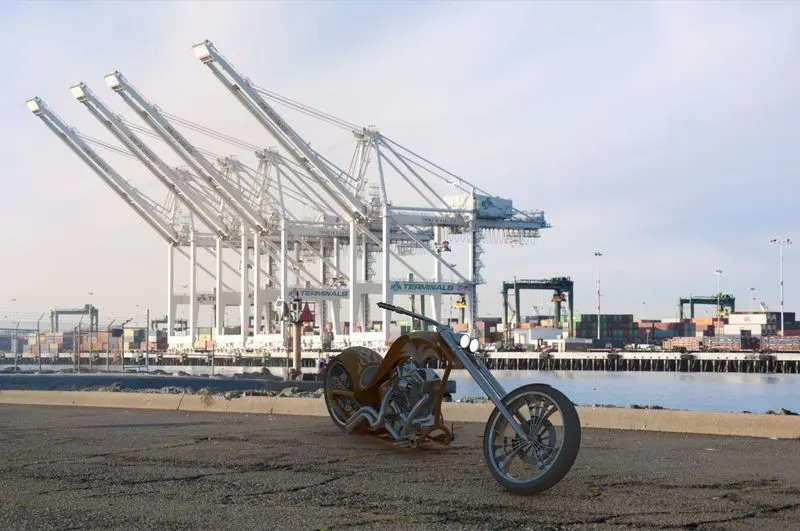
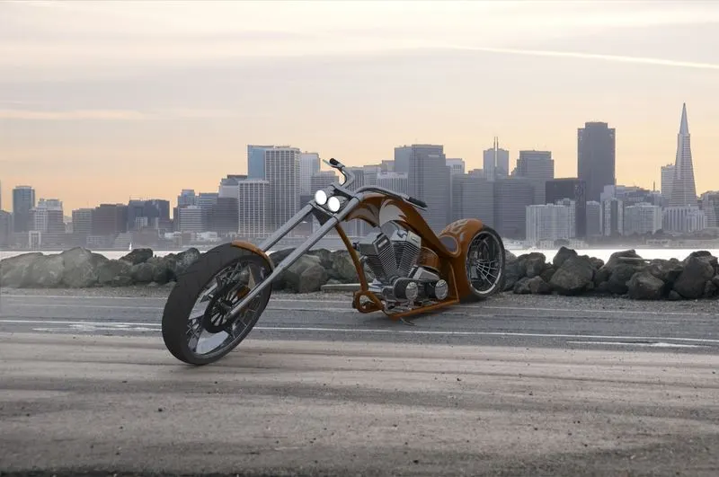
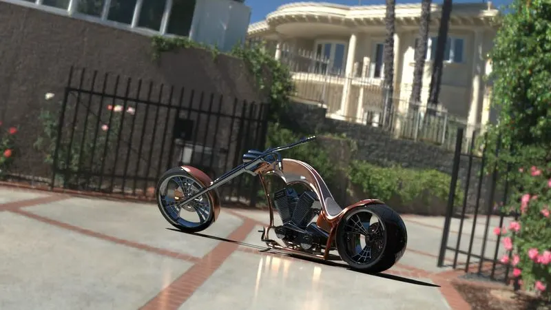
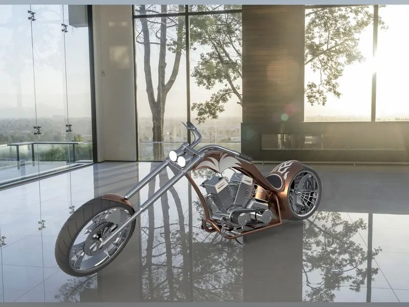
We used the Solid works visualize tool to depict the helicopter. We used render tools in Solid works to render individual pieces.
Procedure: -
- Visualize by importing the assembly model.
- Modify the model's appearance however you like.
- The model should have scenes.
- The final rendering is completed when finished.
FINAL RENDERS OF AMERICAN CHOPPER: -
CONCLUSION: -
The project on designing an American chopper with the photorealistic depiction in Solid works was designed and completed. As a result, SOLIDWORKS is used to design and construct the parts of the AMERICAN CHOPPER, and PHOTO VIEW 360 and SOLIDWORKS VISUALIZE are used to transform the parts into photorealistic images.