FINAL INDEPENDENT PROJECT
FRONT-END LOADER
Design, Assembly, and Rendering of a Front-End Loader using SolidWorks and SolidWorks Visualize: -
Zip File of All the Parts of Front-End Loader: -
Link: - https://drive.google.com/file/d/1kfL8LN4yJ4mRfvhYOjpnn7Ma8LXAsi79/view?usp=sharing
Objective: -
-
The main goal is to construct various Front-End Loader components using appropriate solid/surface modeling elements that will expedite the design process.
-
Recognizing the value of a detailed sketch enables us to change the proportions without error at any time.
It recognizes the Loader's construction process. -
I am experimenting with various appearances, sceneries, rendering parameters, etc. to produce high-quality rendered photos on SolidWorks photoview360 and SolidWorks Visualize.
Software Used: -
- I used the Solid Works 2021 Version.
- A parametric modeling program called SolidWorks is used to create/design models in sectors including the automotive and aerospace industries, among others.
- The model can be changed or modified at any time because the software is parametric.
- The modifications made to the part during modeling result in changes to the model's design.
Introduction of Project: -
- A tractor attachment known as a front-end loader is better suited for heavy-duty tasks in the agricultural, construction, and many other industrial sectors.
- The front loader is equipment that is often referred to as a shovel loader, scoop loader, or bucket loader.
- It typically has wheels and lifts and moves material using a square inclined bucket.
- Forks or hydraulically operated buckets were occasionally replaced by the loader assembly, which was mounted on the vehicle.
- The loader includes 40+ several types of bucket applications that are compatible with 140 different tractor models.
Features that I've used: -
- Boss Extrude: This function enlarges the item in three dimensions following the drawing plane.
-
Extrude Cut: This ability is used to cut or remove a 3D object in a straight line following a drawing.
-
Fillet: A feature used to create smooth, rounded internal or external edges to prevent sharp edges.
-
Lofted Boss/Base: The lofted boss is a characteristic that is utilized to create Complex Shapes. It accomplishes this by interpolating surfaces between different model cross-sections. Sketches, faces, or edges can be included in these cross-sections.
-
Split: The split tool is used to divide a single solid part into two solid pieces. It is used to project an object onto curved or planar surfaces.
-
Dome: A dome-shaped extrusion, such as an elliptical dome, can be made with this feature.
-
Shell: The shell feature is used to create a hollow space in a solid part by choosing the solid part's exterior wall and subsequently removing the inside portions. Additionally, it is applied to lessen a particular thickness.
-
Combine: The combined tool is used to integrate two solid elements that cross each other and form a single solid part.
-
Chamfer: The term "chamfer" refers to the process of making a sharp edge or corner tapered rather than perfectly square.
-
Linear Pattern: The pattern is created using a different number of instances than what is needed to do so.
-
Curve-Driven Pattern: A curve-driven pattern follows a previously designed curve to create any pattern.
-
Circular pattern: A feature that converts 3D features into circular patterns based on the number of insistences is known as a circular pattern.
-
Revolve boss base: The revolve function is utilized to create a 3D extrusion that is cylindrical or circular along with a specified reference axis according to a sketched design.
-
Revolve cut: Revolve cut is used to remove or lessen the extrusion of cylindrical spherical surfaces.
-
Copy/move the 3D body: This function allows you to move or copy the 3D body between two locations.
-
Mirror: By using the reference of the chosen plane, the mirror is used to reflect a feature or body.
-
Sweep: You can use this function to sweep any completely developed sketch alongside the path.
-
Sweep cut: Also known as a sweep feature, sweep cut performs a cut along the sweep path and is directly proportional to sweep.
-
Swept Surface: This technique creates a surface parallel to the path along which the curve is driven.
-
Boundary Surface: A surface between two finished surfaces is created using a boundary surface.
-
Loft Surface: A loft surface is used, together with a guide path, to create a loft between two profiles.
-
Knit surface: A knit surface lowers the space between two surfaces' edges and is used to knit their two free or open edges together.
-
Surface Trim: It has two modes: Standard and Mutual and are mostly used to remove material from a surface.
-
Projection Curve: A projection curve is a three-dimensional curve that is created by projecting two different two-dimensional curves onto two different planes.
-
Blocks: You can create, save, edit, and insert blocks from the sketch entities and drawing elements you frequently use, such as standard notes, title blocks, label positions, and so forth. You can also attach blocks to geometry or drawing views.
-
Trim entities: This tool is used to cut any extraneous lines or entities from a sketch.
-
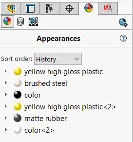
Appearances: A model's appearance describes its outward characteristics, such as color and texture. Physical qualities, which are determined by materials, are unaffected by appearances. Every substance has a default appearance.
ASSEMBLY: -
- Putting parts together on an assembly line is the most common definition of assembly, but it can also refer to generating a finished product that fulfills its intended purpose.
- When a component is changed, the assembly is automatically updated, i.e. Rebuilding the document will either happen automatically or prompt the user to do so.
MODELING OF Front-End Loader: -
I will sketch the Front-End Loader in Solid works with the help of sketch and feature tools. There are 15 Parts.
- Rear Body,
- Differential,
- Front Body,
- Boom Cylinder,
- Boom Rod,
- Connecting Rod,
- Rocker arm Cylinder,
- Rocker Arm Rod,
- Rocker Arm,
- Joint Connector Bolt,
- Excavator Boom,
- Bucker,
- Axial Rod,
- Rim,
- Tyre,
- Sub Assembly Tyre, Rim & Axle Rod,
- Final Assembly.
Parts I've Modelled: -
Part-1: -
Rear Body -
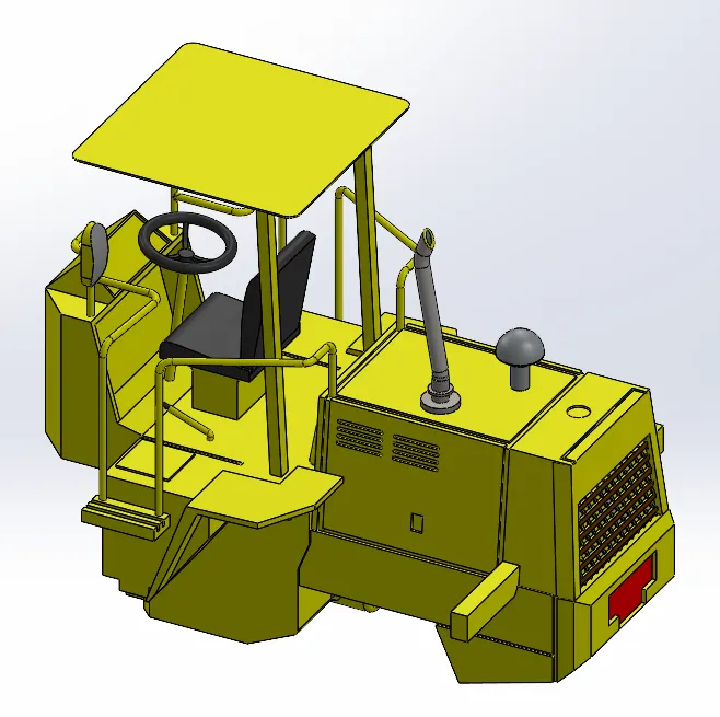
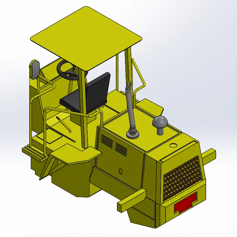
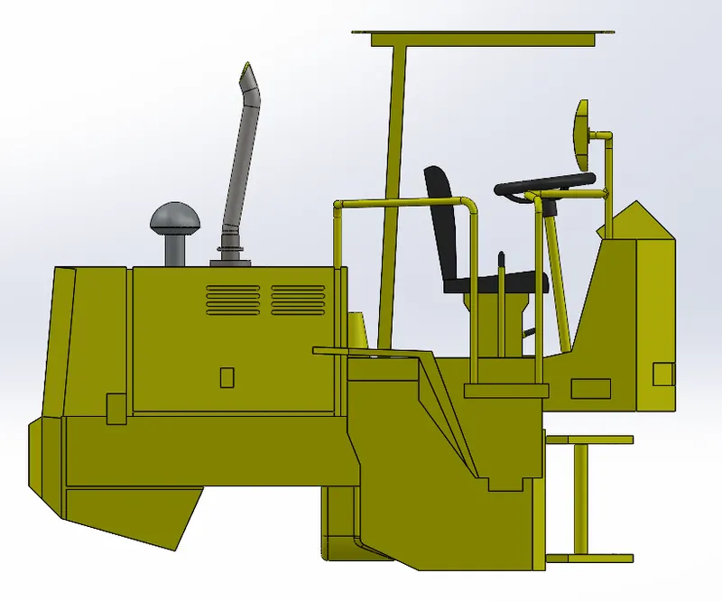
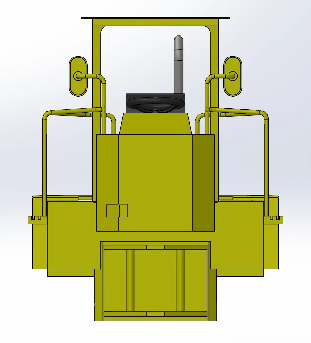
1. The Rear Body of the Front-End Loader has been created according to the proper dimensions.
Trimetric View
2. Modeling of the Rear Body: -
- Another name for the Rear body is the cab.
- Isolated cab: To operate the machine's horizontal movement and bucket, the operator sits in a cab immediately behind the hydraulic arms.
- A wide view improves visibility and keeps out dirt and other foreign objects.
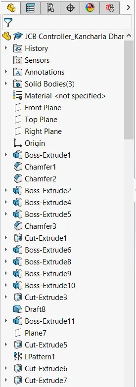
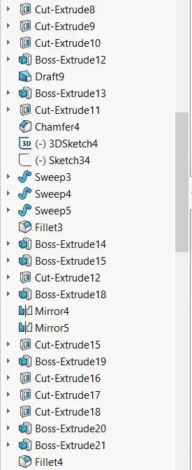
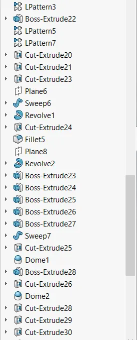
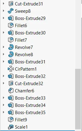
3. Feature Manager Design Tree: -
4. Presentations: -
5. All Views of the Rear Body: -
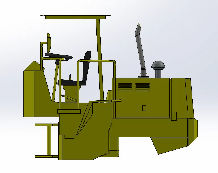
ISOMETRIC VIEW FRONT VIEW
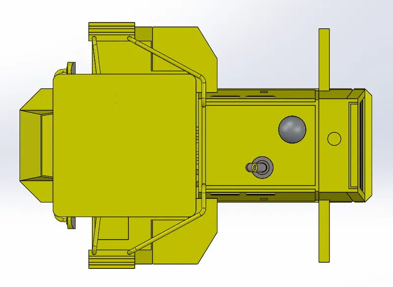
BACK VIEW TOP VIEW
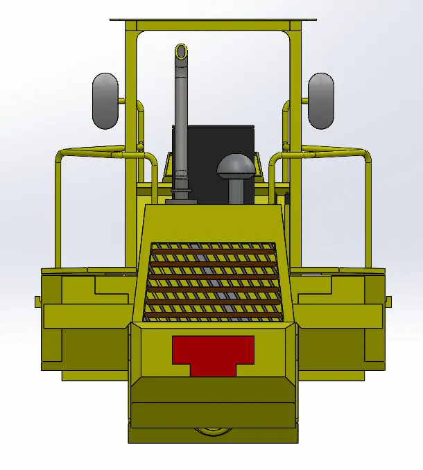
LEFT VIEW RIGHT VIEW
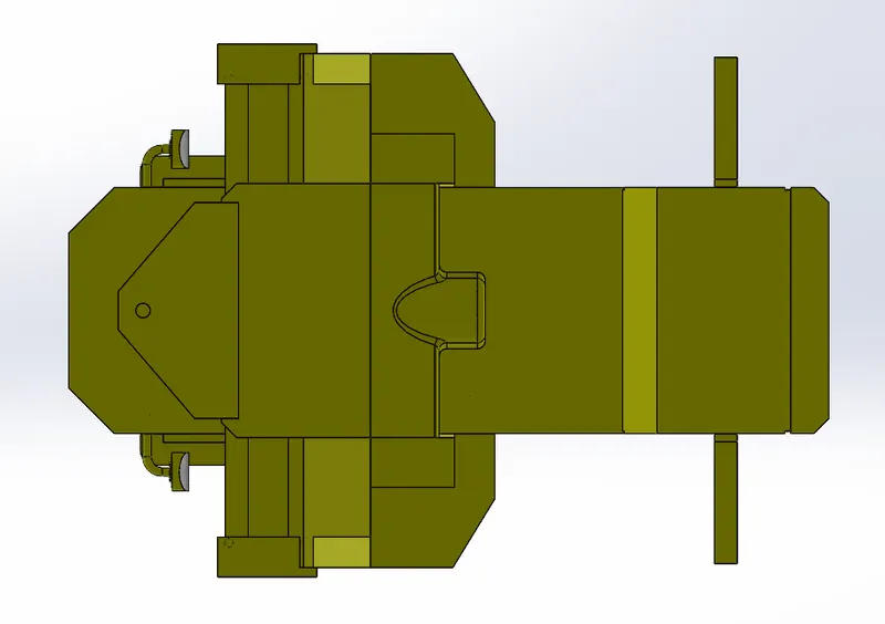
BOTTOM VIEW
Part-2: -
Differential -
1. The Differential of the Front-End Loader has been created according to the proper dimensions.
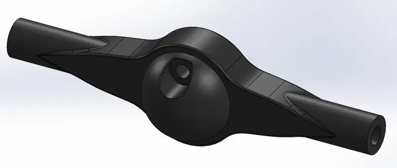
Trimetric View
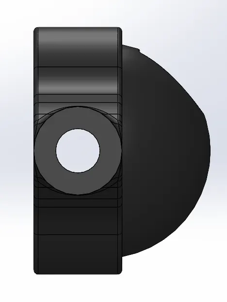
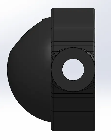
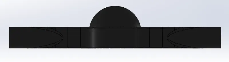
2. Modeling of the Differential: -
- The differential performs three functions:
- Directing engine power toward the wheels.
- It serves as the vehicle's last gear reduction, reducing the transmission's rotational speed just before it reaches the wheels.
- To deliver power to the wheels and enable them to spin at various rates (It is because of this that the differential is known by that name.)
3. Feature Manager Design Tree: -
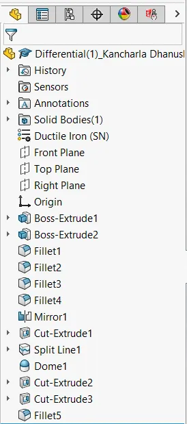
4. Presentations: -
5. All Views of the Differential: -
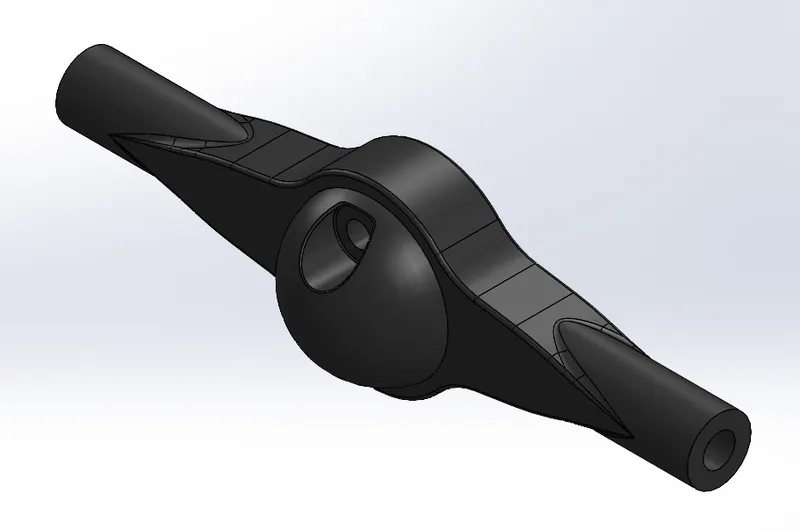
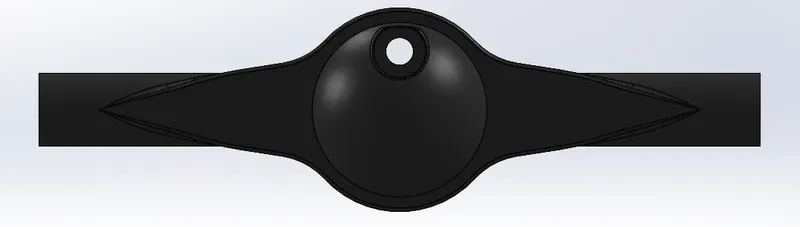
ISOMETRIC VIEW FRONT VIEW
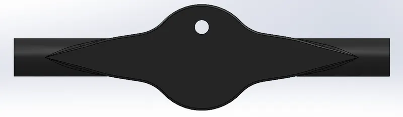
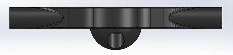
BACK VIEW TOP VIEW
LEFT VIEW RIGHT VIEW
BOTTOM VIEW
Part-3: -
Front Body -
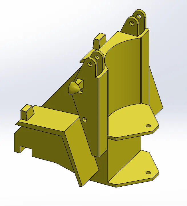
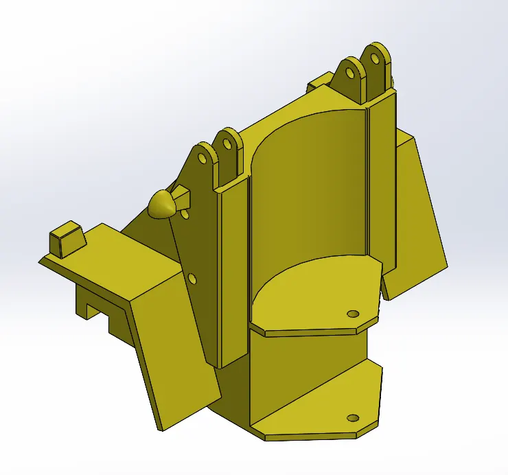
1. The Front Body of the Front-End Loader has been created according to the proper dimensions.
Trimetric View
2. Modeling of the Front Body: -
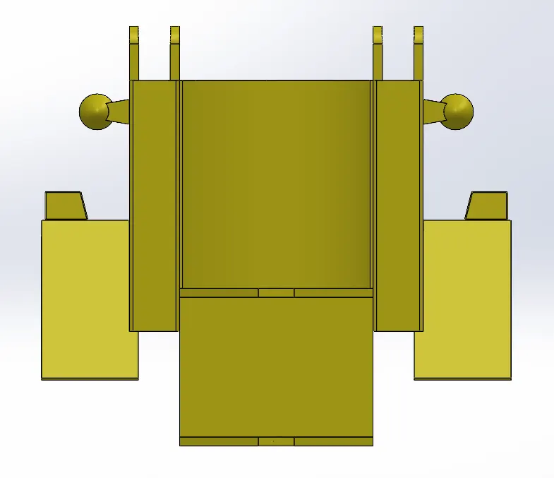
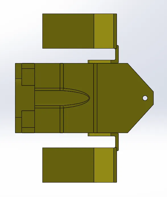
- Another name for the front body is the articulating hinge.
- This is the part that comes with lights, reflectors, mudguards, and connection points to join the arms and rear body.
3. Feature Manager Design Tree: -
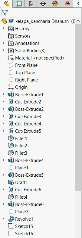
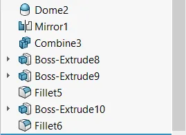
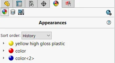
4. Presentations: -
5. All Views of the Front Body: -
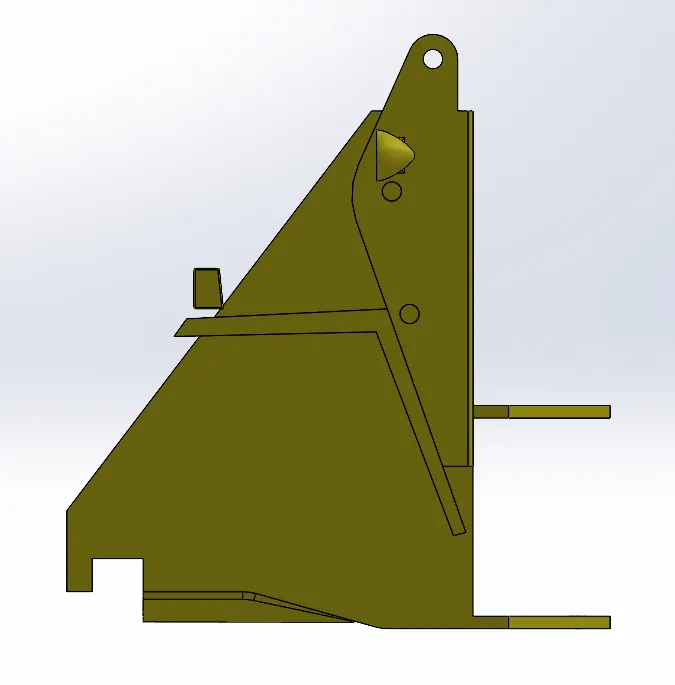
ISOMETRIC VIEW FRONT VIEW
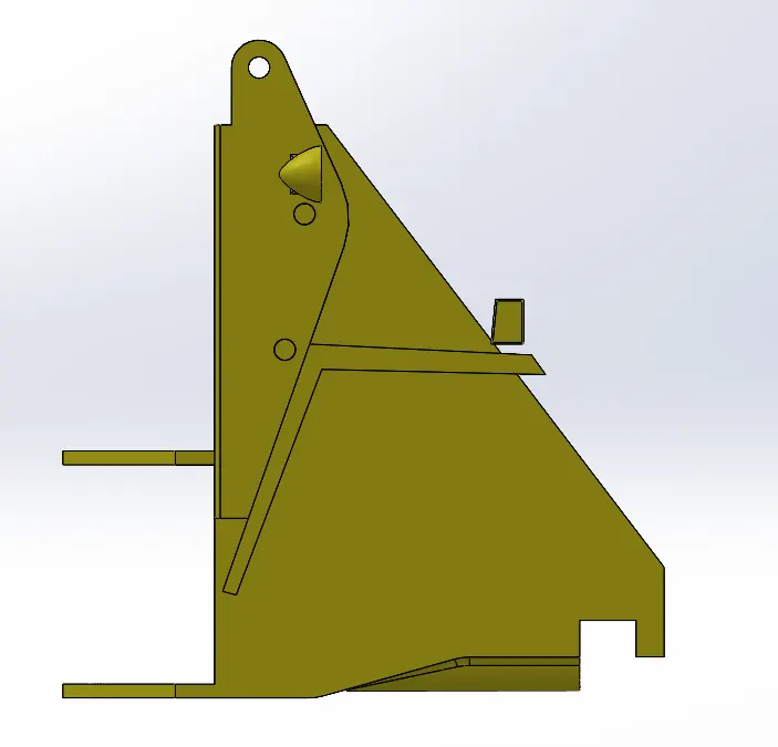
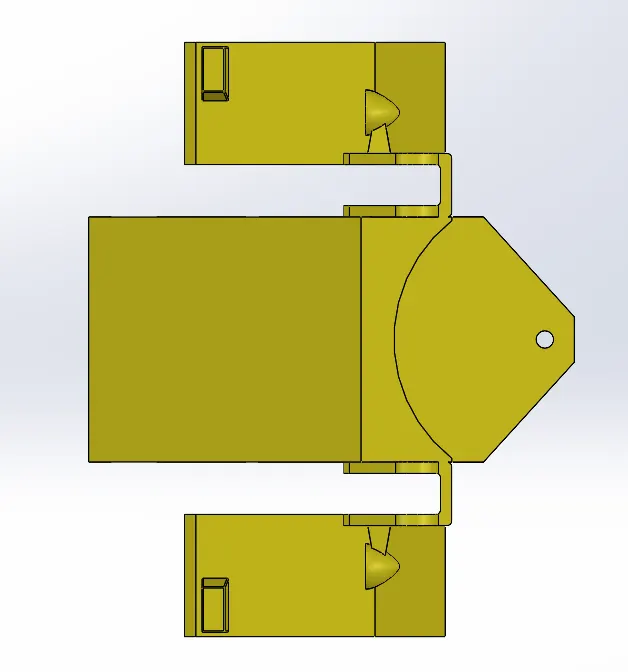
BACK VIEW TOP VIEW
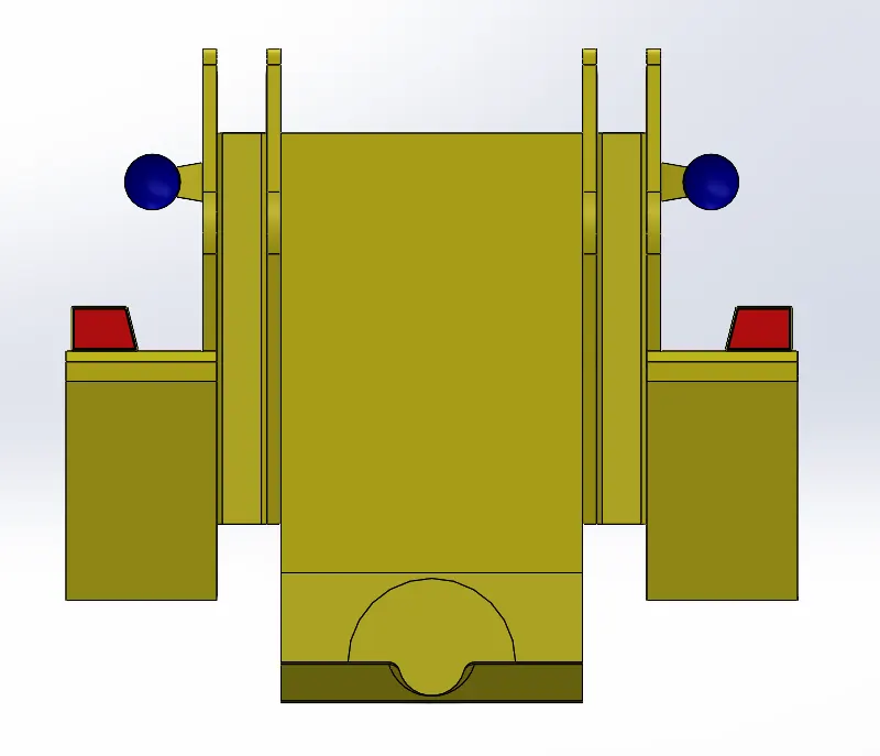
LEFT VIEW RIGHT VIEW
BOTTOM VIEW
Part-4: -
Boom Cylinder -
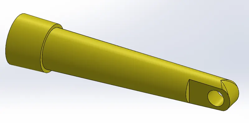
1. The Boom Cylinder of the Front-End Loader has been created according to the proper dimensions.
Trimetric View
2. Modeling of the Boom Cylinder: -
- Applications of boom cylinders are Excavators, Material handlers.
- Boom cylinders are used for moving the boom and stick.
- These cylinders are the largest in our product range.
- They are up to 3500 mm in length when extended and weigh almost 600 kg.
Advantages: -
- Exceptionally reliable anti-leakage features.
- Consistent, temperature-independent, material-friendly damping.
- Visually appealing and robust construction.
- For use under the harshest conditions.
- Low-temperature service.
- Long bearing life.
- Good cost-effectiveness for the customer.
- Heavy-duty design with smooth radius transitions.
- Can be used for high-bearing loads.
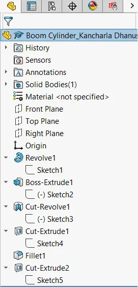
3. Feature Manager Design Tree: -
4. Presentations: -

5. All Views of the Boom Cylinder: -
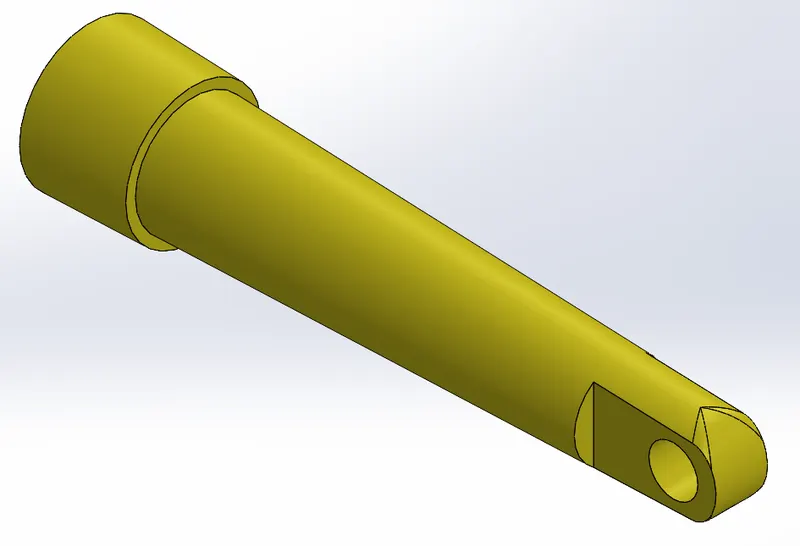
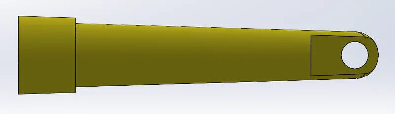
ISOMETRIC VIEW FRONT VIEW
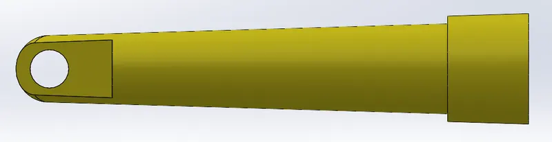
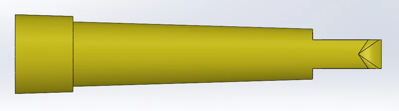
BACK VIEW TOP VIEW
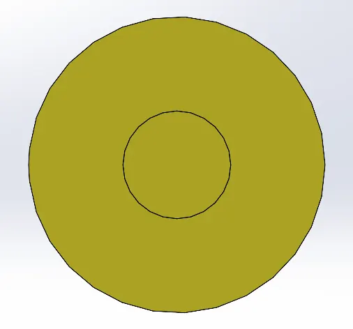
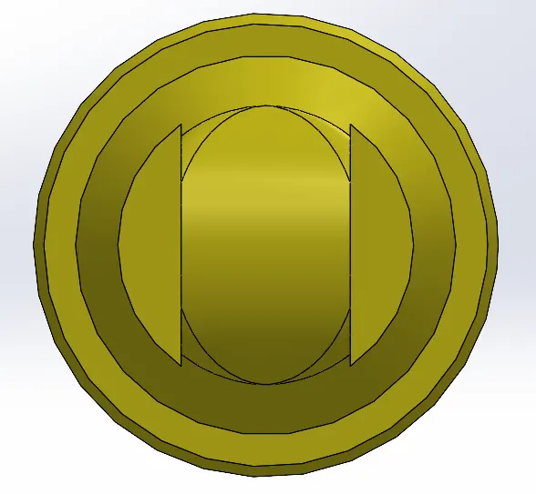
LEFT VIEW RIGHT VIEW
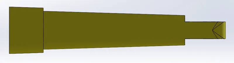
BOTTOM VIEW
Part-5: -
Boom Rod -
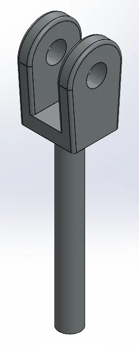
1. The Boom Rod of the Front-End Loader has been created according to the proper dimensions.
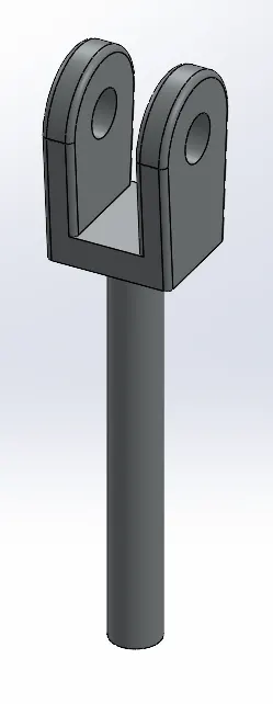
Trimetric View
2. Modeling of the Boom Rod: -
- The Front-end loader shown has its boom actuated by two hydraulic cylinders, one on each side of the machine, and the bucket is pivoted relative to the boom by a third hydraulic cylinder.
- Neglecting member weights and {friction effects, determine the cylinder force required for static equilibrium of the boom in the position shown with the total bucket load of 4kN.
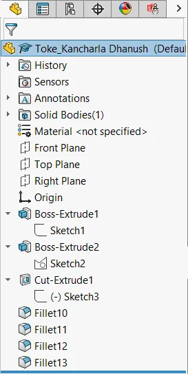
3. Feature Manager Design Tree: -
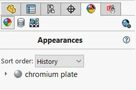
4. Presentations: -
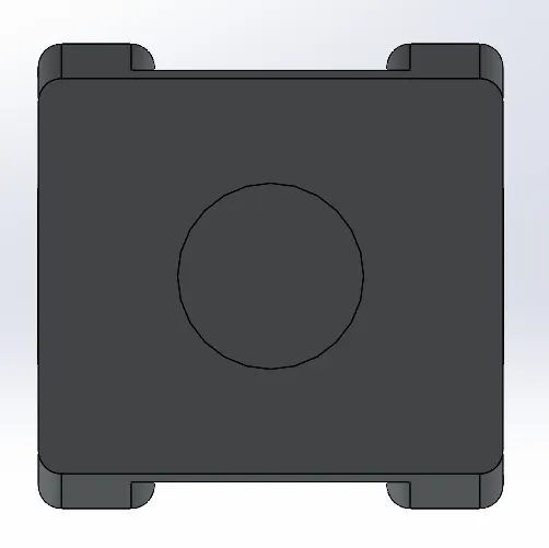
5. All Views of the Boom Rod: -
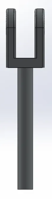
ISOMETRIC VIEW FRONT VIEW
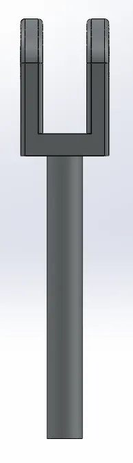
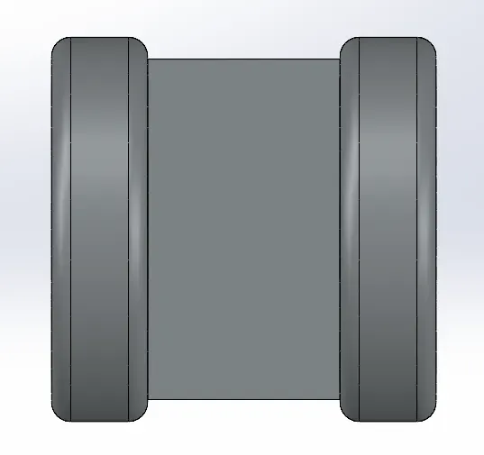
BACK VIEW TOP VIEW
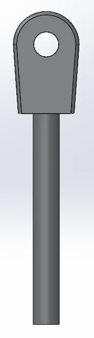
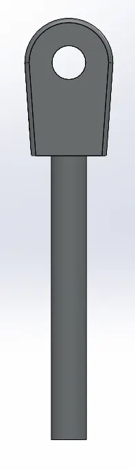
LEFT VIEW RIGHT VIEW
BOTTOM VIEW
Part-6: -
Connecting Rod -
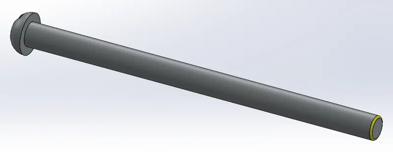
1. The Connecting Rod of the Front-End Loader has been created according to the proper dimensions.
Trimetric View
2. Modeling of the Connecting rod: -
- This connecting rod is used to connect the front body and rear body of the front-end loader.
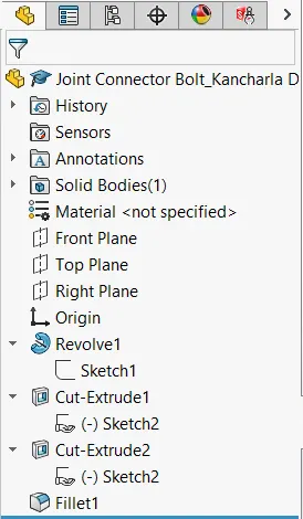
3. Feature Manager Design Tree: -
4. Presentations: -
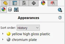
5. All Views of the Connecting rod: -
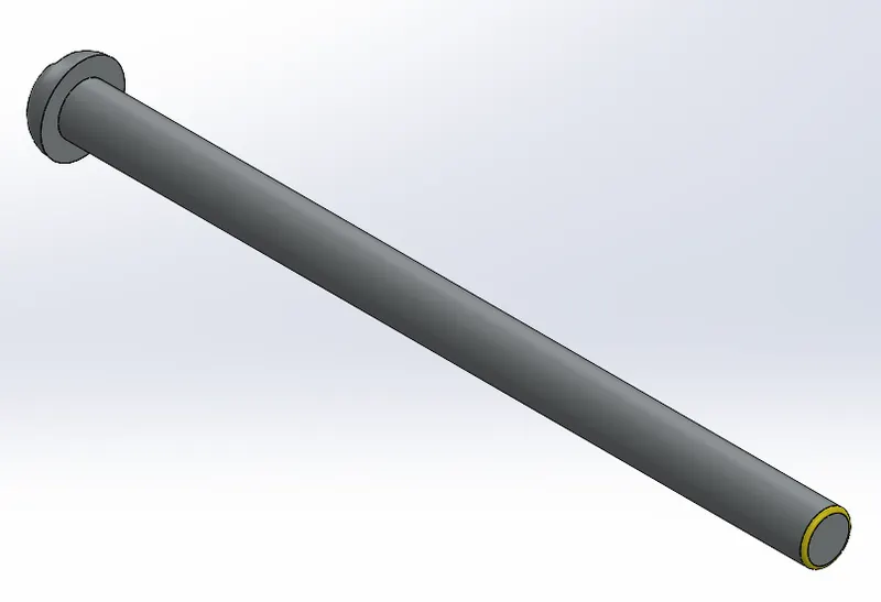

ISOMETRIC VIEW FRONT VIEW


BACK VIEW TOP VIEW
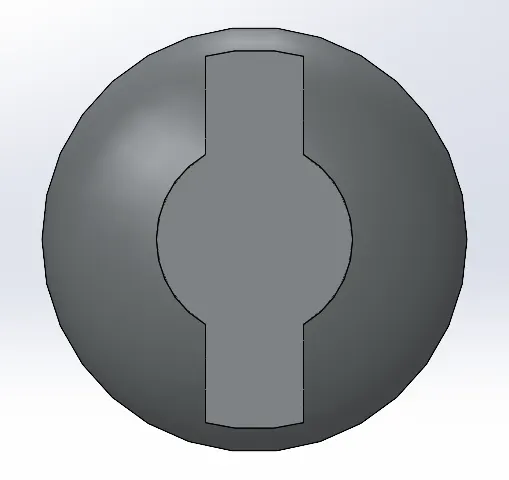
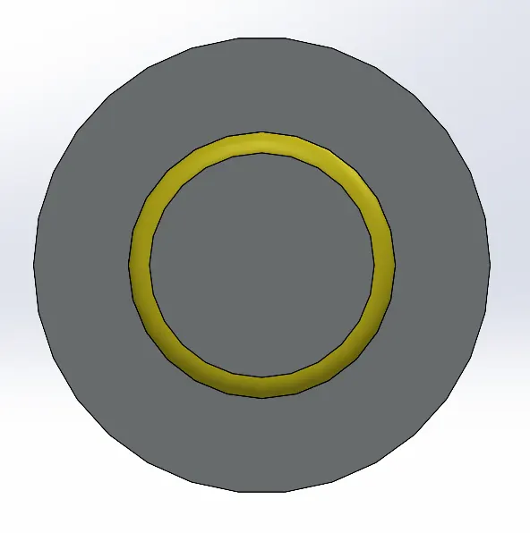
LEFT VIEW RIGHT VIEW
BOTTOM VIEW
Part-7: -
Rocker Arm Cylinder -
1. The Rocker arm cylinder of the Front-End Loader has been created according to the proper dimensions.
Trimetric View
2. Modeling of the Rocker Arm Cylinder: -
- Applications of rocker arm cylinders are Excavators, Material handlers.
- Rocker arm cylinders are used for moving the boom and stick.
- These cylinders are the largest in our product range.
- They are up to 3500 mm in length when extended and weigh almost 600 kg.
Advantages: -
- Exceptionally reliable anti-leakage features.
- Consistent, temperature-independent, material-friendly damping.
- Visually appealing and robust construction.
- For use under the harshest conditions.
- Low-temperature service.
- Long bearing life.
- Good cost-effectiveness for the customer.
- Heavy-duty design with smooth radius transitions.
- Can be used for high-bearing loads.
3. Feature Manager Design Tree: -
4. Presentations: -
5. All Views of the Rocker Arm Cylinder: -
ISOMETRIC VIEW FRONT VIEW
BACK VIEW TOP VIEW
LEFT VIEW RIGHT VIEW
BOTTOM VIEW
Part-8: -
Rocker Arm Rod -
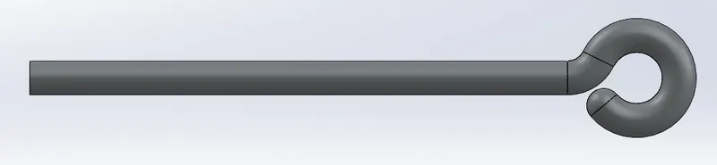
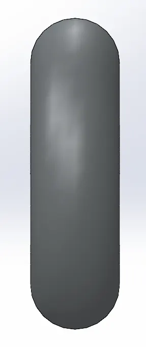
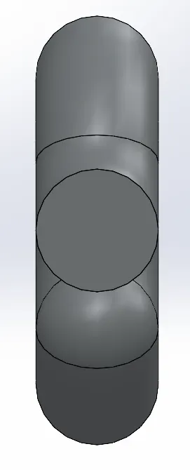
1. The Rocker arm rod of the Front-End Loader has been created according to the proper dimensions.
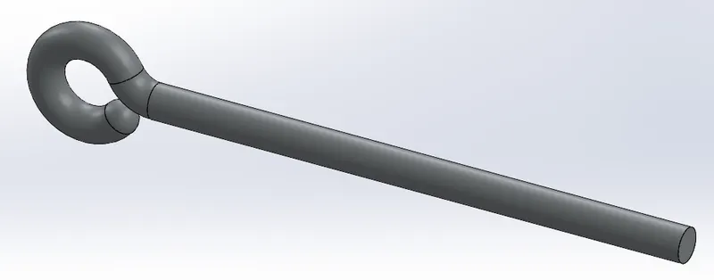
Trimetric View
2. Modeling of the Rocker Arm Rod: -
- The Front-end loader shown has its boom actuated by two hydraulic cylinders, one on each side of the machine, and the bucket is pivoted relative to the boom by a third hydraulic cylinder.
- Neglecting member weights and {friction effects, determine the cylinder force required for static equilibrium of the boom in the position shown with the total bucket load of 4kN.
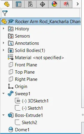
3. Feature Manager Design Tree: -
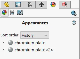
4. Presentations: -
5. All Views of the Rocker Arm Rod: -
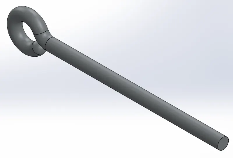
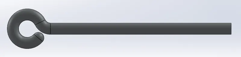
ISOMETRIC VIEW FRONT VIEW

BACK VIEW TOP VIEW
LEFT VIEW RIGHT VIEW

BOTTOM VIEW
Part-9: -
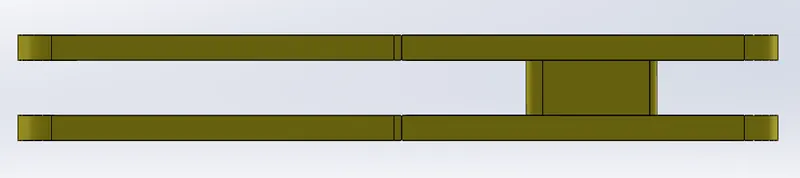
Rocker Arm -
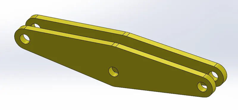
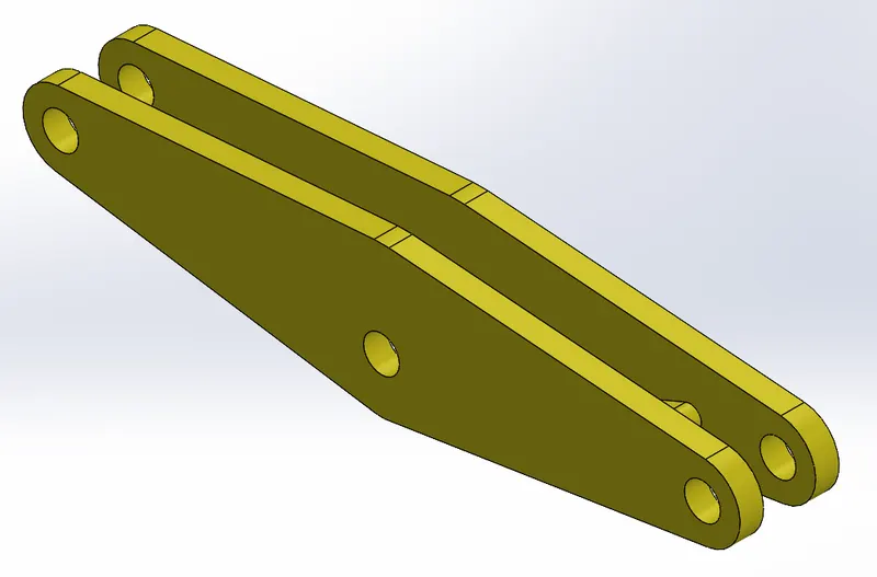
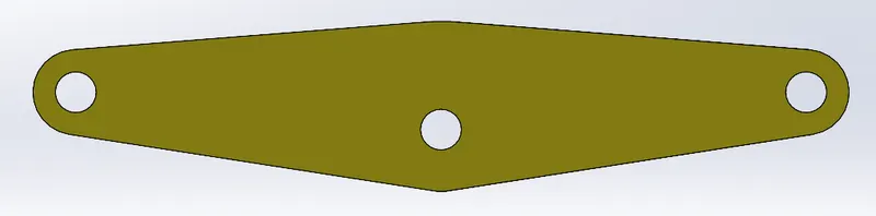
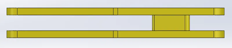
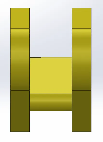
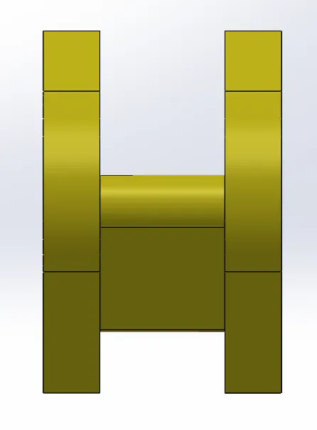
1. The Rocker arm of the Front-End Loader has been created according to the proper dimensions.
Trimetric View
2. Modeling of the Rocker Arm: -
- The rocker's arm is the part responsible for transmitting the movement of the camshaft towards the intake and exhaust valves of the engine, a process that occurs through the direct contact of these parts with the tappets and according to the movement of the shaft.
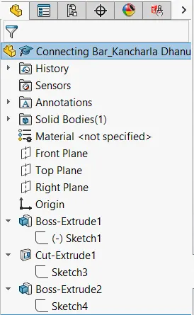
3. Feature Manager Design Tree: -
4. Presentations: -
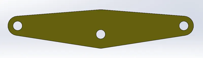
5. All Views of the Rocker Arm: -
ISOMETRIC VIEW FRONT VIEW
BACK VIEW TOP VIEW
LEFT VIEW RIGHT VIEW
BOTTOM VIEW
Part-10: -
Joint Connector Bolt -
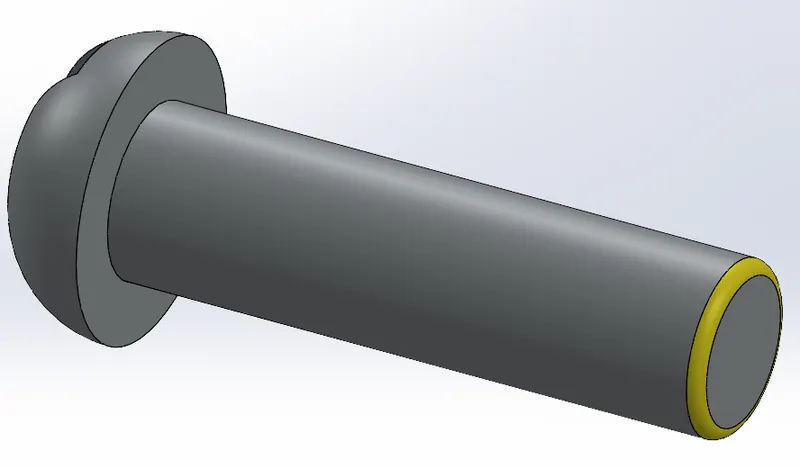
1. The Joint Connector of the Front-End Loader has been created according to the proper dimensions.
Trimetric View
2. Modeling of the Joint Connector Bolt: -
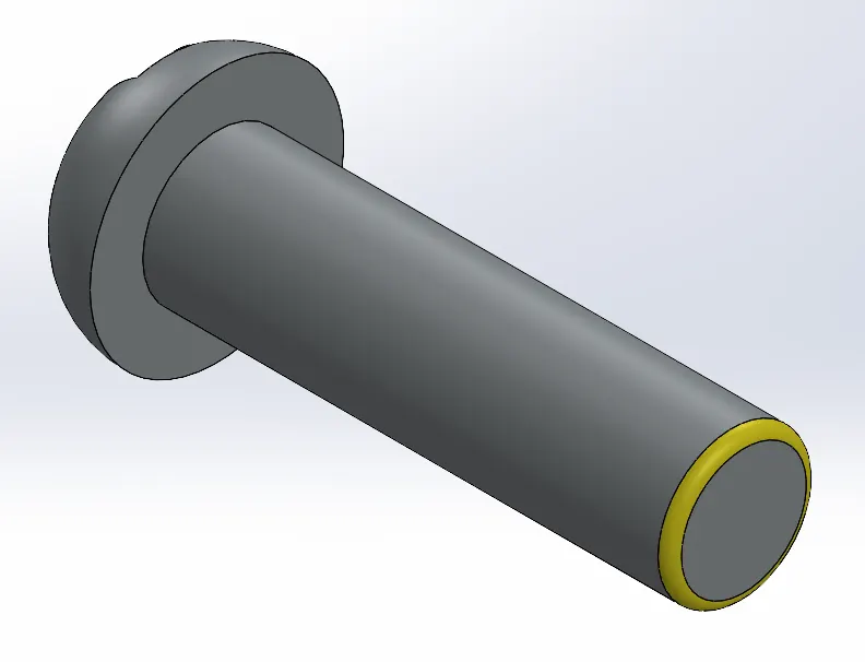
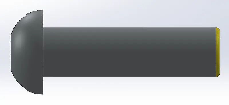
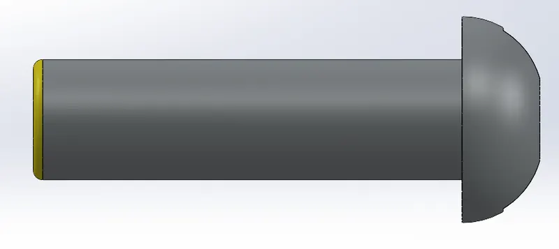
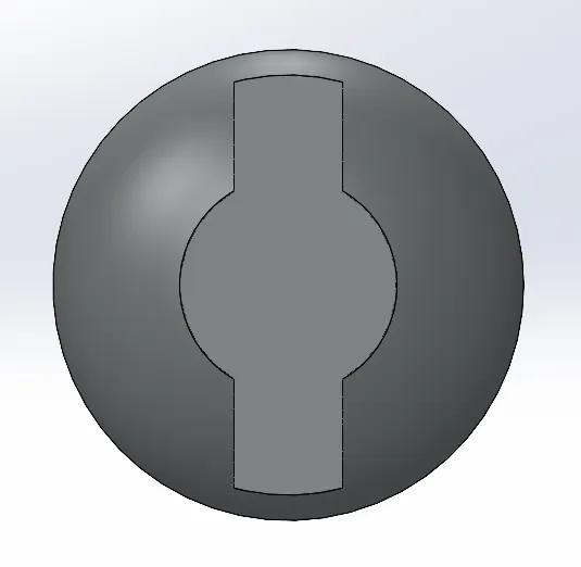
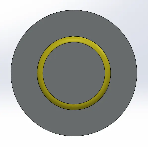
- This Joint connector bolt is used to connect or link the joints of links tightly and it comes with bearings to move and create friction.
3. Feature Manager Design Tree: -
4. Presentations: -
5. All Views of the Joint Connector Bolt: -
ISOMETRIC VIEW FRONT VIEW
BACK VIEW TOP VIEW
LEFT VIEW RIGHT VIEW
Part-11: -
Excavator Boom -
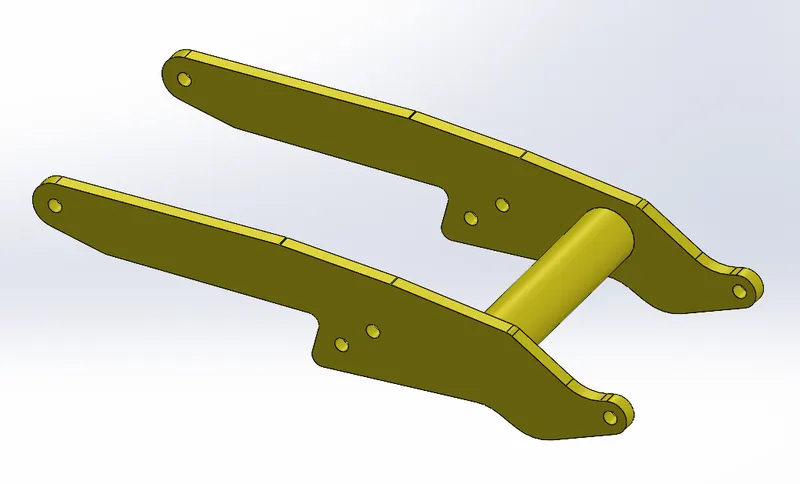
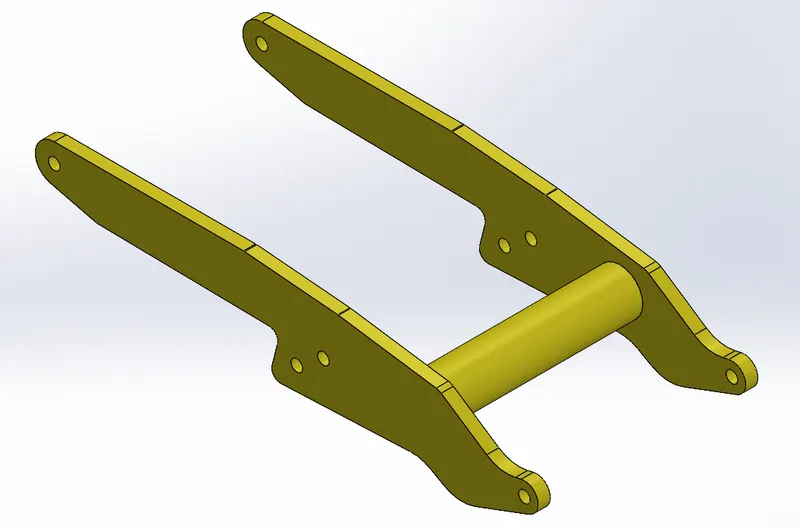
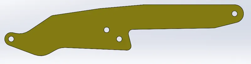
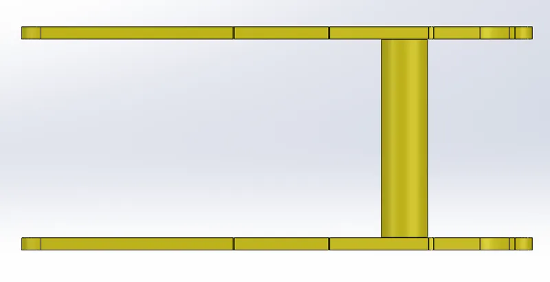
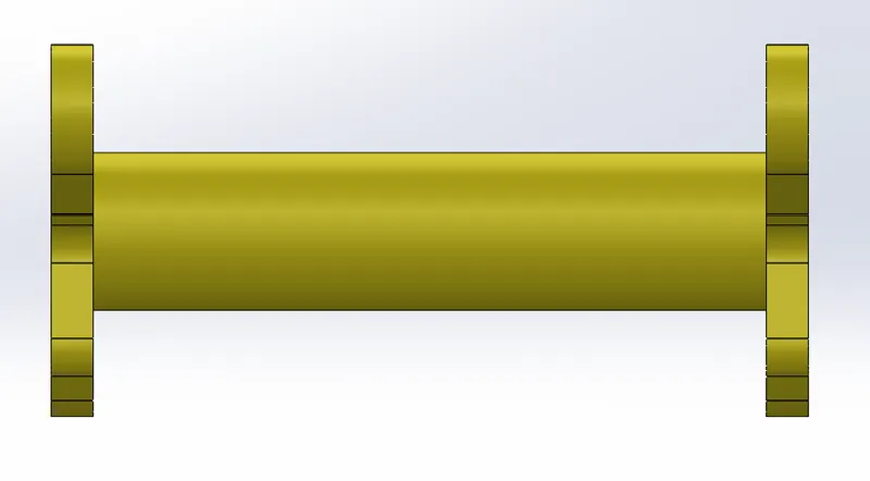
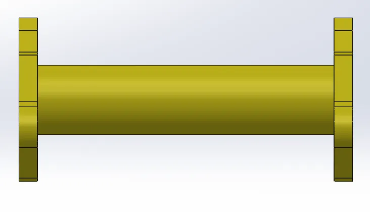
1. The Excavator Boom of the Front-End Loader has been created according to the proper dimensions.
Trimetric View
2. Modeling of the Excavator Boom: -
- The Excavator boom is another option on some excavator models.
- A two-piece offset boom knuckles off to the right or the left.
- If, for example, you’re working in a tight alley with limited swing, you can knuckle the boom over so that it digs in line with one of the tracks up next to a structure.
- Note on large machines it will decrease your lifting capacity because you have a knuckle and the cylinders out on the boom, so you’re increasing the weight that’s out in front of the machine.
- Two-piece offset booms are more expensive and can require additional maintenance.
- This boom configuration is popular in cities with extremely tight workspaces.
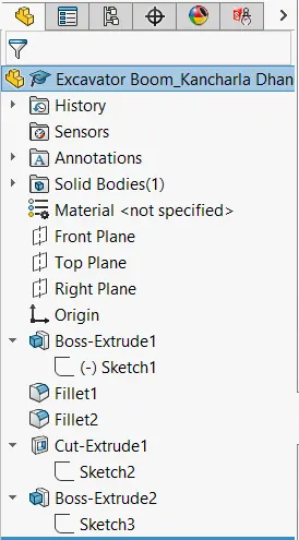
3. Feature Manager Design Tree: -
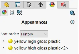
4. Presentations: -
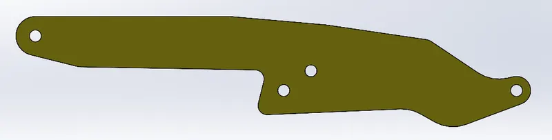
5. All Views of the Excavator Boom: -
ISOMETRIC VIEW FRONT VIEW
BACK VIEW TOP VIEW
LEFT VIEW RIGHT VIEW
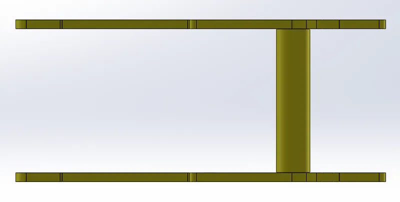
BOTTOM VIEW
Part-12: -
Bucker -
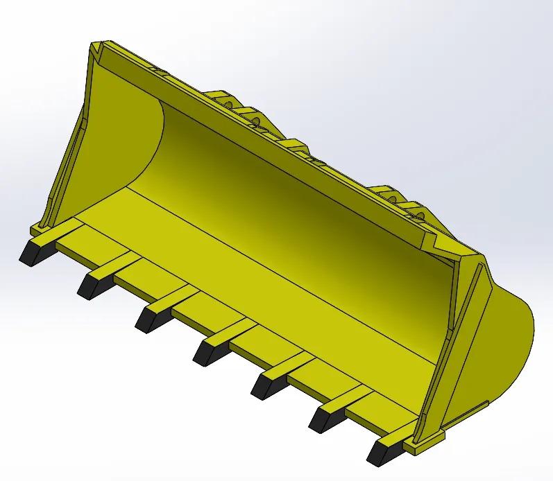
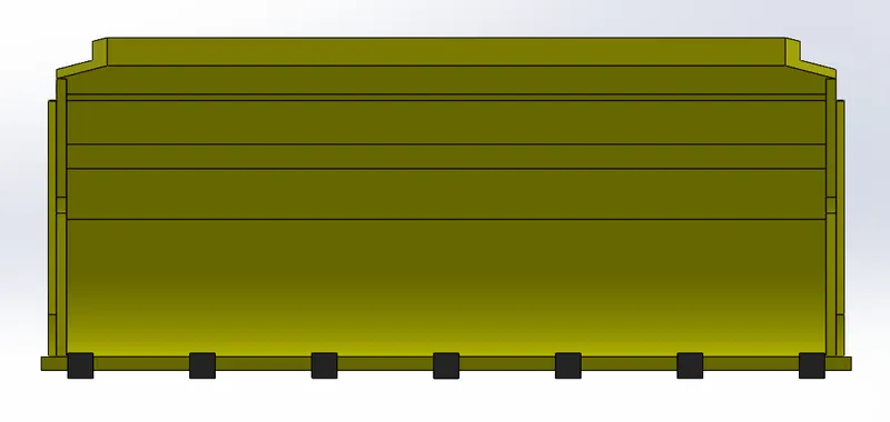
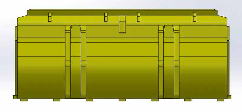
1. The Bucker of the Front-End Loader has been created according to the proper dimensions.
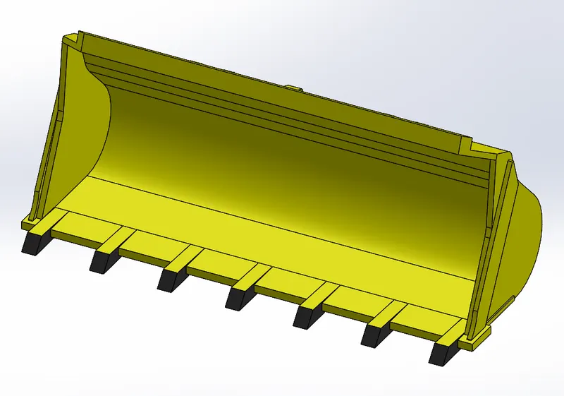
Trimetric View
2. Modeling of the Bucker: -
-
A tractor loader bucket is a versatile item that can be used in several different practical applications, this includes grain loading.
-
In addition to regular loading buckets, we offer a high tip variety.
-
This extremely practical variation of the tractor loader bucket facilitates extra load height and forward tip.
-
The products can be used in tandem with high-sided vehicles, such as hoppers and walking floor trailers.
-
This is an incredibly significant factor that can help a business to optimize loading efficiency and productivity – positively impacting profitability.
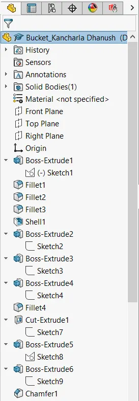
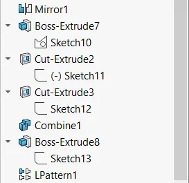
3. Feature Manager Design Tree: -
4. Presentations: -
5. All Views of the Bucker: -
ISOMETRIC VIEW FRONT VIEW
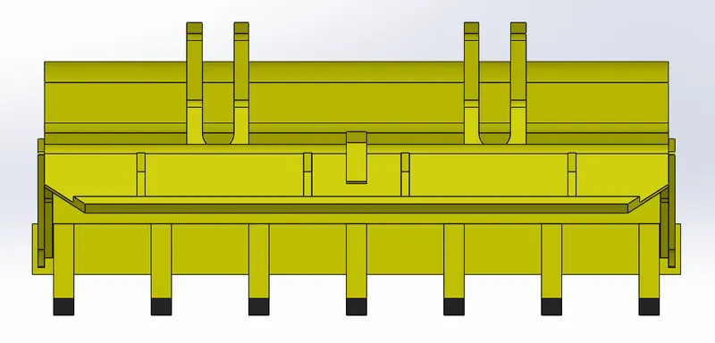
BACK VIEW TOP VIEW
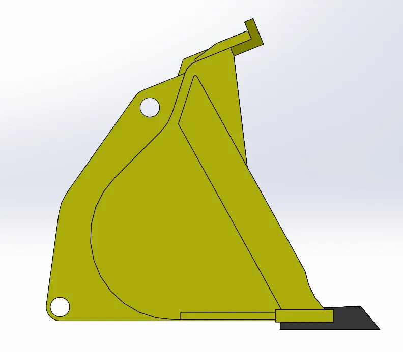
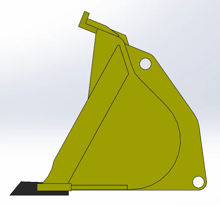
LEFT VIEW RIGHT VIEW
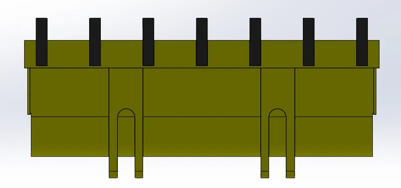
BOTTOM VIEW
Part-13,14,15: -
Axial Rod, Rim, Tyre -
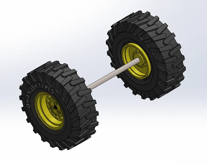
1. The Axial Rod, Rim, and Tyre of the Front-End Loader have been created according to the proper dimensions.
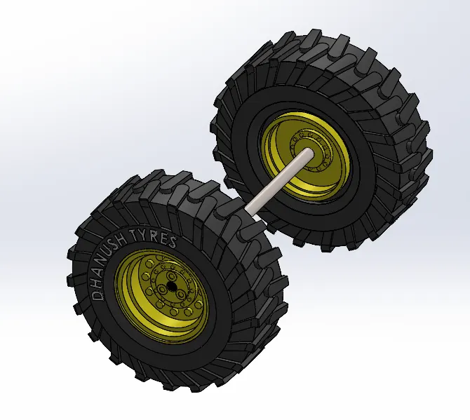
Trimetric View
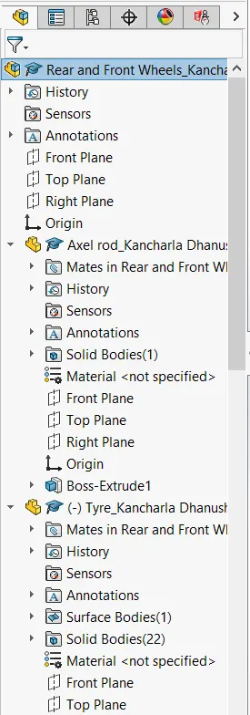
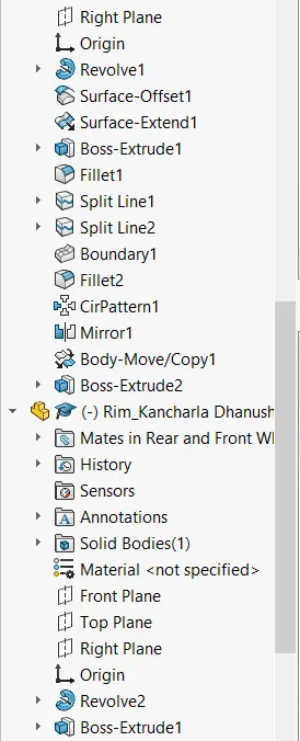
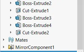
2. Feature Manager Design Tree: -
3. Presentations: -
4. All Views of the Axial Rod, Rim, Tyre: -
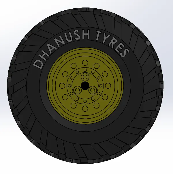
ISOMETRIC VIEW FRONT VIEW
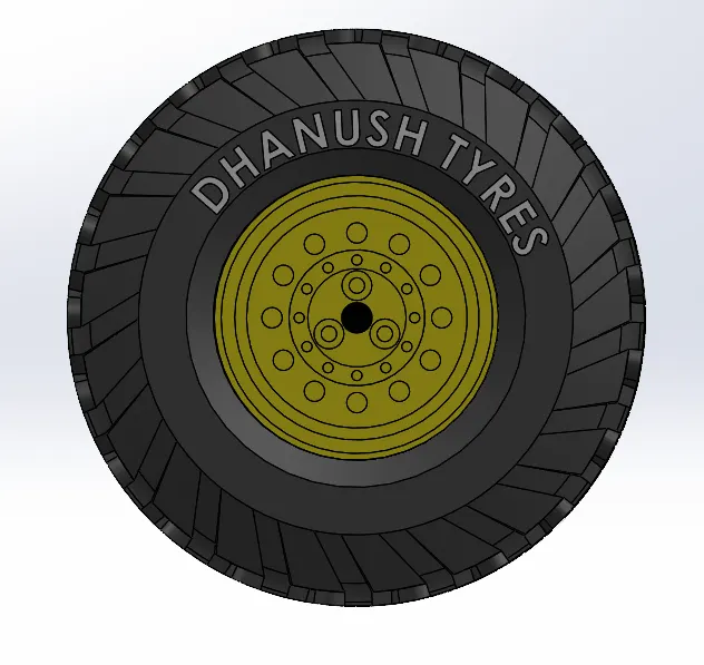
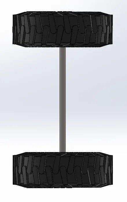
BACK VIEW TOP VIEW
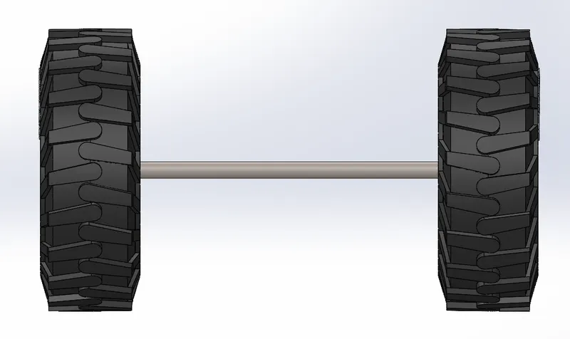
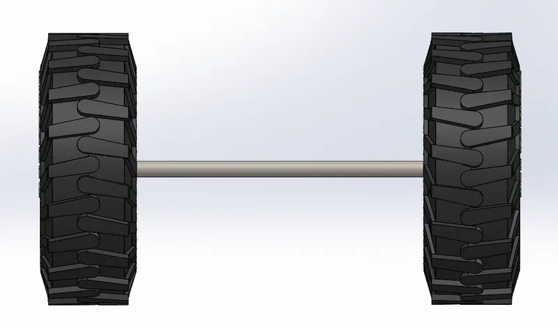
LEFT VIEW RIGHT VIEW
BOTTOM VIEW
5. Zip File of the axile rod, rim, Tyre of Front-End Loader: -
Link: - https://drive.google.com/file/d/1T0OTbZudP9o8rXKokYJsxXSkw4K73yzJ/view?usp=sharing
Assembly of Front-End Loader: -
1. The main purpose of the assembly of the Front-End Loader is that assembly all individual parts with suitable mates.
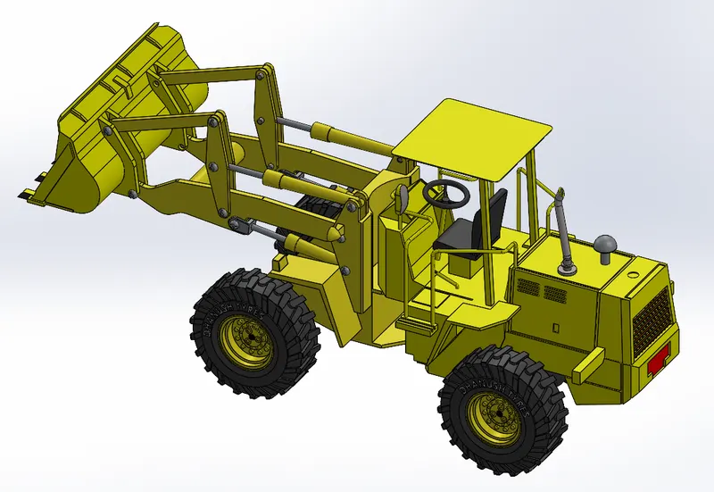
Trimetric View
2. Feature Manager Design Tree: -
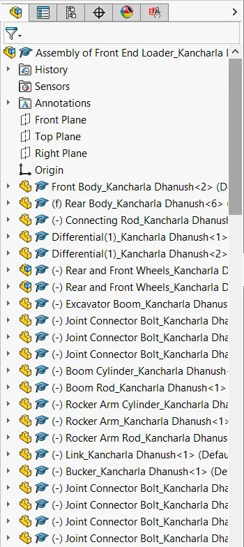
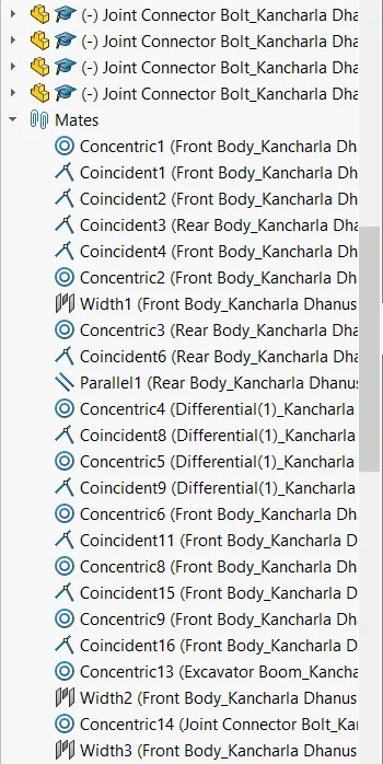
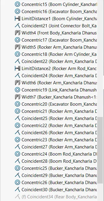
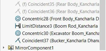
4. Presentations: -
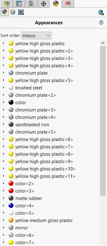
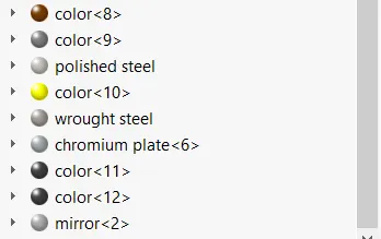
5. All Views of the Front-End Loader: -
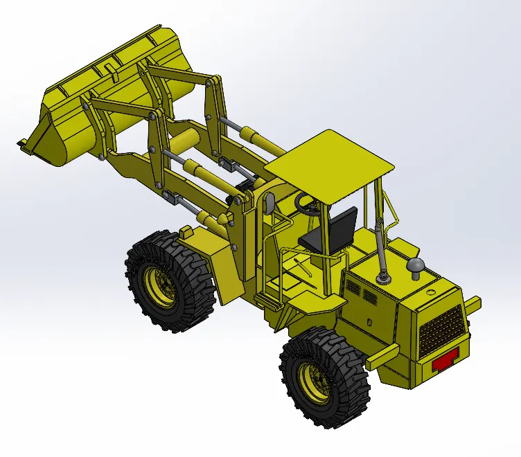
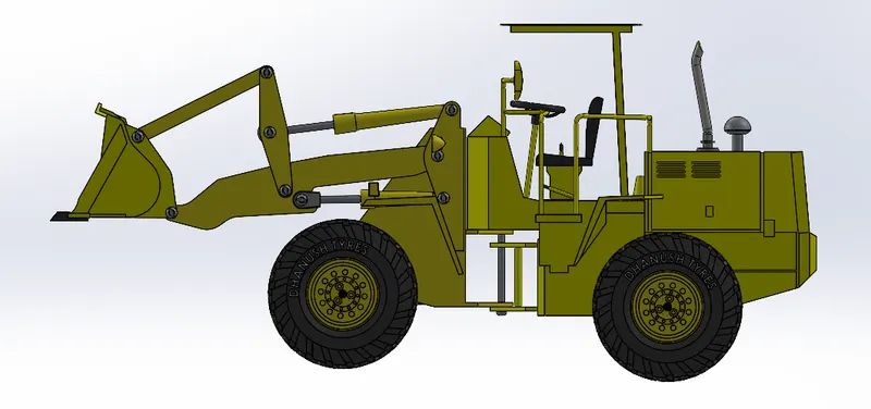
ISOMETRIC VIEW FRONT VIEW
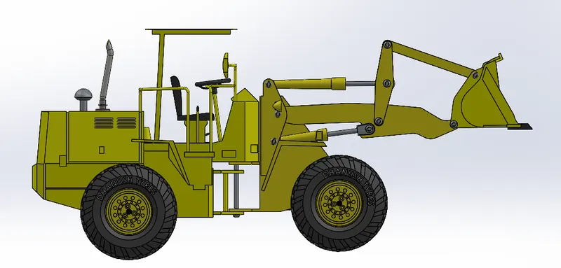
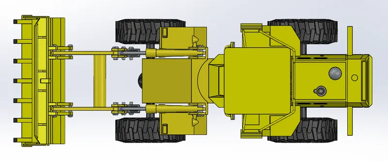
BACK VIEW TOP VIEW
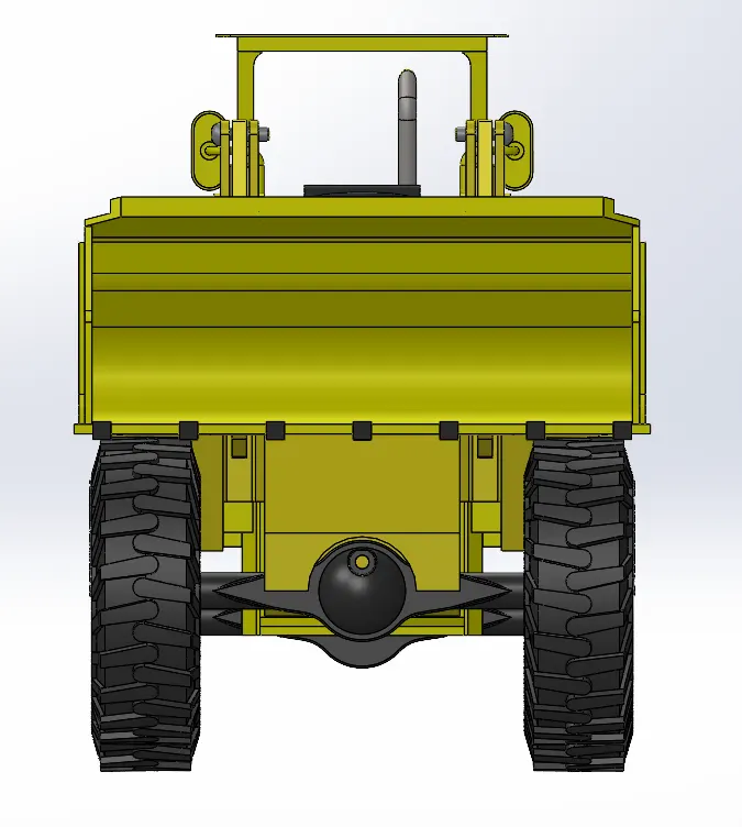
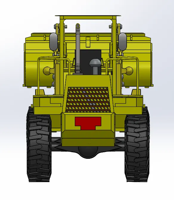
LEFT VIEW RIGHT VIEW
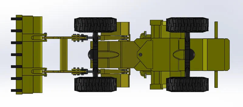
BOTTOM VIEW
Explanation of each component: -
The mates' feature is used to assemble the Front-End Loader. Each component has a defined relationship with either the base component or the other components. The following are some relationships that are utilized to couple the components of a Front-End Loader:
- Concentric
- Coincident
- Parallel
- Tangent
- Width
DECAL APPLICATION, CAMERA SET-UP, & SCENES: -
The oil tank, gas tank, and rear fender all have decals on them. For adding the decals, we can use projected and label in the mapping process.
The view tab is where the camera is added; the view tab also contains the light. Final rendering is helped by camera setup.
Sceneries: Appropriate scenes are added to the model to increase realism.
RENDERING: -
We used the Solid works Visualization tool to depict the helicopter. We used render tools in Solid works to render individual pieces.
Procedure: -
- Visualize by importing the assembly model.
- Modify the model's appearance however you like.
- The model should have scenes.
- The final rendering is completed when finished.
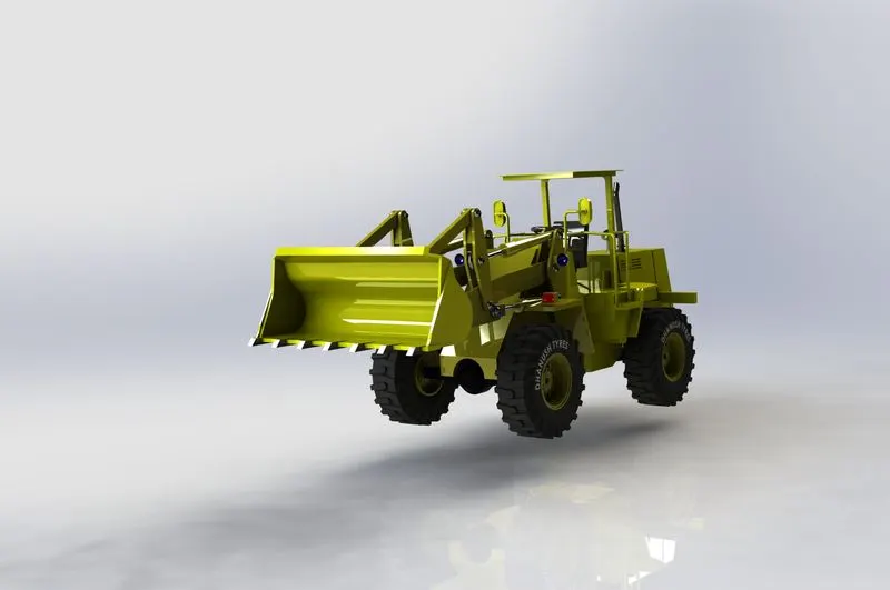
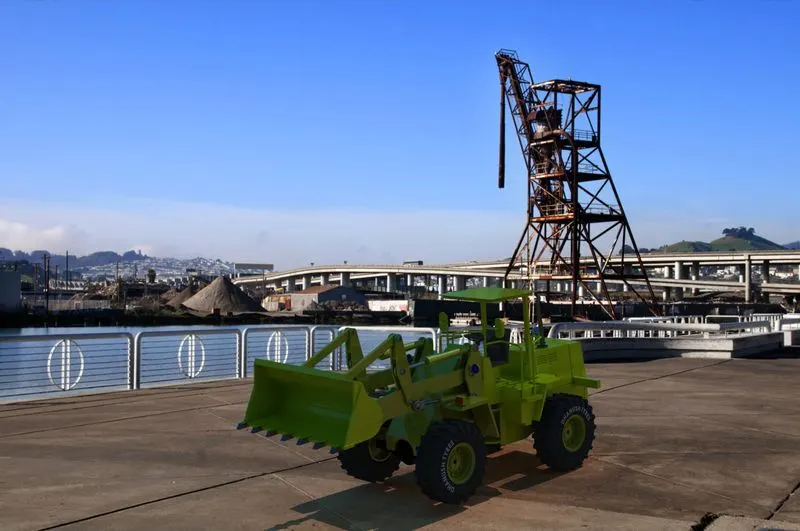
FINAL RENDERS OF THE FRONT-END LOADER: -
Conclusion:
- All the parts were designed in SolidWorks.
- The parts were assembled in the assembly.
- The assembled Front-End Loader was rendered using Photo view 360 as well as SolidWorks Visualize.