Modelling, assembly and rendering of Yatch
Title: Modelling, Assembly and Rendering of Yatch in solidworks
Objective: To recreate parts of Yatch, assembled them and creating photorealistic rendering of the Assembly.
Introduction: This report is about design and assembly of Sunseeker Yatch in solidworks and rendering the Yatch using photoview 360. Solidworks is a 3D CAD software using which i have modelled the different parts of the Yatch assembled them in proper manner, adjusted Yatch orientation to make it look like real world yatch, then using photoview 360 which is rendering software, I have render the images of Yatch in different views.
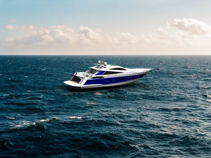
Design methodology: For assembly of yatch I have used Bottom up approach in which all the parts are prepare according to dimensions and then assembled.
Top down approach: In the top-down approach, an overview of the system is prepared without going into detail of any part of it. In this approach you start your work in the assembly and built parts to fit in the assembly. Geometry of one part is used to help define the other parts.
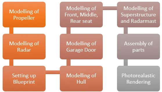
Description:
Sketch tools used in this project:
- Sketch: To create a new sketch or edit previous sketch.
- 3D Sketch: To create a new sketch in 3 dimensions.
- Smart Dimensions: Creates dimensions for selected one or more 2d or 3d sketch entities.
- Line, Circle, Spline, Rectangle, Arcs, Ellipse, Slots, Sketch fillet.
- Trim Entities: Used to trim extra sketch entity.
- Extend Entities: Used to extend sketch entity to meet another entity.
- Convert Entities: Converts selected edges and sketch entities into identical entities on sketch plane.
- Offset Entities: Offsets the selected sketch entities by specified distance.
- Mirror Entities: Mirrors the selected sketch entities about centerline or plane reference.
- Linear pattern: This tool patterns the selected sketch in one or two linear direction.
- Circular Pattern: This tool patterns the sketch entities in circular instances.
- Dynamic Mirror: This tool creates sketch entities that are mirror about selected entity as you draw them.
Features used in this Project:
- Extrude Boss/Base: This feature extrudes the selected sketch in one or two directions and creates a solid Feature.
- Revolve Boss/Base: This feature revolves the selected sketch around the selected axis to create a solid feature.
- Sweep Boss/Base: This feature sweep the close profile along the path that is open or close to create solid feature.
- Lofted Boss/Base: This feature is used to add material between two or more profile to create a solid feature.
- Extrude Cut: This feature cuts the solid model by extruding the sketch in one or two direction.
- Revolve Cut: This feature cuts the solid model by revolving the sketch around the selected axis.
- Sweep Cut: This feature cuts a solid model by sweeping close profile along the selected path that is open or close.
- Fillet: This feature creates rounded internal or external face along one or more edges on solid or surface feature.
- Chamfer: This feature creates a beveled feature on selected edges, faces on solid model.
- Linear Pattern: This feature patterns features, body or faces in ore two linear direction.
- Circular Pattern: This Feature patterns feature, face or body in number of instances around the selected axis.
- Mirror: This feature is use to mirror body, faces or feature about the selected plane or geometry.
- Shell: This feature is use to create hollow bodies from solid bodies by specifying the thickness of wall.
- Reference Geometry: This feature is used to create reference point, plane, coordinate system and axis by selection of different plane, points, lines, distance etc.
- Project Curve: This feature is used to create curve in 3D using two curves in different planes.
- Composite Curve: this feature combines selected edges, points and sketches into a single curve.
- Dome: This feature creates dome on selected face.
- Split: This feature creates multiple bodies from single body. The sketch is not required to be closed profile.
- Combine: This feature is used to create single solid body from two or more bodies.
- Move/Copy Bodies: This feature moves, copy, rotates solid or surface bodies.
Surface tools used in project:
- Surface Trim: Trims a surface when it intersects with another surface, plane or sketch.
- Boundary surface: Creates a surface between profiles that can be tangent or curvature that is continuous in all directions.
- Swept surface: Creates a surface by sweeping sketch along the guide curve.
- Surface loft: Creates a lofted surface between two profiles or sketches.
- Surface knit: Creates two or more adjacent surfaces into single surface.
- Extrude Surface: Extrude a sketch in one or two direction to create a surface feature.
- Filled surface: patches a surface within boundary defined by edges, sketches or curve.
- Offset surface: Creates an offset surface using gaps.
- Ruled surface: Inserts ruled surfaces in a specified directions from edges.
- Delete faces: Delete faces from surface bodies or solid body.
- Extend Surface: Extend one or more edges or faces on surface, based on end conditions and extension type.
Parts:
1) Propeller: a mechanical device for propelling a boat consisting of a revolving shaft with two or more broad, angled blades attached to it. There are 3 propeller in our yatch.
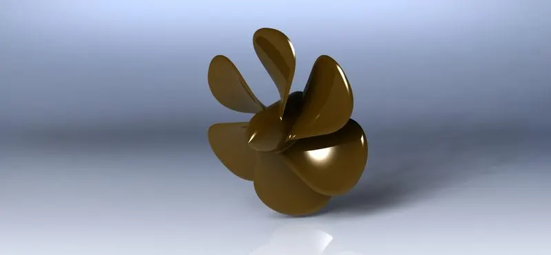
Sketch tools used: line, spline, rectangle, Circle
Features used: Revolve, Loft, Cut extrude, Circular pattern, fillet
2) Radar: It is a precious navigation aid, especially in situations of reduced visibility. It can be used to know the position and distance of other boats, other obstructions such as rocks and buoys and the coast.
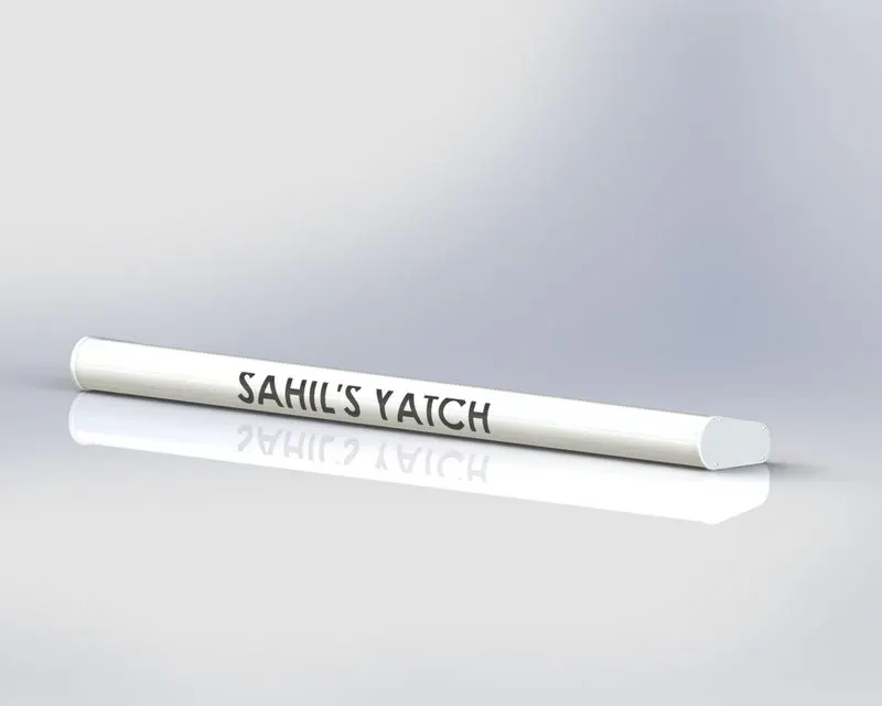
Sketch tools used: Line, Circle, Offset entities, Polygon, Text
Features used: Extruded Boss/Base, Cut extrude, Sketch Pattern, Split Line, Fillet, Mirror
3) Blueprint Setup: A blueprint is a reproduction of a technical drawing, documenting an architecture or an engineering design, using a contact print process on light-sensitive sheets.
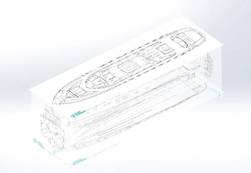
Tools>Sketch tools> sketch picture feature is used to setup blueprints in different views. Also reference planes are used create additional planes.
4) Hull: The hull of a ship is the most notable structural entity of the ship. It can be defined by that it is the watertight enclosure of the ship, which protects the cargo, machinery, and accommodation spaces of the ship from the weather, flooding, and structural damage. A hull is the watertight body of a ship, boat, or flying boat. The hull may open at the top or it may be fully or partially covered with a deck.
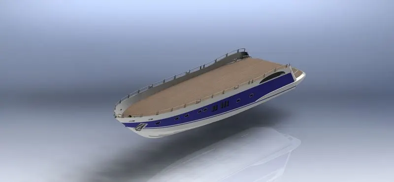
Sketch tools used: Line, Spline, Circle, Rectangle, Arc, Slot, 3-D Sketch, Sketch picture, convert entities, offset entities, trim entities, extend entities, mirror entities, linear sketch pattern
Features used: Extruded boss, revolve, loft, sweep, cut extrude, shell, fillet, chamfer, dome, reference plane, project curve, split line, linear pattern, combine and mirror.
Surface features used: surface loft, surface extrude, surface trim, surface fill, surface knit
5) Garage door: Garage door is mounted on backside of yatch. It is big enough to accommodate the automobile vehicle through it.
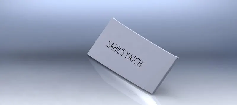
Sketch tools used: Line, circle, text
Features used: cut extrude, shell, fillet, mirror, reference plane.
6) Front seat: It is used for sitting purpose. It is located at front of yatch.
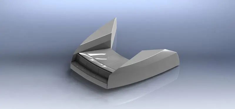
Sketch tools used: line, spline, circle, arcs, rectangle, convert entities, offset entities
Features used: cut extrude, chamfer, fillet, revolve, mirror, dome.
Surface features used: sweep surface, extrude surface, trim surface, fill surface, loft surface, knit surface
7) Middle seat: It is used for sitting purpose. It is located at middle portion of yatch.
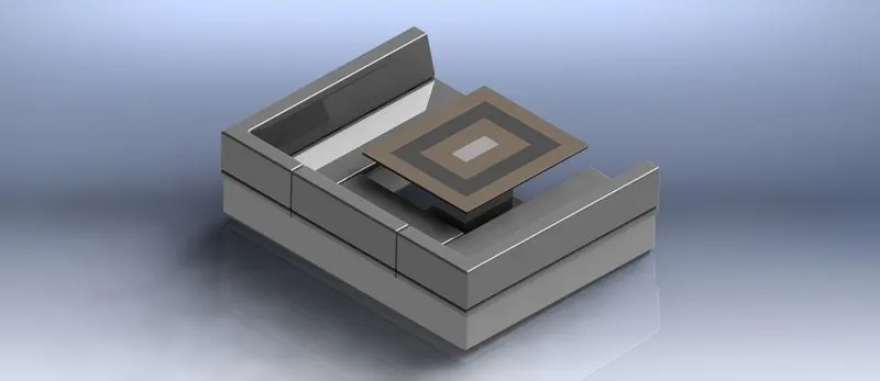
Sketch tools used: line, spline, arcs, rectangle, convert entities, offset entities
Features used: cut extrude, chamfer, fillet, mirror, dome.
8) Rear seat: It is used for sitting purpose. It is located at back portion of yatch.
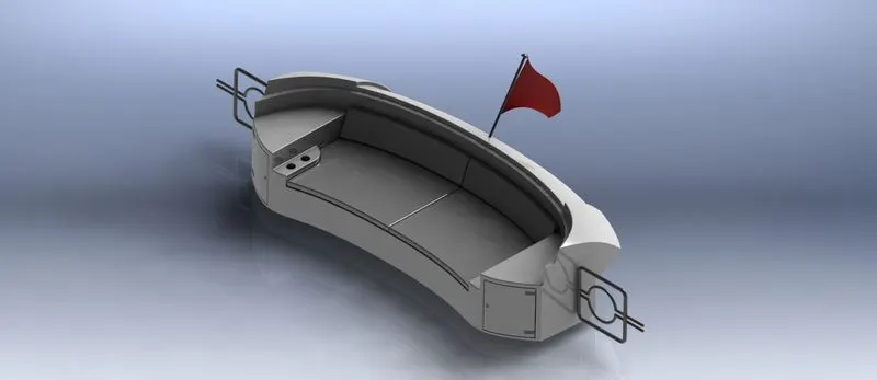
Sketch tools used: line, spline, circle, arcs, rectangle, convert entities, offset entities, 3D sketch
Features used: cut extrude, chamfer, fillet, mirror, dome, revolve, sweep boss,
Surface features used: surface offset, sweep surface, extrude surface, trim surface, fill surface, loft surface, knit surface, ruled surface, loft surface, surface extend
9) Superstructure: A superstructure is an extended construction of any building or platform that rises above the rest of the building or platform in a distinct manner. In ships this is the name given to the part of the ship that emerges from the deck. However any mast, sails, any armaments or arsenal are not included in this category.
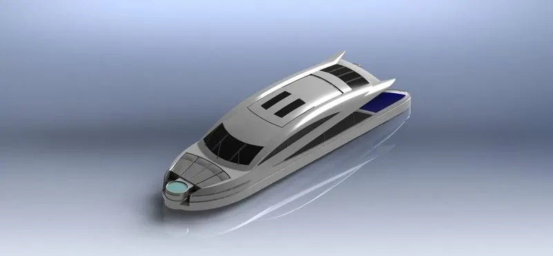
Sketch tools used: line, spline, circle, arcs, rectangle, convert entities, offset entities, 3D sketch, trim entities, extend entities
Features used: cut extrude, chamfer, fillet, revolve, mirror, dome, sweep boss, split line, project curve
Surface features used: surface offset, sweep surface, extrude surface, trim surface, fill surface, loft surface, knit surface, ruled surface, loft surface, surface extend
10) Radar mast: They are electronic navigation instruments that use a rotating antenna to sweep a narrow beam of microwaves around the water surface surrounding the ship to the horizon, detecting targets by microwaves reflected from them, generating a picture of the ship's surroundings on a display screen. It is mounted on top of superstructure.
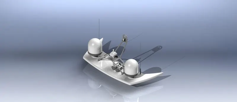
Sketch tools used: line, spline, circle, arcs, rectangle, convert entities, offset entities, 3D sketch, trim entities, extend entities
Features used: cut extrude, chamfer, fillet, mirror, dome, revolve, sweep boss, split line, project curve, shell, and combine
Assembly
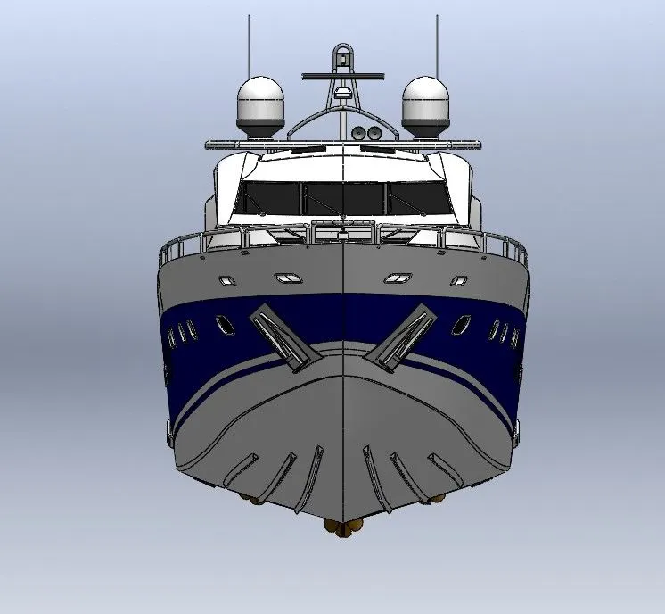
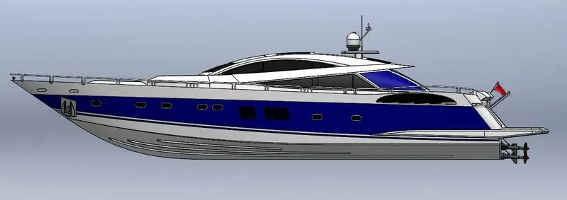
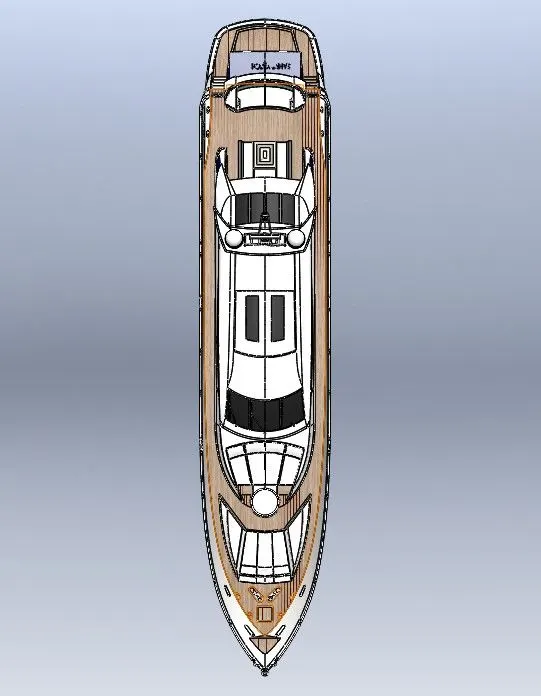
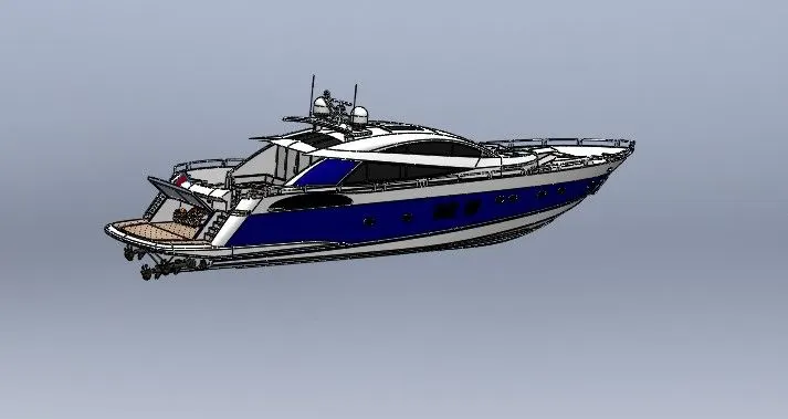
For assembly of Yatch we have fix Hull as reference for all other parts. In the following order we have assembled all the parts with given mates.
Assembly images:
1)Front view
2) Side view
3) Top view
4) Camera view
5)Isometric view
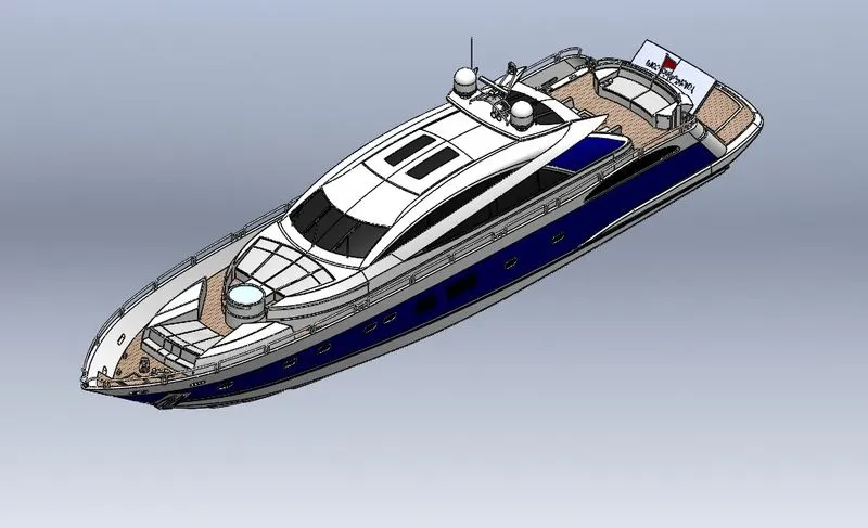
Features that are used for assembly of Yatch : Insert parts, Mates
Mates:
Creates geometric relationships between assembly components to define the allowable direction of linear or rotational movement of components. We can move a component within its degrees of freedom to visualize the assembly's behavior.
|
Sr.no |
Part |
Mates |
|
1 |
Hull |
Fix |
|
2 |
Superstructure |
Coincident, Distance |
|
3 |
Radarmast |
Distance, coincident |
|
4 |
Front seat |
Coincident, Distance |
|
5 |
Middle seat |
Coincident, Distance |
|
6 |
Rear seat |
Coincident, Distance |
|
7 |
Garage door |
Cocentric, Coincident, Limit angle |
|
8 |
Propeller |
Coincident, coincident |
|
9 |
Radar |
Coincident, coincident |
|
10 |
Chopper bike |
Coincident, fix |
Rendering
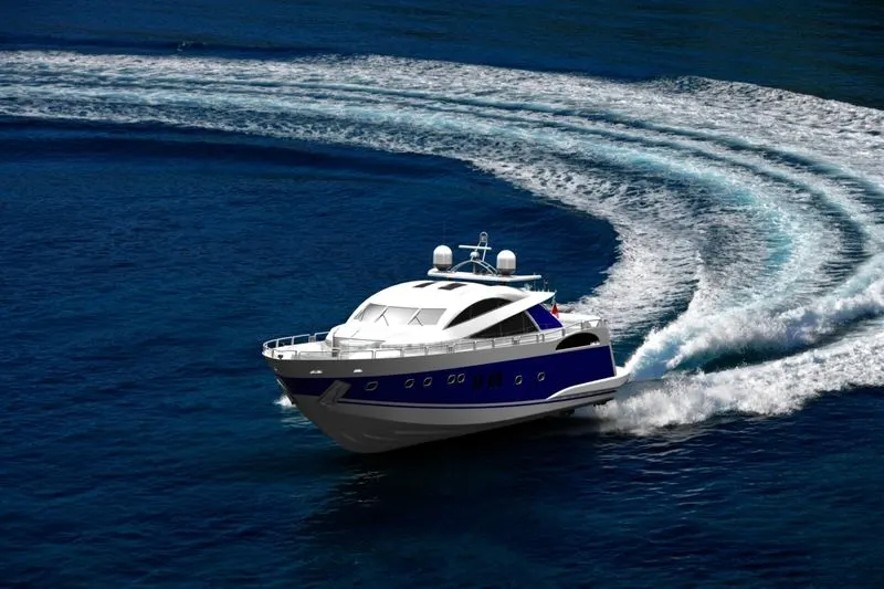
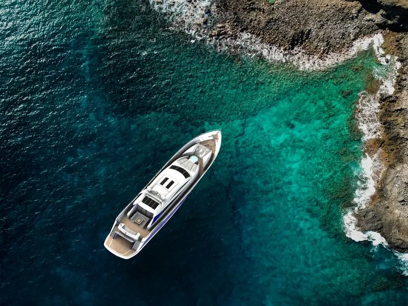
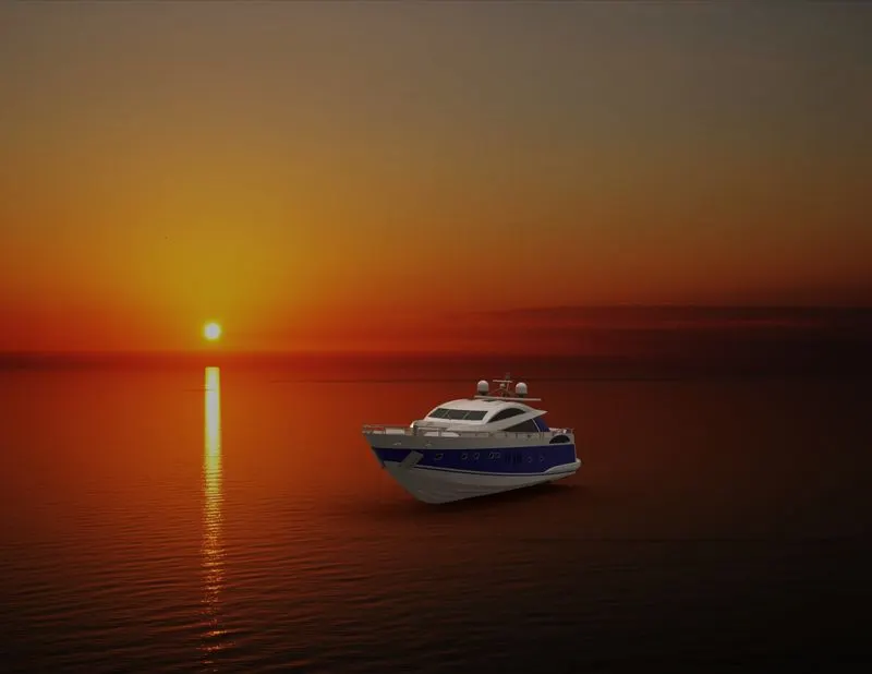
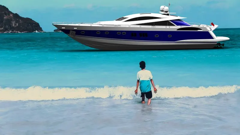
Before rendering of model we have done some preprocessing. This includes applying decals to hull deck surface, stairs etc . After preprocessing we have done camera setup, background and environment conditions, and lights position adjustments. Then using photoview 360 we have done final rendering.
Rendered Images:
Conclusion
- All parts of Yatch are successfully modeled and appropriate appearances are given to each parts.
- The assembly of the parts are done rightly with proper mates and constrains.
- Preprocessing, Camera setup, Light setup, Background and environment setup is done properly.
- Successfully rendered images of Predator using photoview 360.
NOTE: Solidworks visualize is not working in my computer so I have uploaded images rendered in photoview 360.