Boeing-747 _ Final_Project of Boeing
1) Title: Design of Boeing 747 airplane
2) Objective: The objective of this project is to model and assemble Boeing 747-8 aircraft using Solidworks and Rendering of plane in photoview 360.
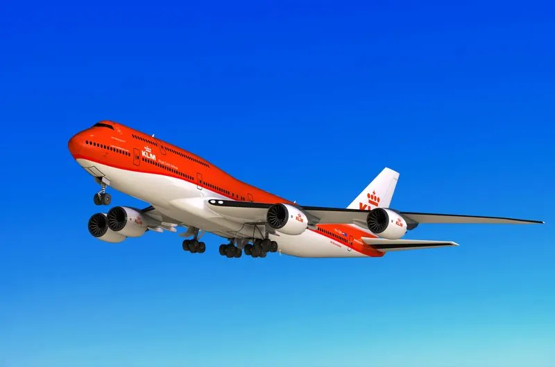
3) Introduction: The Boeing 747 is a large, long-range wide-body airliner designed and manufactured by Boeing Commercial Airplanes in the United States. The 747 was the first airplane dubbed "Jumbo Jet", the first wide-body airliner.
The 747 is a four-engine jet aircraft, initially powered by Pratt & Whitney JT9D turbofan engines, then General Electric CF6 and Rolls-Royce RB211 engines for the original variants.
Boeing introduced the -200 in 1971, with more powerful engines for a heavier maximum take-off weight (MTOW) of 833,000 pounds (378 t) from the initial 735,000 pounds (333 t), increasing the maximum range from 4,620 to 6,560 nautical miles (8,560 to 12,150 km).
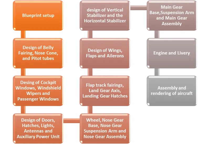
Different parts modelled in this project are:
1) Fuselage
2) Belly Fairing
3) Nose Cone
4) Pitot Tubes
5) Cockpit Windows
6) Windshield Wipers
7) Passenger Windows
8) Doors & Hatches
9) Lights & Antennas
10) Auxiliary Power Unit (APU)
11) Horizontal Stabilizer
12) Vertical Stabilizer
13) Static Discharge Tubes
14) Wings
15) Flaps & Ailerons
16) Flap Track Fairings
17) Landing Gear Axis
18) Landing Gear Hatches Open
19) Landing Gear Hatches Closed
21) Wheel
22) Nose Gear Base
23) Nose Gear Suspension Arm
24) Main Gear Base
25) Main Gear Suspension Arm
26) Engine
27) Livery
4)Design methodology: For assembly of Boeing 747 I have used Bottom up approach in which all the parts are prepare according to dimensions and then assembled.
Other approach can be used is Top down approach: In the top-down approach, an overview of the system is prepared without going into detail of any part of it. In this approach you start your work in the assembly and built parts to fit in the assembly. Geometry of one part is used to help define the other parts.
5) Description:
Sketch tools used in this project:
- Sketch: To create a new sketch or edit previous sketch.
- 3D Sketch: To create a new sketch in 3 dimensions.
- Smart Dimensions: Creates dimensions for selected one or more 2d or 3d sketch entities.
- Line, Circle, Spline, Rectangle, Arcs, Ellipse, Slots, Sketch fillet.
- Trim Entities: Used to trim extra sketch entity.
- Extend Entities: Used to extend sketch entity to meet another entity.
- Convert Entities: Converts selected edges and sketch entities into identical entities on sketch plane.
- Offset Entities: Offsets the selected sketch entities by specified distance.
- Mirror Entities: Mirrors the selected sketch entities about centerline or plane reference.
- Linear pattern: This tool patterns the selected sketch in one or two linear direction.
- Circular Pattern: This tool patterns the sketch entities in circular instances.
- Dynamic Mirror: This tool creates sketch entities that are mirror about selected entity as you draw them.
Features used in this Project
- Extrude Boss/Base: This feature extrudes the selected sketch in one or two directions and creates a solid Feature.
- Revolve Boss/Base: This feature revolves the selected sketch around the selected axis to create a solid feature.
- Sweep Boss/Base: This feature sweep the close profile along the path that is open or close to create solid feature.
- Lofted Boss/Base: This feature is used to add material between two or more profile to create a solid feature.
- Extrude Cut: This feature cuts the solid model by extruding the sketch in one or two direction.
- Revolve Cut: This feature cuts the solid model by revolving the sketch around the selected axis.
- Sweep Cut: This feature cuts a solid model by sweeping close profile along the selected path that is open or close.
- Fillet: This feature creates rounded internal or external face along one or more edges on solid or surface feature.
- Chamfer: This feature creates a beveled feature on selected edges, faces on solid model.
- Linear Pattern: This feature patterns features, body or faces in ore two linear direction.
- Circular Pattern: This Feature patterns feature, face or body in number of instances around the selected axis.
- Mirror: This feature is use to mirror body, faces or feature about the selected plane or geometry.
- Shell: This feature is use to create hollow bodies from solid bodies by specifying the thickness of wall.
- Reference Geometry: This feature is used to create reference point, plane, coordinate system and axis by selection of different plane, points, lines, distance etc.
- Project Curve: This feature is used to create curve in 3D using two curves in different planes.
- Composite Curve: this feature combines selected edges, points and sketches into a single curve.
- Dome: This feature creates dome on selected face.
- Split: This feature creates multiple bodies from single body. The sketch is not required to be closed profile.
- Combine: This feature is used to create single solid body from two or more bodies.
- Move/Copy Bodies: This feature moves, copy, rotates solid or surface bodies.
Surface tools used in project
- Surface Trim: Trims a surface when it intersects with another surface, plane or sketch.
- Boundary surface: Creates a surface between profiles that can be tangent or curvature that is continuous in all directions.
- Swept surface: Creates a surface by sweeping sketch along the guide curve.
- Surface loft: Creates a lofted surface between two profiles or sketches.
- Offset surface: Creates an offset surface using gaps.
- Ruled surface: Inserts ruled surfaces in a specified directions from edges.
- Delete faces: Delete faces from surface bodies or solid body.
Parts:
1) Blueprint setup:
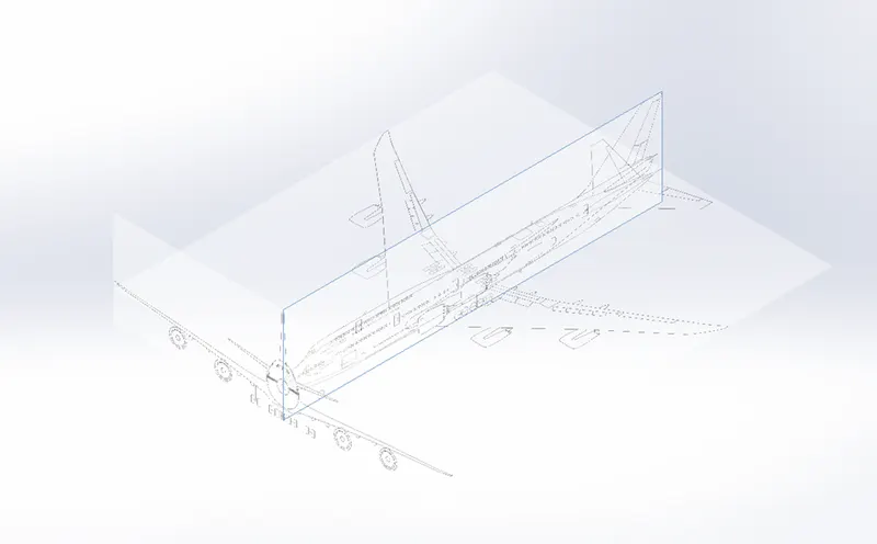
First of all blueprints are downloaded from site. Then blueprint size is change according to actual size of plane to make the model 1:1 with actual plane. Front, Side and Top blueprints are setup with the nose of plane as origin point. The transparency of blueprints is kept at 0.75-0.8.
2) Fuselage:
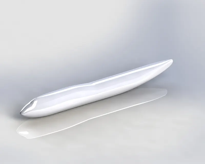
The fuselage is an aircraft's main body section. It holds crew, passengers, or cargo. First of all using the side blueprint, outer line of fuselage is drawn on side plane. Then projected curve is drawn using two sketches from top plane and side plane. This curve will be used as guide curve for lofted surface. After that reference planes are created which are parallel to front plane and constrain by points on side profile sketch. Then profile is drawn on each plane using splines which are constrain by pierce relations. After completion of all profiles, lofted surface is created. Side profile sketch and projected curve is used as guide curve. Using mirror feature lofted surface is mirror using side plane as mirror plane. Then using thicken feature the surface body is converted into solid body.
3) Belly Fairing:
Also called a "ventral fairing", it is located on the underside of the fuselage between the main wings. It can also cover additional cargo storage or fuel tanks.
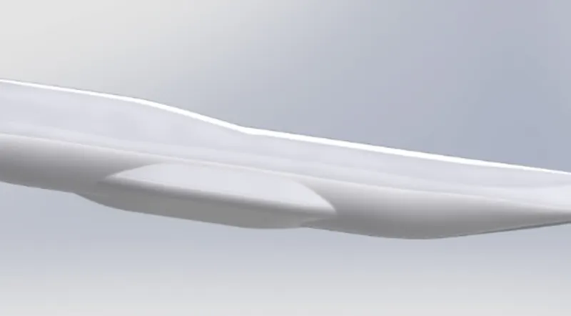
For the making of belly fairing, basic shape is extruded from right plane. Then using split command extra part is removed. After that some fillets are given to smoothen the edges. Then using mirror tool half belly fairing is mirrored along the right plane. Combine tool is used to make single body from two bodies i.e. fuselage and belly fairing.
4) Nose Cone:
A nose cone is the conically shaped forward most section of aircraft, designed to modulate oncoming airflow behaviors and minimize aerodynamic drag. On airliners the nose cone is also a dome protecting the weather radar from aerodynamic forces.
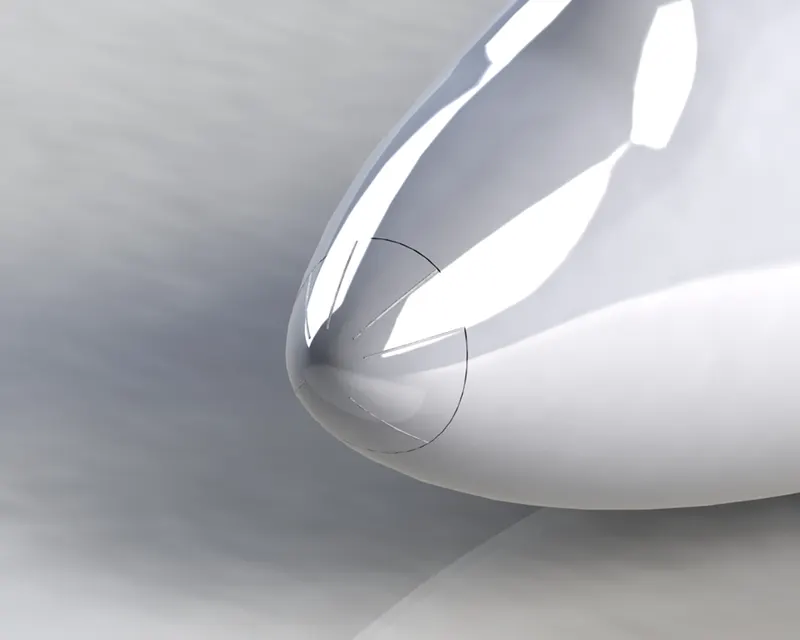 First of all using 3 vertical lines on right plane, the nose surface is divided into 8 parts using split line tool. Then using sketch on front plane 3 lines and one circle are projected on nose surface using split line tool. After that using sweep boss circular profiles are swept upon the projected lines. Fillets are given to edges of sweep boss. Finally mirror feature is used to mirror the features w.r.t. right plane.
5) Pitot Tubes:
Pitot tubes are flow measurement device used to measure fluid flow velocity. It is used to determine the airspeed of an aircraft. It is very important device of the aircraft.
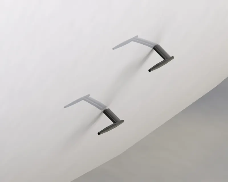
There are total 4 pitot tubes on Boeing 747. Features used to model the pitot tubes are- Boss Extrude,
Sweep Boss, Chamfer, Fillet, Cut Extrude, Reference plane, Axis.
6) Cockpit windows:
Cockpit windows provides visibility of front for pilots and protects them from high velocity air. Cockpits windows can be opened when the aircraft is on the ground. Cockpit windows in large aircraft have an anti-reflective coating, and an internal heating element to melt Frost and remove Fogg.
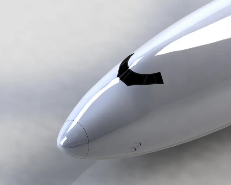
For making windows, sketches are projected on main body surface using split line tool. Then using offset entities those curves are offset to make the Frame for windows. Then using surface offset command frame surface is offset by 0 cm and thicken in order to make a separate body. Then fillets are given to frame. After that appearances are given to windows and frame.
7) Windshield wipers:
Windshield wipers are used to clean cockpit windows and remove any dust, snow or other things. Also windshield sprayer is used to improve the function of wipers in dry/wet conditions.
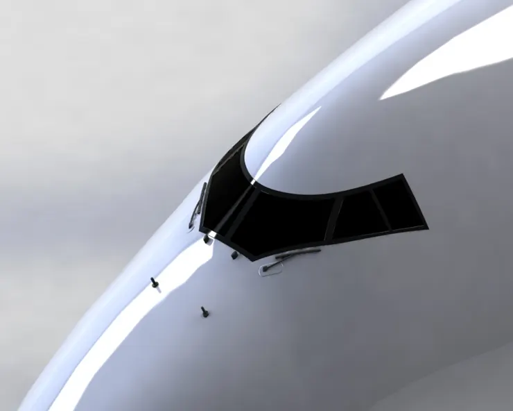
Features used to create wiper, sprayer and antenna are: Boss Extrude, Fillet, Project Curve, Sweep, 3D sketch, Move/Copy Bodies, Combine, Mirror.
8) Passenger Windows:
There are 250 passenger windows on this Boeing 747. Window is consisting of glass with metal frame at edges.
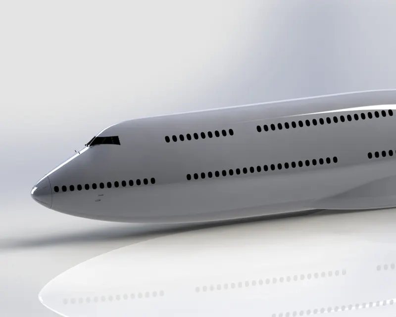
To create passenger window, a sketch block is made. Then using linear sketch pattern this sketch block is pattern. Using this created sketch window shapes are cut on fuselage surface using split line tool. Then appearances are given to windows and metal frame.
9) Doors & Hatches:
There are 6 doors on each side of aircraft. Cockpit hatch is above the cockpit. On the right side of fuselage, there are 3 hatches present.
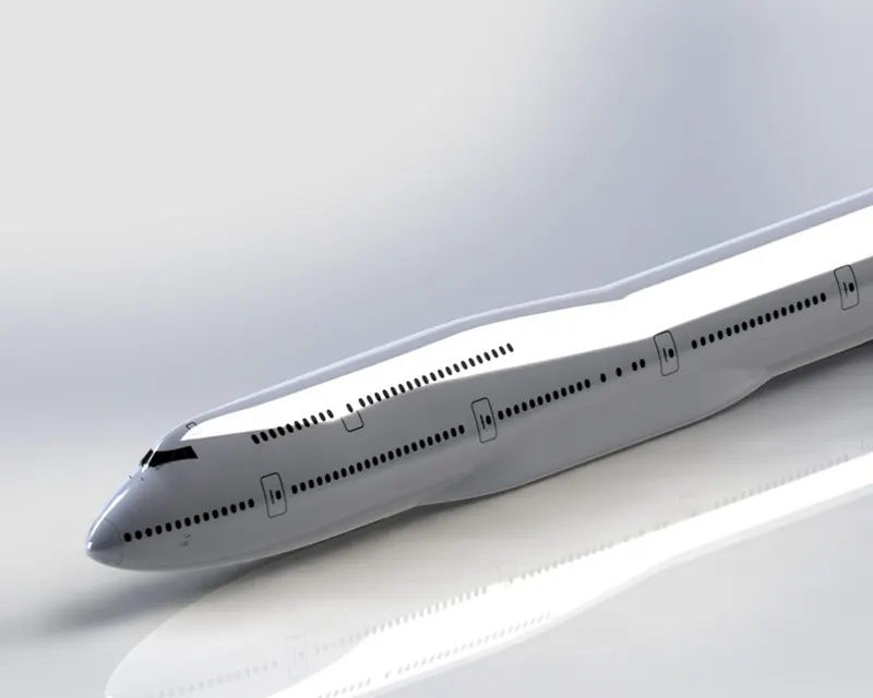
To create doors, a sketch block of door is made and then it is projected on fuselage body using split line tool. Then Split line tool is patterned using linear pattern tool. Similarly hatches on right side of plane and above the cockpit are made using split line tool. Outer surface of hatches and doors are offset using offset surface. This offset surfaces are then given thickness using Thicken tool.
10) Lights and Antennas:
There are 2 red lights, 3 wing antennas and 2 slot shape antennas on the plane.
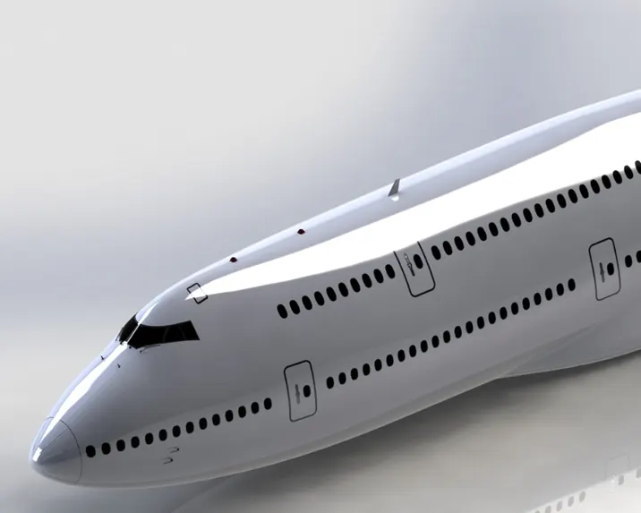
Features used to create lights and antennas are: Revolve Boss, Split, Move/Copy body, Boss Extrude, Draft, Offset surface, Thicken, Fillet.
11) Auxiliary Power Unit:
An Auxiliary Power Unit or APU allows an aircraft to operate autonomously without reliance on ground support equipment such as a ground power unit, an external air-conditioning unit or a high pressure air start cart.
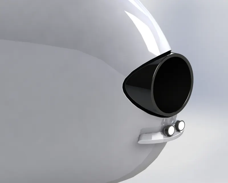
Extrude cut is used to cut a hole in backside of fuselage. Then extrude boss feature is used to create hollow cylindrical exhaust. Fillets are applied to cylinder edges. Using split line tool a slot is projected on fuselage surface. Using Thicken feature this surface is drafted out. To create lights at back following feature are use: Extrude boss, extrude cut, Fillets. Lastly appearances are given.
12) Vertical Stabilizer: The stabilizer is a fixed wing section whose job is to provide stability for the aircraft, to keep it flying straight. The vertical stabilizer prevents side-to-side, or yawing, motion of the aircraft nose.
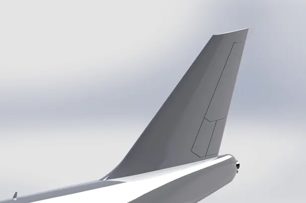
Main Shape of stabilizer is made using Loft. (Two profiles and guide curves) Then using extrude cut, Radar and other parts are separated from main body of stabilizer. Then using extrude boss, discharge tubes are made. Fillets are provided to edges.
13) Horizontal Stabilizer: The horizontal stabilizer prevents up-and-down, or pitching, motion of the aircraft nose.
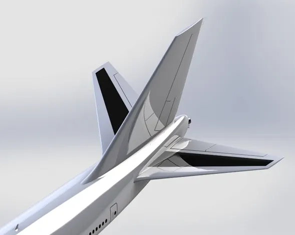
Using projected curve, outlines of horizontal stabilizer are drawn. Then lofted boss is made using two sketches are profile and projected curves as guidelines. Then using extrude cut, Radar and other parts are separated from main body of stabilizer. Then using extrude boss, discharge tubes are made. Fillets are provided to edges.
14) Wing: A wing is a type of fin that produces lift while moving through air. Wings have streamlined cross-sections that are subject to aerodynamic forces and act as airfoils.
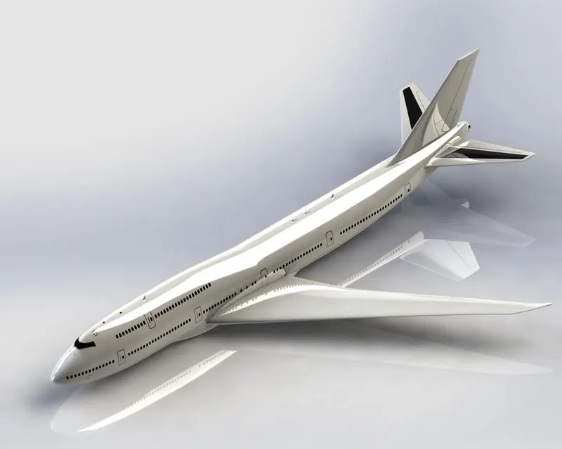
Two guide curves are created using projected curve feature for front side and back side. Then reference planes are created to draw wing profiles. Then using wing profiles and guide curves Lofted boss is created. Then Variable fillet is applied on wing. Offset surface is used to copy fuselage surface. Using newly created surface, wing is separated from fuselage body using cut with surface feature. Then extra surface is removed using delete/keep body feature.
15) Flaps and Ailerons: Flaps are retractable ‘extensions’ of the wing, that change the angle of the airfoil, allowing for a slower stall speed.An aileron is a hinged flight control surface usually forming part of the trailing edge of each wing of a fixed-wing aircraft. Ailerons are used in pairs to control the aircraft in which normally results in a change in flight path due to the tilting of the lift vector.
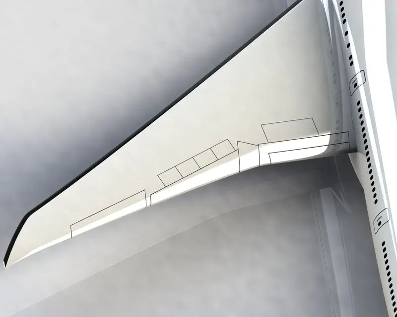
Using Thin Extrude cut Flaps and Ailerons are separated from wing. Then using Split line feature Spoiler lines are projected on wing. Offset surface feature is used to copy all newly created surfaces. Then using Thicken feature, copied surfaces are given Thickness. Fillets are provided on edges. Then using Split line feature lights are Front of wings are projected on wing surfaces.
16) Flap Tack Fairing: A flap track fairing is a secondary structure whose function is to provide an aerodynamic cover and so reduce drag.
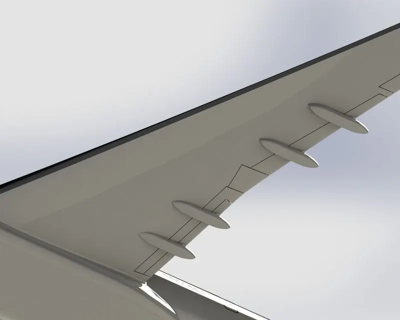
Boss Extrude is used to make basic shape of fairing. Then using split tool Extra portion is trimmed. Fillets are provided on edges. Move/Copy Body feature is used to move fairing on their positions. Then all fairings are mirrored on other side of planes along with wings. Combine feature is used to combine Wings with main body.
17) Landing Gear Hatches: Landing gear Hatches are door that opens only when plane is landing and when it is on ground. It increases aerodynamics of plane and it hides the wheel inside plane body.
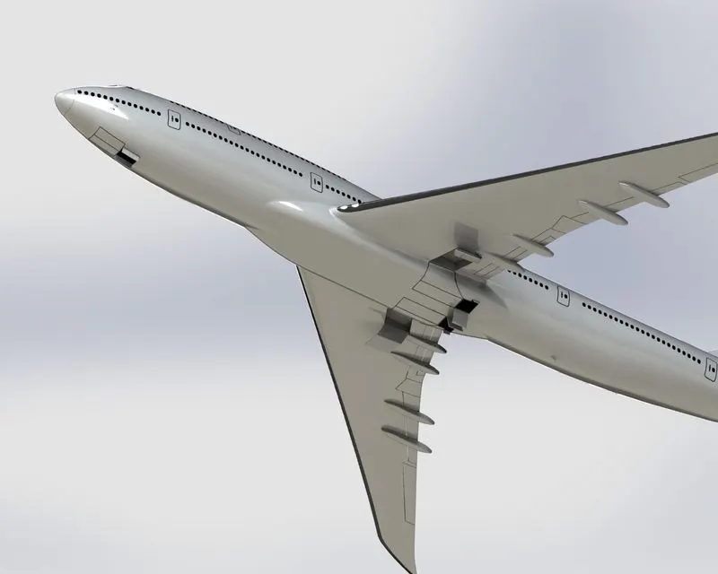
Features used: Split line, Surface offset, Thicken Fillet, Mirror, Cut extrude, Reference plane, Sweep boss, Extrude Boss,
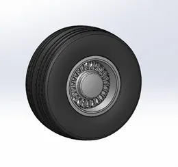
18) Nose Gear Assembly: The nose wheel assembly is located under the nose of the aircraft and is the third wheel of the landing gear system. The nose wheel design consists of two halves bolted together with a tire mounted and ultimately mounted to the nose gear fork. First of all nose gear base is modelled then wheels and Suspension arms are assembled.
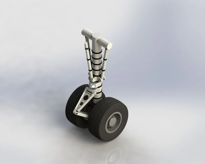
Wheels: Wheels are made of 3 things namely Tire, Rim, and Bolt Heads. First of all revolve boss is used to make basic shape of tire. Then using revolve cut feature, tire threads are formed. Then fillets are
provided on edges and at last the tire is made hollow from inside using shell feature.
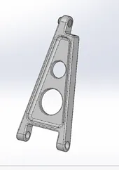
Suspension Arm: Feature used: Boss extrude, cut extrude, Fillet, Mirror.
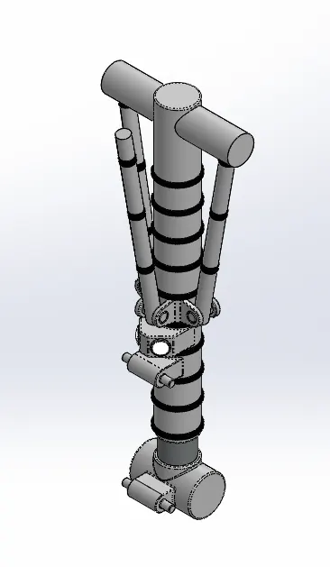
Nose Gear Base: Features used: Boss extrude, cut extrude, Fillet, Mirror, Linear pattern, Combined, circular Pattern, Chamfer, Split line, Sweep, Move/copy bodies, Dome.
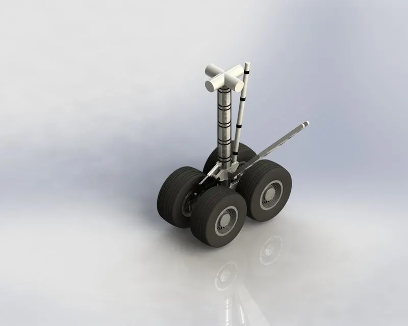
19) Main Gear Assembly: Main landing gear assembly consist of wheels, Main gear base and suspension arms. It has 4 wheels attach. Approach for main gear assembly is same as nose gear assembly. Same
feature are used to model and assemble mean gear.
20) Engine: An aircraft engine, often referred to as an aero engine, is the power component of an aircraft propulsion system. The boeing 747 has 4 turbojet engines.
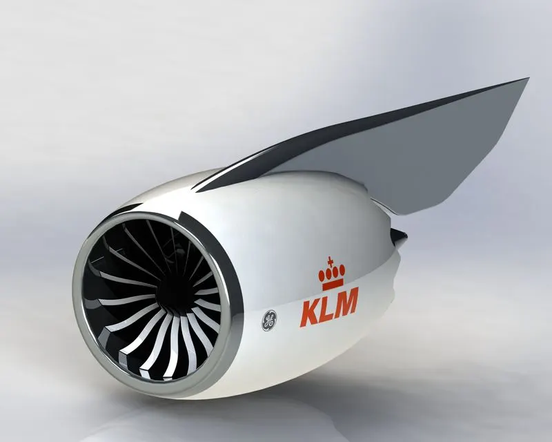
Features used: Basic outer shape of engine is made using revolve boss. Then using extrude cut front portion of engine is cut. Split tool is used to remove front portion of engine at an angle. After providing fillets, revolved body is made hollow using shell tool. Split line tool is used to make front area of engine.
Other feature used to make engine are: Cut extrude, Circular pattern, Reference plane, Surface loft, Surface trim, Chamfer, Thicken, Surface revolve, Draft, Combine.
Assembly:
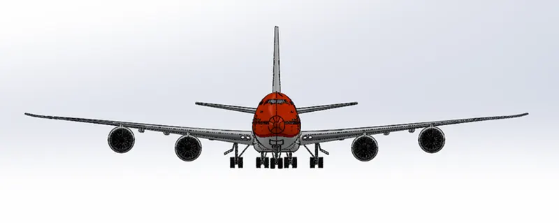
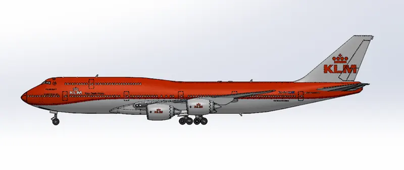
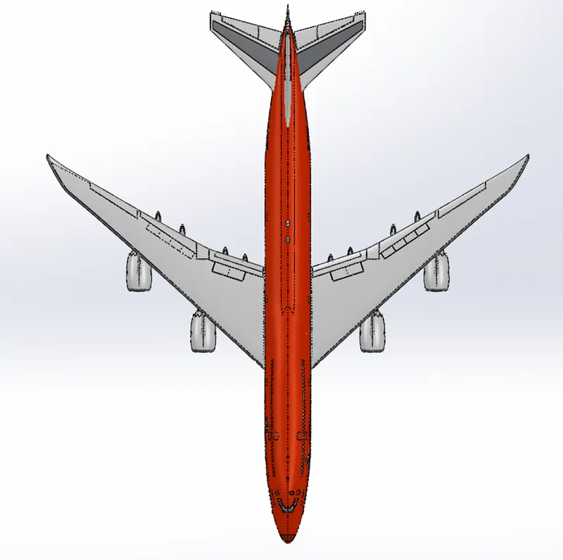
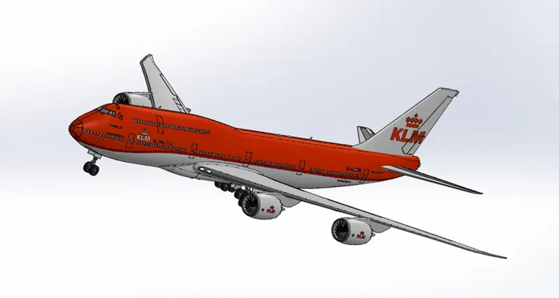
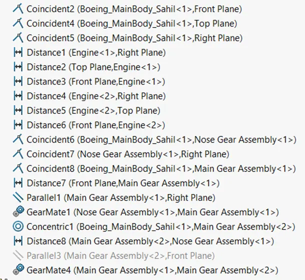
Mates:
Creates geometric relationships between assembly components to define the allowable direction of linear or rotational movement of components. We can move a component within its degrees of freedom to visualize the assembly's behavior.
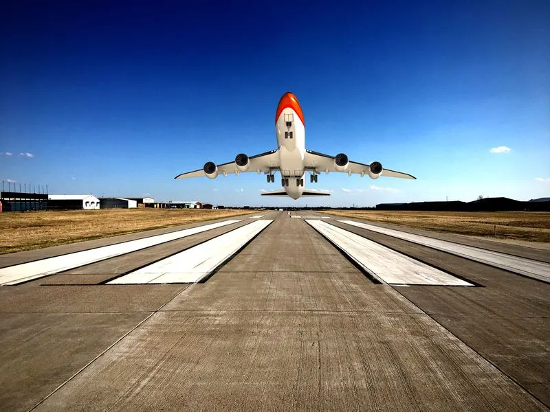
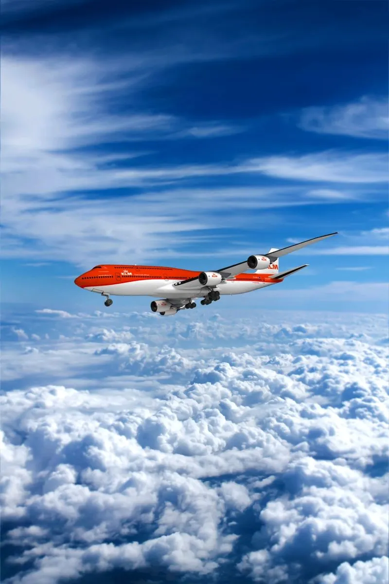
6) Rendered Images:
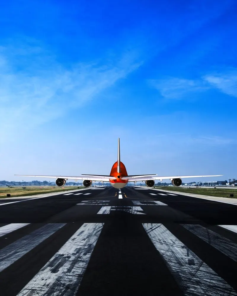
7) Conclusion:
All parts of Boeing 747 are successfully modeled and appropriate appearances are given to each part.
The assembly of the parts are done rightly with proper mates and constrains.
Preprocessing, Camera setup, Light setup, Background and environment setup is done properly.
Successfully rendered images of Aircraftusing photo view 360.