Modelling, assembly and rendering of American chopper bike
TITLE
Modelling, Assembly and Rendering of Chopper Bike in Solidworks
OBJECTIVE
To be able to recreate the parts of chopper bike, assembled them as shown in video and make them look as realistic as possible.
INTRODUCTION
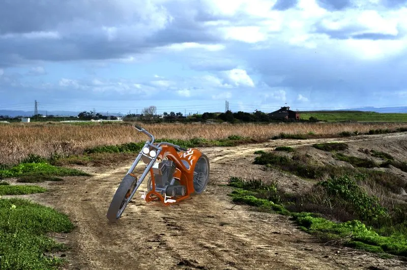
This report is about design and assembly of American chopper bike in solidworks and rendering the bike using photoview 360. Solidworks is a 3D CAD software using which i have modelled the different parts of the bike, assembled them in proper manner, adjusted bike orientation to make it look like what it would be in real world, then using photoview 360 which is rendering software, I have render the images of bike in different views.
DESIGN METHODOLOGY
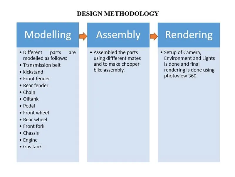
Bottom up approach:
In this project bottom up assembly approach is used, where all the parts are created first and then they are assembled using constrains and mates to form chopper bike assembly. Then rendering is done using photoview 360
Top down approach:
In the top-down approach, an overview of the system is prepared without going into detail of any part of it. In this approach you start your work in the assembly and built parts to fit in the assembly. Geometry of one part is used to help define the other parts.
.
DESCRIPTON
Sketch tools used in project
- Sketch: To create a new sketch or edit previous sketch.
- Line, Circle, Spline, Rectangle, Arcs, Ellipse, Slots, Sketch fillet.
- Trim Entities: Used to trim extra sketch entity.
- Extend Entities: Used to extend sketch entity to meet another entity.
- Convert Entities: Converts selected edges and sketch entities into identical entities on sketch plane.
- Offset Entities: Offsets the selected sketch entities by specified distance.
- Mirror Entities: Mirrors the selected sketch entities about centerline or plane reference.
- Linear pattern: This tool patterns the selected sketch in one or two linear direction.
- Circular Pattern: This tool patterns the sketch entities in circular instances.
- Dynamic Mirror: This tool creates sketch entities that are mirror about selected entity as you draw them.
- Blocks: This tool is used to make, save, edit, and insert blocks for drawing items and sketch entities that you use often.
Features used in this Project
- Extrude Boss/Base: This feature extrudes the selected sketch in one or two directions and creates a solid Feature.
- Revolve Boss/Base: This feature revolves the selected sketch around the selected axis to create a solid feature.
- Sweep Boss/Base: This feature sweep the close profile along the path that is open or close to create solid feature.
- Lofted Boss/Base: This feature is used to add material between two or more profile to create a solid feature.
- Extrude Cut: This feature cuts the solid model by extruding the sketch in one or two direction.
- Revolve Cut: This feature cuts the solid model by revolving the sketch around the selected axis.
- Sweep Cut: This feature cuts a solid model by sweeping close profile along the selected path that is open or close.
- Fillet: This feature creates rounded internal or external face along one or more edges on solid or surface feature.
- Chamfer: This feature creates a beveled feature on selected edges, faces on solid model.
- Linear Pattern: This feature patterns features, body or faces in ore two linear direction.
- Circular Pattern: This Feature patterns feature, face or body in number of instances around the selected axis.
- Mirror: This feature is use to mirror body, faces or feature about the selected plane or geometry.
- Curve driven pattern: This feature patterns features, faces, body based on the curve.
- Shell: This feature is use to create hollow bodies from solid bodies by specifying the thickness of wall.
- Reference Geometry: This feature is used to create reference point, plane, coordinate system and axis by selection of different plane, points, lines, distance etc.
- Project Curve: This feature is used to create curve in 3D using two curves in different planes.
- Composite Curve: this feature combines selected edges, points and sketches into a single curve.
- Dome: This feature creates dome on selected face.
- Split: This feature creates multiple bodies from single body. The sketch is not required to be closed profile.
- Combine: This feature is used to create single solid body from two or more bodies.
- Move/Copy Bodies: This feature moves, copy, rotates solid or surface bodies.
Surface tools used in project
- Surface Trim: Trims a surface when it intersects with another surface, plane or sketch.
- Boundary surface: Creates a surface between profiles that can be tangent or curvature that is continuous in all directions.
- Swept surface: Creates a surface by sweeping sketch along the guide curve.
- Surface loft: Creates a lofted surface between two profiles or sketches.
- Surface knit: Creates two or more adjacent surfaces into single surface.
- Extrude Surface: Extrude a sketch in one or two direction to create a surface feature.
Parts
- Transmission Belt: It is use to transfer power from engine to gearbox.
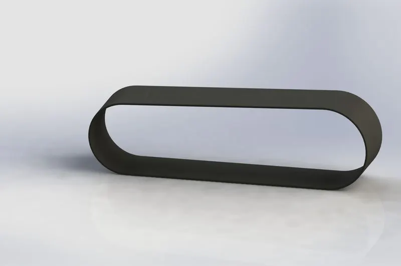
Sketch tools used: 3 point arc, lines
Features used: Extrude boss, Fillet
Appearance: Matte rubber
- Kick stand: It is used to support the bike also known as side stand.
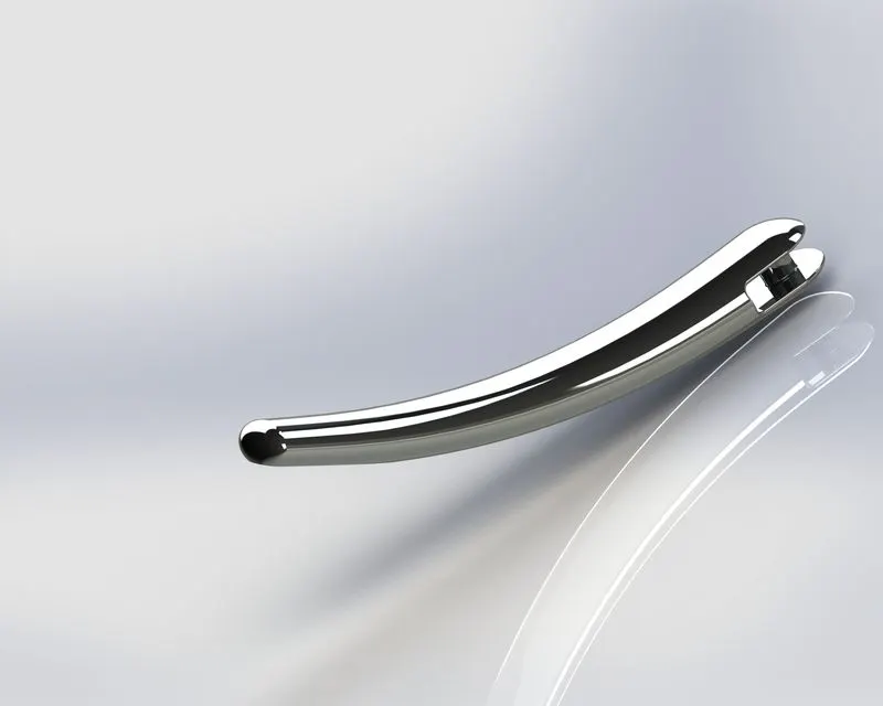
Features Used: Lofted base/boss, Dome, Extruded cut, Split, Extruded Boss/Base, Fillet
Appearance: Chromium plate
- Front fender: purpose of fender is to prevent mud, dust, dirt being thrown into air by rotating tyre.
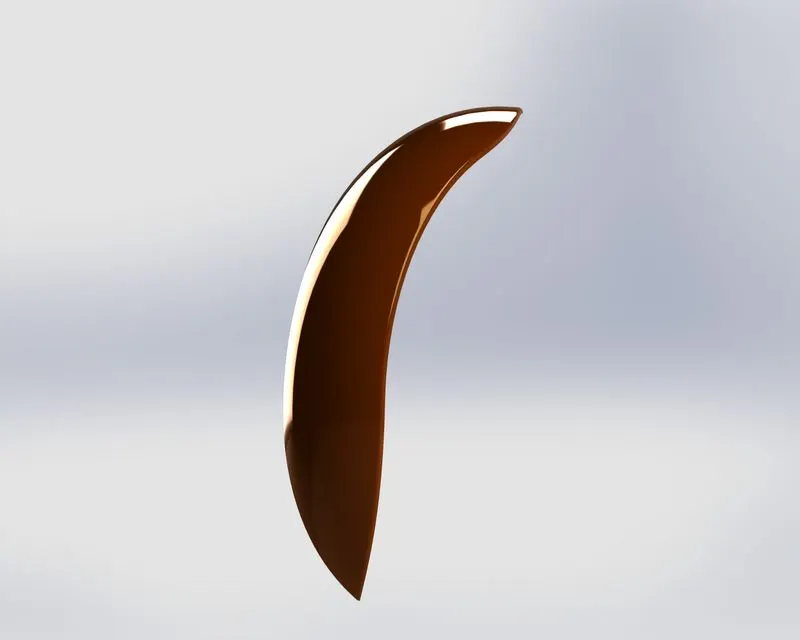
Sketch tools used: Dynamic Mirror, Trim entities, Offset entities.
Features used: Revolve, Split, Fillet
Appearance: painted car siena
- Rear Fender: Function of rear fender is same as front fender.
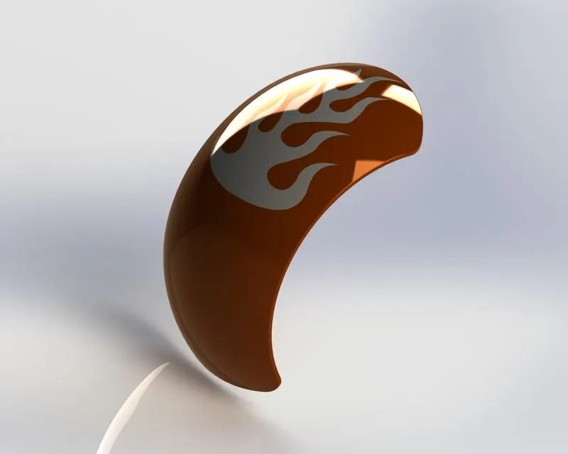
Sketch tools used: Offset entities, Trim entities
Features used: Revolve, Split, Fillet, Shell
Appearance: painted car siena
- Chain: Chain is used to transmit power from gearbox to wheel.
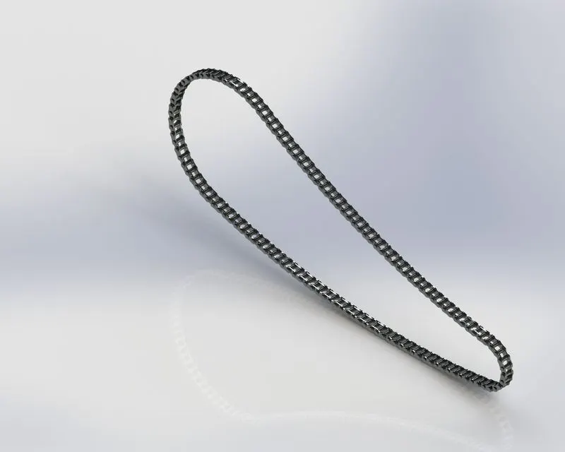
Sketch tools used: Sketch, Trim, Curve driven pattern, Blocks
Features used: Extrude Boss, Fillet, Mirror
Appearance: Chromium plate
- Oil Tank: It is used to store oil required by engine for its smooth operation and lubrication.
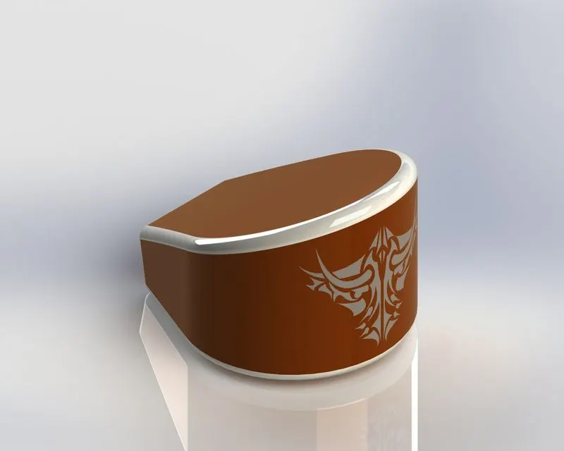
Sketch tools used: Mirror entities
Features used: Extrude boss, Fillet, Combine, Shell
Appearance: Painted car siena
- Pedal: Pedal is used to rest the foot of rider for comfortable position on bike.
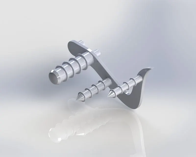
Features used: Extrude boss, Dome, Revolve, Fillet, Chamfer, Linear pattern
Appearance: Chromium plate
Wheel: Wheel is a circular part that rotates around the axle when a thrust or torque is provided.
Front wheel and Rear wheel is consist of 4 and 5 solid bodies respectively as follows:
- Rim
- Tyre
- Caliper
- Rotor
- Sprocket ( Present in rear wheel only)
- Front wheel:
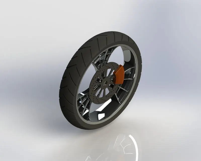
Sketch tools used: offset entities, Convert entities, trim entities, linear pattern
Features used: Revolve, Extrude boss, Extrude cut, Revolve cut, combine, Circular pattern, fillet, Chamfer, Revolve boss
Appearance:
|
Tyre |
Matte rubber |
|
Rim |
Chromium plate |
|
Caliper |
Painted car siena |
|
Rotor |
Carbon steel |
- Rear wheel:
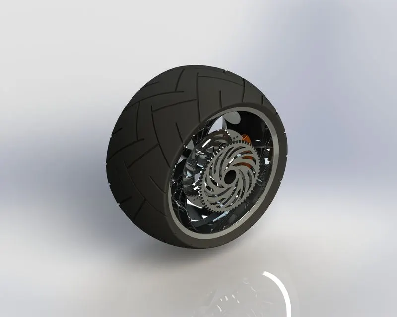
Sketch tools used: offset entities, Convert entities, trim entities, linear pattern
Features used: Revolve, Extrude boss, Extrude cut, Revolve cut, combine, Circular pattern, fillet, Chamfer, Revolve boss
Appearance:
|
Tyre |
Matte rubber |
|
Rim |
Chromium plate |
|
Caliper |
Painted car siena |
|
Sprocket |
Chromium plate |
|
Rotor |
Carbon steel |
- Front Fork: It is used to steer the bike also attach front wheel using axle mounted between two yokes,
also headlights are also mounted on front fork. Front suspension is also mounted on the front fork.
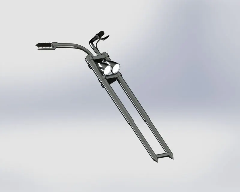
Sketch tools used: Trim, Convert entities
Features used: Revolve boss, extrude boss, linear pattern, Fillet, Extruded Cut, Dome, Revolved cut,
Move body, Sweep boss, Combine, Mirror, Project curve
Appearance:
|
Whole part |
Chromium plate |
|
Handle Grips |
Glossy rubber |
|
Headlight surface |
Area light |
- Chassis: Chassis is the metal tube frame on which bike components are mounted. Engine, Rear wheel , front fork, Gas tank are mounted on the chassis.
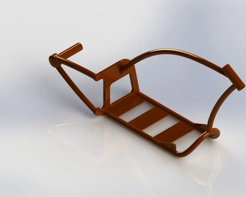
Sketch tools used: Offset entities, Convert entities, Trim entities
Features used: Project curve, Sweep, mirror, Extruded Boss, Extruded cut, Chamfer, Fillet, Dome, Split, Revolve, Combine,
Appearance: Painted>Car >seina
- Engine: Engine is the most important part of the bike. It gives the power required to drive the bike.
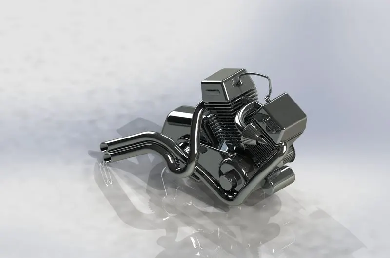
Sketch tools used: Trim, Convert entities, Offset entities,
Features used: Extruded boss, Revolve, Fillet, Circular pattern, Dome, Extrude cut, Chamfer, Linear pattern, Mirror, Sweep, Combine, Project curve, Composite curve
Appearance: Chromium Plate
- Gas Tank: Gas tank is used to store fuel for bike. Many surface tools are used while creating Gas tank.
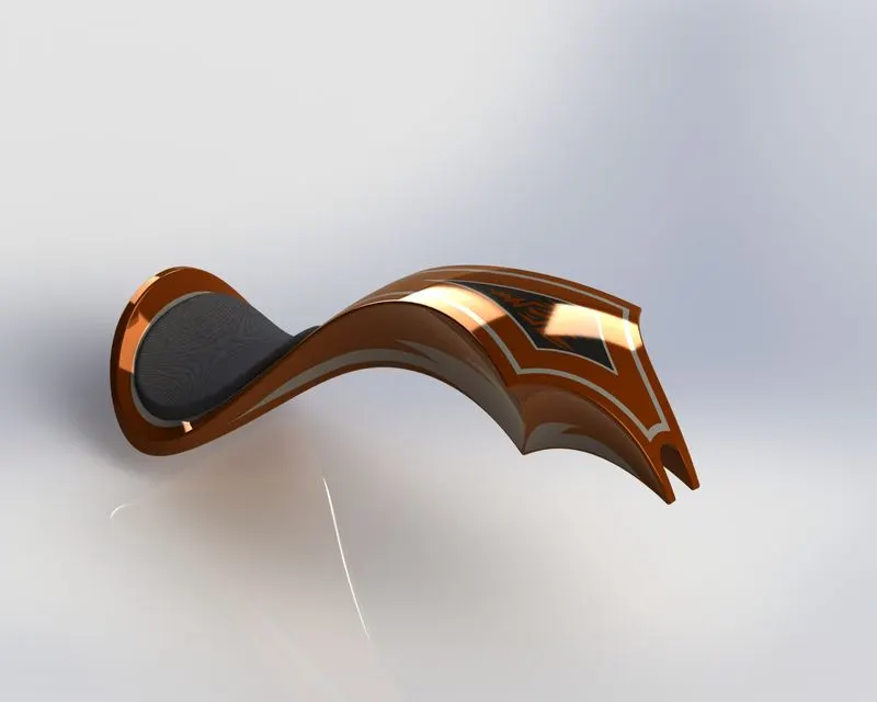
Features used: Project curve, Mirror, Split, Fillet, Sweep cut, Shell
Surface tools used: Surface sweep, Surface trim, Surface loft, Boundary Surface, Surface knit, surface extrude
Appearance:
- Tank : Painted > Car > siena
- Seat: Grey cotton
Assembly
For assembly of chopper bike we have fix chassis as reference for all other parts. In the following order we have assembled all the parts with given mates.
Features that are used for assembly of chopper bike: Insert parts, Mates
Mates:
Creates geometric relationships between assembly components to define the allowable direction of linear or rotational movement of components. We can move a component within its degrees of freedom to visualize the assembly's behavior.
|
Sr.no |
Part |
Mates |
|
1 |
Chassis |
Fix |
|
2 |
Engine |
Coincident, Distance |
|
3 |
Pedal |
Cocentric, coincident |
|
4 |
Kickstand |
Cocentric, Width, limit angle, Tangent |
|
5 |
Transmission belt |
Cocentric, width, Angle |
|
6 |
Oil Tank |
Coincident |
|
7 |
Rear Wheel |
Cocentric, Coincident, Parallel, Width |
|
8 |
Rear fender |
Cocentric, Coincident, Parallel |
|
9 |
Chain |
Cocentric, Width, Parallel |
|
10 |
Gas tank |
Coincident, Distance |
|
11 |
Front fork |
Cocentric, Width, Limit angle, Coincident |
|
12 |
Front wheel |
Cocentric, Coincident, Tangent |
|
13 |
Feont fender |
Coincident |
Rendering
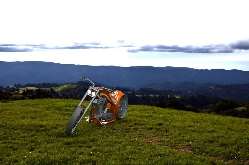
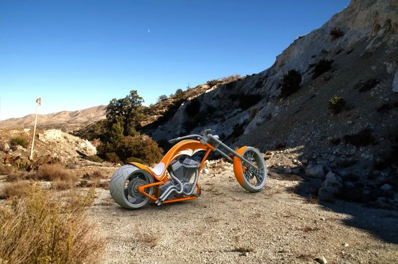
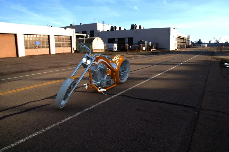
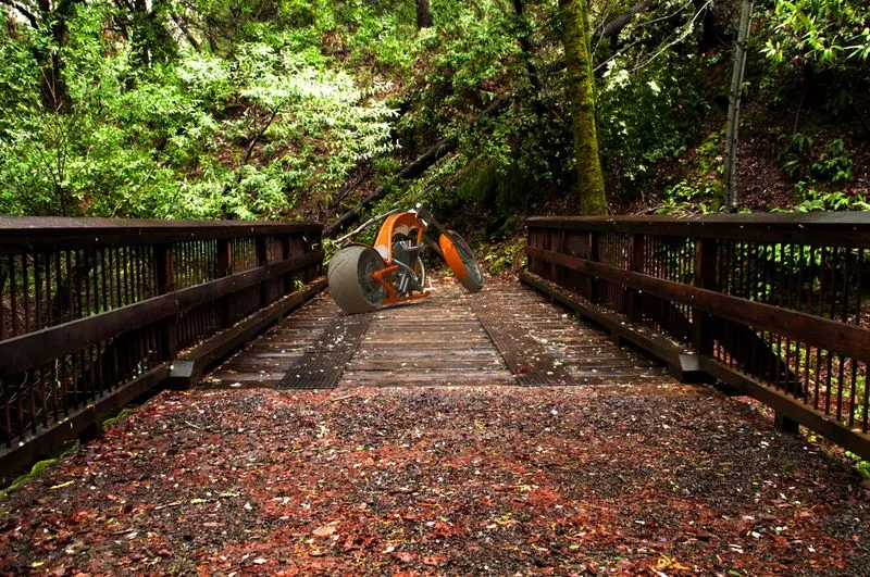
Before rendering of model we have done some preprocessing. This includes applying decals to fuel tank, oil tank and rear fender. After that to make bike look like real, we have inclined bike to make ground contact with kickstand. Also the handle is rotated by some degrees to make it look real bike is parked.
After preprocessing we have done camera setup, background and environment conditions, and lights position adjustments. Then using photoview 360 we have done final rendering.
Assembly pictures:
1) Back view
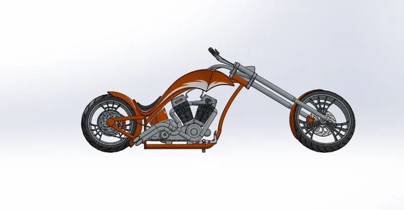
2) Top view
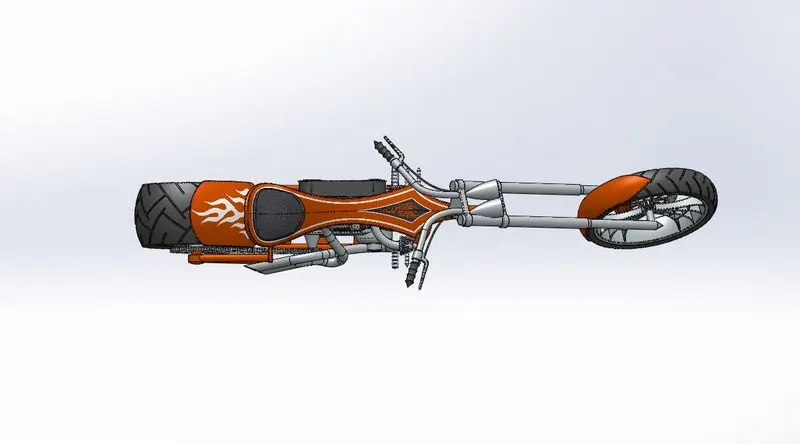
3) Isometric view
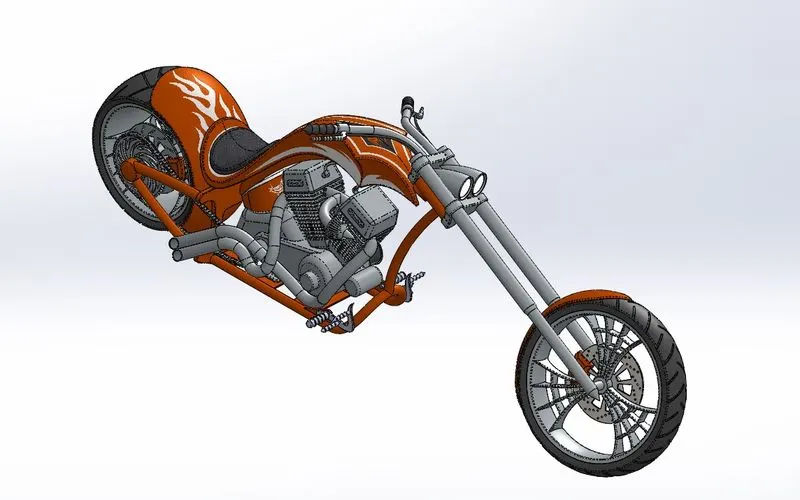
4) Side view
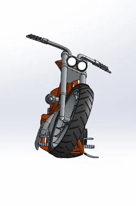
5) Camera view
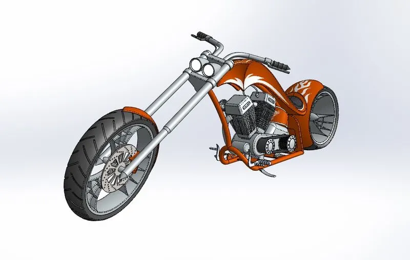
Rendered Images:
1)
2)
3)
4)
5)
CONCLUSION
- All parts of American chopper bike are successfully modeled and appropriate appearances are given to each parts.
- The assembly of the parts are done rightly with proper mates and constrains.
- Preprocessing, Camera setup, Light setup, Background and environment setup is done properly.
- Successfully rendered images of American chopper bike using photoview 360.
NOTE: Solidworks visualize is not working in my computer so I am not able to attach the photorealistic rendered images.