Aston Martin ONE-77 Challenge-11 (Project) Final Assembly
Title: Surface modelling of Aston Martin one-77
Objective: To learn the different surface modelling techniques to successfully model Aston martin one-77.
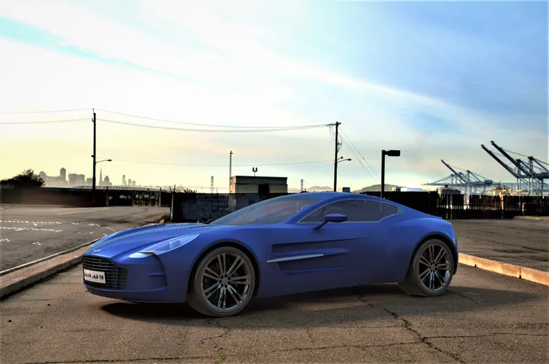
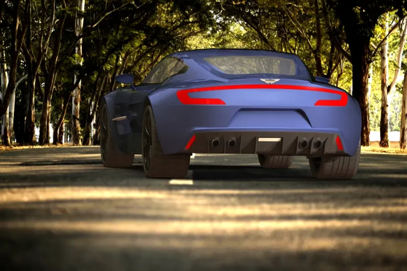
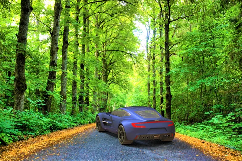
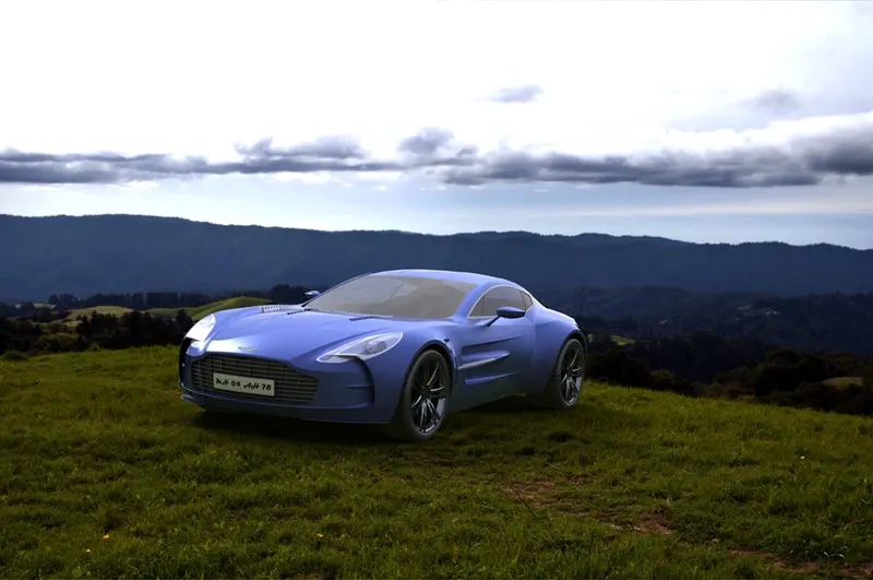
Introduction: This report is about surface modelling and solid modelling of Aston martin one-77. In this project I have applied various surface modelling tools to create outer surface of car body. At some places solid modelling is also used. After successful modelling of each parts, I have assembled them using various mates and constrains to create whole assembly. After that using photoview 360 I have rendered the images of one-77 which looks realistic. The rendering process involves setup of camera, lights, background and environment.
Design methodology: For assembly of one-77 I have used Bottom up approach in which all the parts are prepare according to dimensions and then assembled.
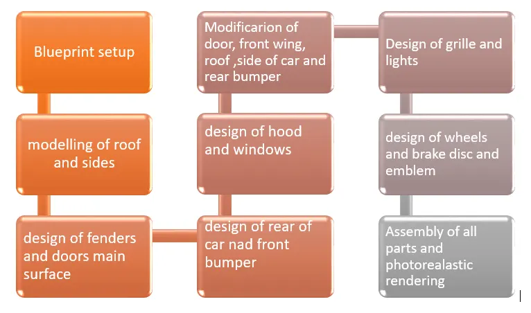
Other approach can be used is Top down approach: In the top-down approach, an overview of the system is prepared without going into detail of any part of it. In this approach you start your work in the assembly and built parts to fit in the assembly. Geometry of one part is used to help define the other parts.
Sketch tools used in this project:
- Sketch: To create a new sketch or edit previous sketch.
- 3D Sketch: To create a new sketch in 3 dimensions.
- Smart Dimensions: Creates dimensions for selected one or more 2d or 3d sketch entities.
- Line, Circle, Spline, Rectangle, Arcs, Ellipse, Slots, Sketch fillet.
- Trim Entities: Used to trim extra sketch entity.
- Extend Entities: Used to extend sketch entity to meet another entity.
- Convert Entities: Converts selected edges and sketch entities into identical entities on sketch plane.
- Offset Entities: Offsets the selected sketch entities by specified distance.
- Mirror Entities: Mirrors the selected sketch entities about centerline or plane reference.
- Linear pattern: This tool patterns the selected sketch in one or two linear direction.
- Circular Pattern: This tool patterns the sketch entities in circular instances.
Features used in this Project
- Extrude Boss/Base: This feature extrudes the selected sketch in one or two directions and creates a solid Feature.
- Revolve Boss/Base: This feature revolves the selected sketch around the selected axis to create a solid feature.
- Sweep Boss/Base: This feature sweep the close profile along the path that is open or close to create solid feature.
- Extrude Cut: This feature cuts the solid model by extruding the sketch in one or two direction.
- Revolve Cut: This feature cuts the solid model by revolving the sketch around the selected axis.
- Fillet: This feature creates rounded internal or external face along one or more edges on solid or surface feature.
- Chamfer: This feature creates a beveled feature on selected edges, faces on solid model.
- Linear Pattern: This feature patterns features, body or faces in ore two linear direction.
- Circular Pattern: This Feature patterns feature, face or body in number of instances around the selected axis.
- Mirror: This feature is use to mirror body, faces or feature about the selected plane or geometry.
- Reference Geometry: This feature is used to create reference point, plane, coordinate system and axis by selection of different plane, points, lines, distance etc.
- Project Curve: This feature is used to create curve in 3D using two curves in different planes.
- Combine: This feature is used to create single solid body from two or more bodies.
- Move/Copy Bodies: This feature moves, copy, rotates solid or surface bodies.
- Flex: Flexes solid or surface bodies.
Surface tools used in project
- Surface Trim: Trims a surface when it intersects with another surface, plane or sketch.
- Boundary surface: Creates a surface between profiles that can be tangent or curvature that is continuous in all directions.
- Swept surface: Creates a surface by sweeping sketch along the guide curve.
- Surface loft: Creates a lofted surface between two profiles or sketches.
- Surface knit: Creates two or more adjacent surfaces into single surface.
- Extrude Surface: Extrude a sketch in one or two direction to create a surface feature.
- Filled surface: patches a surface within boundary defined by edges, sketches or curve.
- Offset surface: Creates an offset surface using gaps.
- Ruled surface: Inserts ruled surfaces in a specified directions from edges.
- Delete faces: Delete faces from surface bodies or solid body.
- Extend Surface: Extend one or more edges or faces on surface, based on end conditions and extension type.
- Split line: Projects a sketch on planner or curved face, creates multiple separate sketches.
Parts:
1) Main Body:
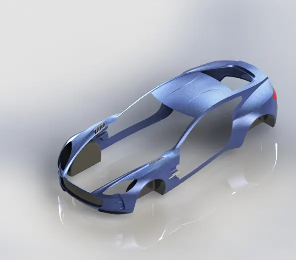
Main body of car is started with design of roof. First of all, projected curves are made using two sketches in top plane and side plane. After that using projected curves and sketches, surfaces are formed using Boundary/Filled surfaces. We can control the shape of surface using the end conditions like Curvature/Normal to profile etc. For all the parts half part is made first and then it is mirrored along the right plane.
Sketch tools used: Line, Spline, Circle, Arc, 3-D Sketch, Sketch picture, convert entities, offset entities, trim entities, extend entities, mirror entities
Features used: Extruded boss, cut extrude, fillet, chamfer, reference plane, project curve, linear pattern, combine and mirror.
Surface features used: surface loft, surface extrude, surface trim, surface fill, surface knit, Boundary Surface, Split Line, Extend surface, Ruled surface, surface offset, Delete face, Thicken.
2) Hood:
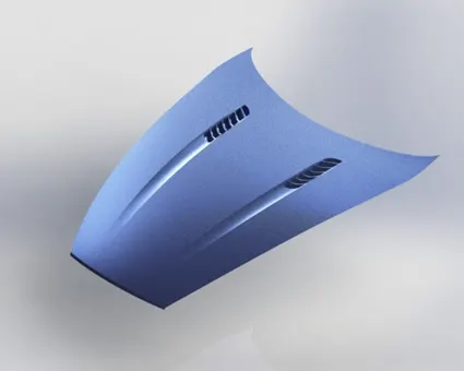
Sketch tools used: Line, Spline, Circle, Arc, Sketch, Sketch picture, convert entities, offset entities, trim entities, extend entities, mirror entities
Features used: Extruded boss, cut extrude, fillet, chamfer, reference plane, project curve, linear pattern, combine and mirror.
Surface features used: surface extrude, surface trim, surface knit, Boundary Surface, Split Line, Extend surface, Ruled surface, surface offset, Delete face.
Note: Using the same tools other parts of the car are modelled.
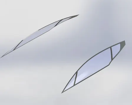
3) Window:
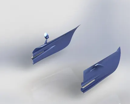
4) Door:
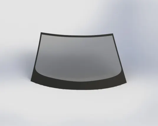
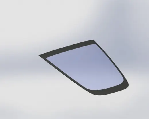
5) Front and Rear windshield:
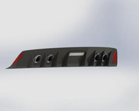
6) Rear bumper:
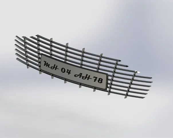
7) Grille:
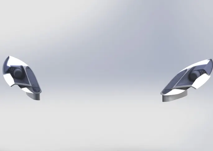
8) Lights:
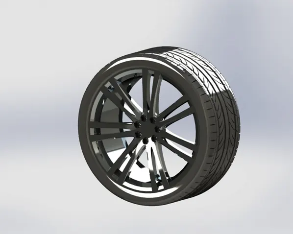
9) Tyre with Rims:
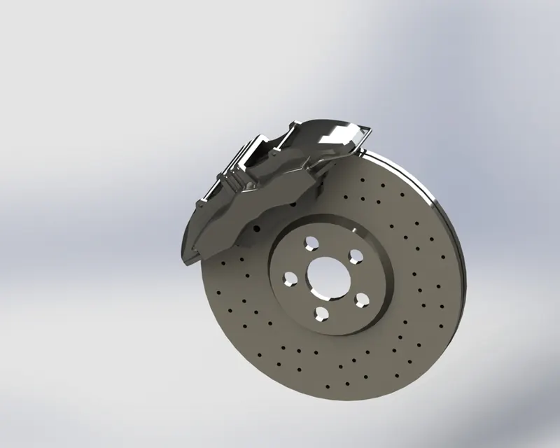
10) Brake disc with calliper:
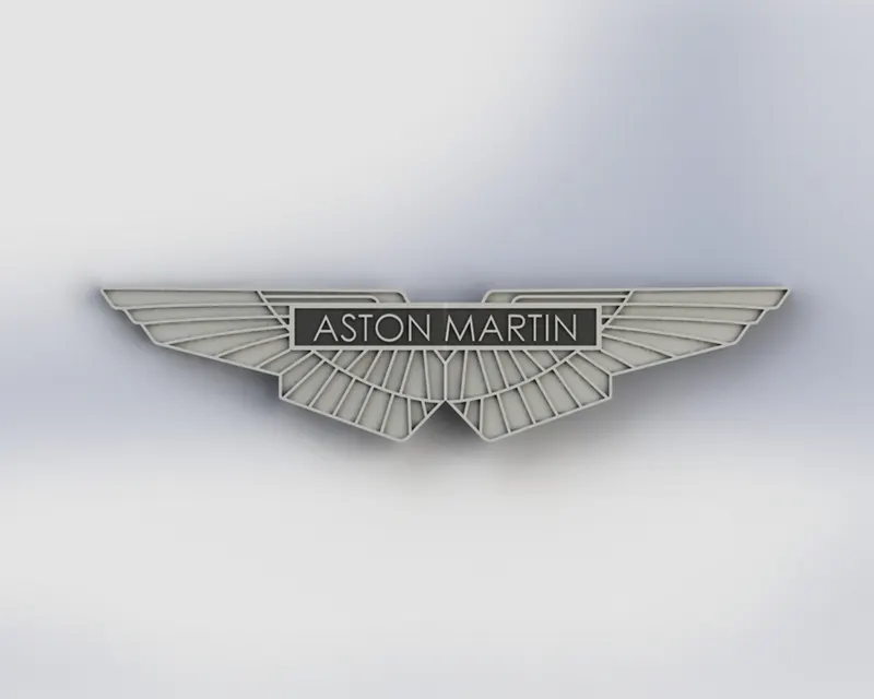
11)Emblem:
Assembly:
Mates:
Creates geometric relationships between assembly components to define the allowable direction of linear or rotational movement of components. We can move a component within its degrees of freedom to visualize the assembly's behavior.
|
Sr.no |
Part |
Mates |
|
1 |
Main Knitted body |
Coincident, Coincident, Coincident (Parts planes with assembly planes) |
|
2 |
Front and Rear windsheild |
Coincident, Coincident, Coincident(Parts planes with assembly planes) |
|
3 |
Window, Door |
Coincident, Coincident, Coincident(Parts planes with assembly planes) |
|
4 |
Hood, Rear bumper |
Coincident, Coincident, Coincident(Parts planes with assembly planes) |
|
5 |
Wheel subassembly |
Concentric, Distance |
|
6 |
caliper |
Angle |
|
7 |
Emblem, |
Coincident, Tangent, Coincident |
Assembly Images:
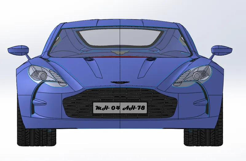
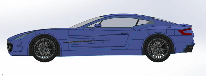
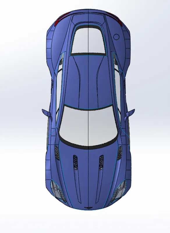
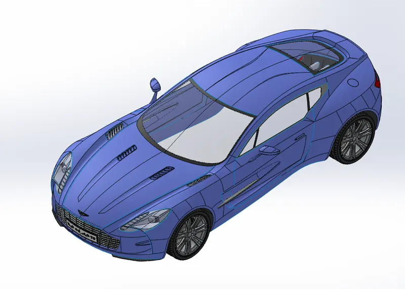
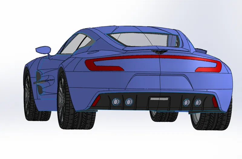
Rendered images:
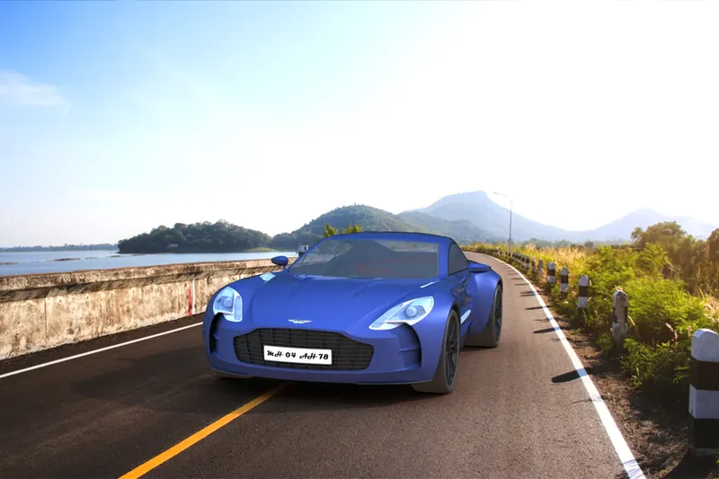
Conclusion:
In this project i have used various surface modelling tools to create surfaces of one-77. To create surfaces i have used alternatives methods to solve same problems. I have learned a lot about surface modelling and solid modelling. after successfully creating all the parts i have assembled them using various mates and constraints. Then using photoview 360 i have rendered the images which looks so realastic