Radar Mast & Final Assembly of Yacht
Project Report on Sunseeker Yatch Assembly
Aim : To Modelling of Sunseeker Predator Yatch.
Objective : To design the 3D model of ‘Sunseeker Predator Yacht’ by using solidworks.
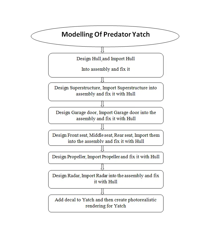
Introduction : Here we will discuss steps to design various parts of Sunseeker predator yatch using solidworks software. Also we will dicuss how to perform assembly of these parts and then we will perform photo realistic rendering of part files and assembly files by using Photoview 360 to give an asthetic look to our model.
Design Methodology :
Theory:
Sunseeker International is a British luxury yacht manufacturer recognized globally throughout the yachting industry. Founded in 1969 as Poole Power Boats by Robert and John Braithwaite, the company became Sunseeker International in 1985. The headquarters and main manufacturing facilities are located in Poole Harbour in Dorset, England. Chinese conglomerate Dalian Wanda Group acquired Sunseeker in 2013.
While ownership has changed hands in the last decade, Sunseeker yachts remain unmistakably British. The brand attracts a clientele that lives fast with an appreciation for high style. It’s no wonder Sunseeker yachts have made appearances in multiple James Bond films.
What started as a gamble for Robert Braithwaite in 1969 when he acquired the boat moulds from American boat builder Owens, Sunseeker has grown over the decades into one of the world’s leading luxury motor yacht builders. From the first 17 and 23 footers in the 1970s, Sunseeker now produces yachts ranging from 38 feet up to 161 feet in length. From the early beginnings, Sunseeker products have been marked by a passion for boating, intense attention to detail, impressive performance and luxurious materials.
Upon his death in 2019, thousands of Sunseeker workers and countless yacht enthusiasts world wide remarked upon the indelible impact that Robert Braithwaite had upon the yacht industry in the UK as well as around the world. Braithwaite’s legacy can be seen everywhere in the innovative and gorgeous Sunseeker yachts traversing the world’s waters as well as the yacht manufacturing and sales industry in the UK.
Today, Sunseeker employs over 2200 designers, engineers and craftsmen that produce 150 yachts a year that are sold globally to over 74 countries. While the company is no stranger to investment into innovative, new manufacturing techniques and technologies, Sunseeker maintains a relentless commitment to building hand-built and hand-finished vessels. The attention to detail by expertly skilled craftsmen leads to a product where a passion for boating is passed from builder to owner.
This commitment goes further for larger yachts being built at Sunseeker. For yachts over 100 feet, Sunseeker offers a true bespoke service where customers can be involved and specify individual preferences on nearly every element that goes into the yacht. From floor plans to furnishings, every detail matters as Sunseeker partners with buyers to create something truly individual and special.
Despite such attention going into each individual yacht produced, Sunseeker offers impressive variety across its models.
Sunseeker’s Predator line offers sizzle and excitement to buyers who desire a sporty, express style yacht. Predator yachts are thoughtfully crafted, uniquely styled and are just plain fast. Heads will turn as some Predator yachts achieve speeds in excess of 45 knots. The Predator line includes the Predator 50, the Predator 55 EVO, the Predator 60 EVO and the Predator 74.
Sunseeker pushes the boundaries with the Manhattan line which offers sleek European style paired with impressive interior volume and spaciousness. These yachts offer long range cruising without having to compromise on style and thrill. The line includes the Manhattan 52, 55, 66 and 68 models.
If you want sleek, sporty and spacious, the Sunseeker Sport Yacht line delivers in abundance. With a low profile, beautiful flowing lines, and elegant finishes throughout, these yachts offer the best of Sunseeker. The Sunseeker Sport Yacht is available in a 65 and 74 foot edition.
The Sunseeker Yacht line offers sizes ranging from 76 to 100 feet in length. These vessels represent the finest in Sunseeker style, design and functionality. Each element of these yachts has been meticulously considered to ensure an impressive combination of sophistication and detail typically limited to custom superyachts.
The largest vessels produced by Sunseeker are the Sunseeker Superyachts which include the 116 Yacht, the 131 Yacht, the 42M Ocean and the 50M Ocean. Sunseeker’s Superyacht series pushes the boundary of possibility in the manufacturing of yachts of this size. Whether it’s increasing interior volume, designing new and beautiful outdoor entertainment spaces or offering guests more direct access to the water, Sunseeker’s obsession with innovation is evident throughout these yachts.
Description :
In this project we will design following parts
- Blueprint Setup
- Propeller
- Radar
- Radarmast
- Hull
- Garage door
- Front seat
- Middle seat
- Rear seat
- Superstructure
- Radar
Let's discuss how to design these parts in detail as follows:
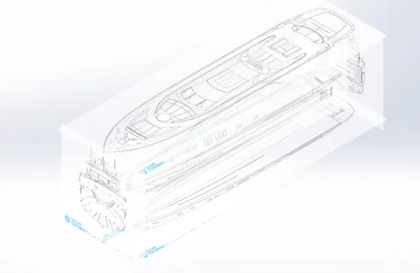
1. Blueprint Setup
This is the first step to start the model, using blueprints. In this part, all the blueprints of yacht are fixed to their respective planes. Such as blueprint of front view of yacht is fixed on Front plane, side view is fixed on mid plane, top view is fixed on top plane, back view is fixed on back plane & bottom view is fixed on bottom plane. Two planes are manually created using reference geometry feature & named as back plane and top plane. Here top plane renamed as bottom plane & right plane named as mid plane.
Isometric View
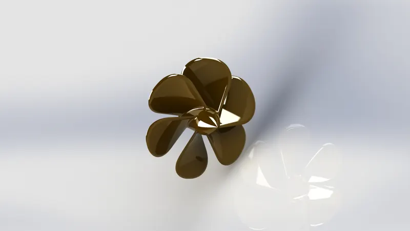
2. Propeller
Propeller is a rotary part of the yacht which is connected to the backside of hull. In propeller I have used following features i.e.;
Revolve - used to rotate the closed 2D sketch about a central axis.
Cut extrude - used to cut the extruded part. In this part, this feature is used to make a hole over the revolved part.
Loft – used to create vanes of propeller.
Circular pattern – used to copy the pattern in a circular path.
Fillet – used to give the rounded shape to all the corners.
Rendered Image :
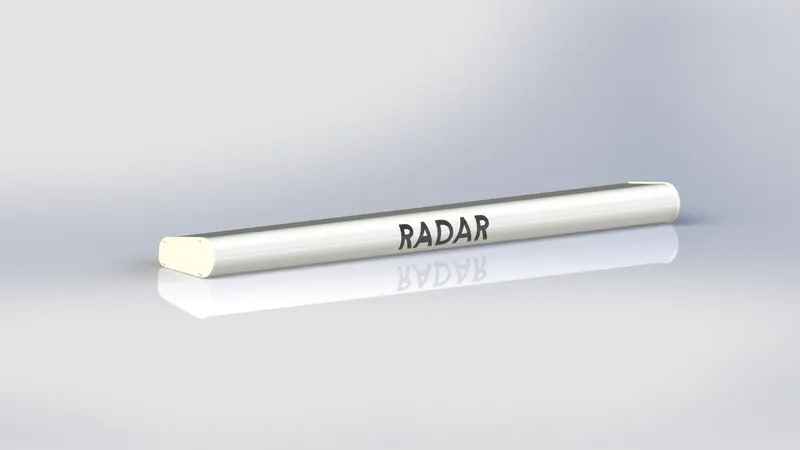
3. Radar :
Radar is a solid body, which is also a rotary part of the yacht. In this part following features are used:
Boss extrude - used to extrude the closed 2D sketch upto desirable height.
Cut extrude – used to cut the extruded part to make hole or cut the undesirable part.
Fillet – used to give the rounded shape to the corners & edges with a required radius.
Sketch pattern – used to pattern features aver a sketched point.
Mirror – used to mirror the body by giving the mirror face as reference.
Spit line – used to cut the face into parts. In radar, this feature is used to print the text over it.
Text – it is a 3D text to be printed over the radar, using split line command.
Renderded Image
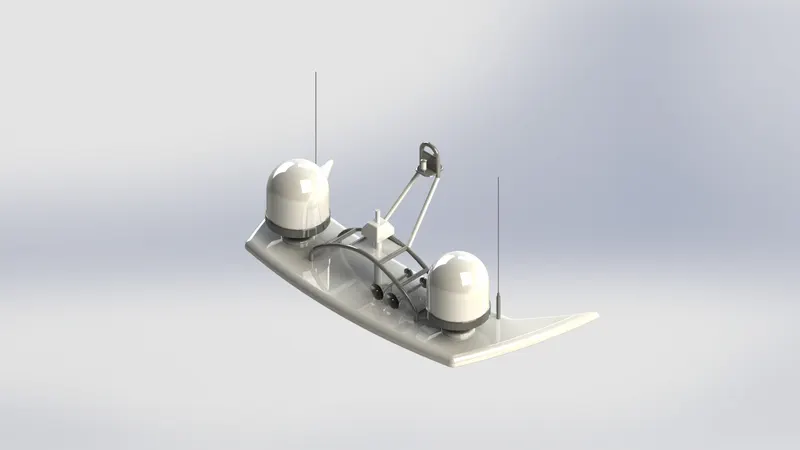
4. Radarmast :
Radar mast is a part which is placed over superstructure. Here, surface offset from back upper window of superstructure part is used as base reference to the radar mast. It consists of following features:
Boss extrude – used to extrude the closed sketch.
Revolve – used to revolve a closed sketch about an axis by giving one of the line as an axis.
Sweep - used to sweep a profile curve along a defined path.
Curve – used as a profile curve or guide curve to form surface & created using 2 2D sketch which is sketched into two different planes.
Fillet - used to give round shape to corners & edges.
Chamfer - used to give taper shape to corners & edges.
Shell – used to create a hollow body.
Combine – used to combine to solid bodies.
Mirror – used to mirror the half portion of superstructure to its opposite side using mid plane as a mirror face.
Renderded Image
5. Hull
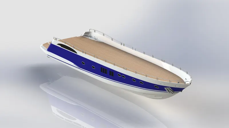
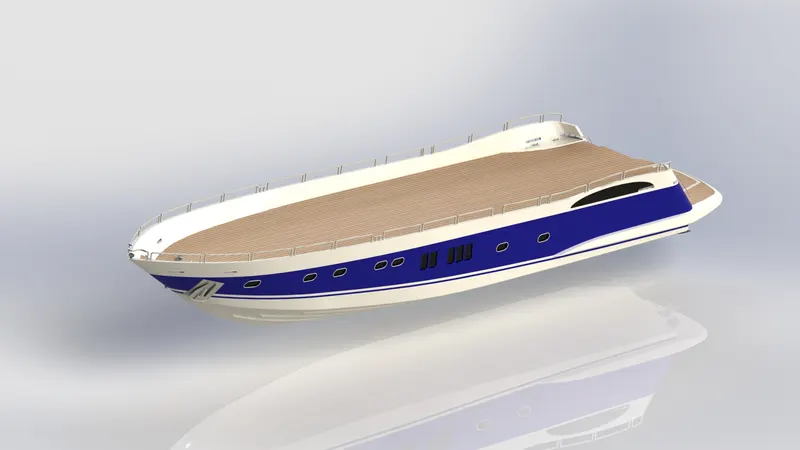
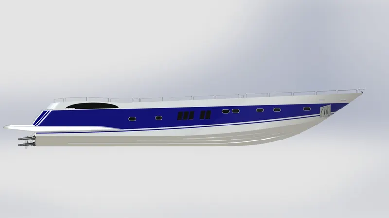
Hull is the base part of yacht. It consists of various surface features which helps in designing the complex shapes of this part. Using merge & knitted option the whole surface part then converted into solid. These are the following surface commands, used in this part:
Blueprint setup – used as a base to sketch the curves & outlines to create the surface.
Surface loft – used to create a surface using at least 2 profile curves & 2 guide curves.
Curve – used as a profile curve or guide curve to form surface & created using 2 2D sketch which is sketched into two different planes.
Surface trim – used to trim the surface.
Surface extrude – used to extrude the surface.
Surface knit – used to knit two or more than two surfaces.
Surface fill – used to create a surface using 4 boundary curves.
Shell – used to hollow the solid model with some thickness
Boss extrude – used to create a solid body from 2D sketch.
Cut extrude – used to cut the extruded part to form hole or cut the undesirable part.
Fillet – used to give round shape to the corners & edges .
Chamfer – used to give a taper to the corners & edges.
Linear pattern – used to pattern the feature over a linear path
Dome – used to create a dome over a solid part.
Split – used to cut out the solid part from the body.
Surface offset – used to offset the surface.
Delete face – used to delete the face.
sweep – used to form helical shape & pipe using a profile sketch & guide curve to give a path to the profile sketch.
Revolve – used to revolve a closed sketch about an axis by giving one of the line as an axis.
Mirror - used to mirror the half portion of hull to form a complete solid body.
Renderded Images
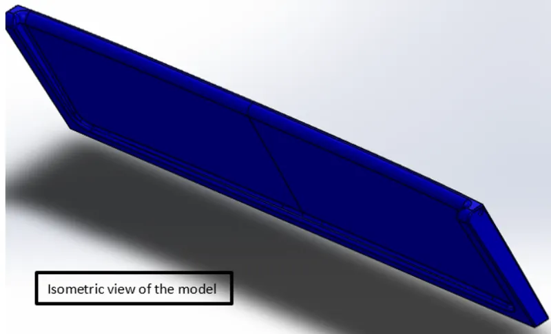
6. Garage door
It is an extracted part of hull, which is used as base of garage door. Garage door is a consists of following solid features:
Cut extrude - used to cut the extracted part of the hull.
Shell - used to hollow the solid body with some thickness.
Fillet - used to give the round shape to corners & edges.
Mirror - used to mirror the half portion of hull.
Renderded Image
7. Front seat
Surface loft - used to create a surface using at least 2 profile curves & 2 guide curves.
Surface knit - used to knit two or more than two surfaces.
Cut extrude - used to cut the extruded part to form hole or cut the undesirable part.
Fillet - & edges Used to give round shape to the corners.
Chamfer - Used to give taper shape to the corners & edges.
Mirror – used to mirror the half portion of front seat to opposite side.
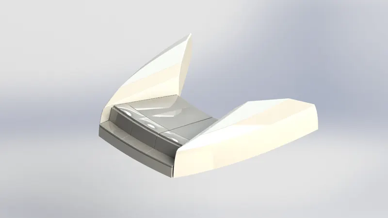
In front seat part, offset surface of hull is used as a base reference. It consists of following features:
Surface sweep – used to sweep the surface.
Surface trim – used to trim the surface.
Surface fill – used to fill the surface using 4 boundary curves.
Renderded Image
8. Middle seat
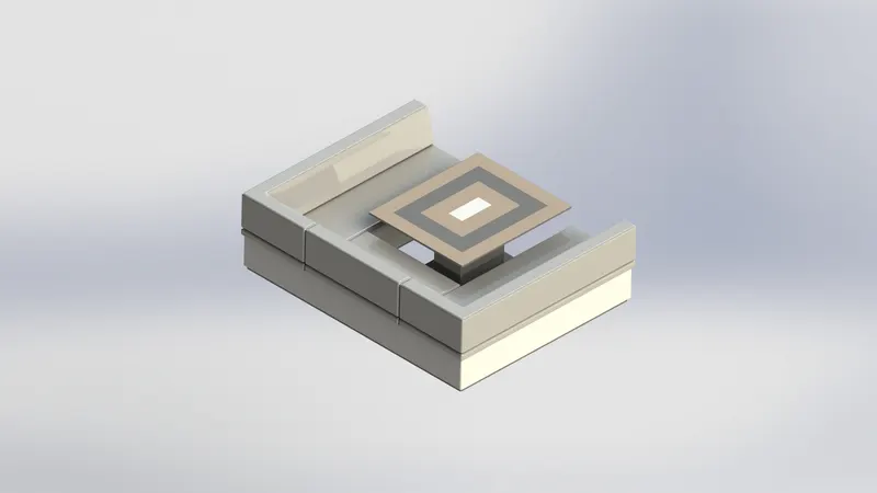
In middle seat part, offset surface of hull is used as a base reference. It consists of following features:
Boss extrude - used to create a solid body from 2D sketch.
Chamfer - Used to give taper shape to the corners & edges.
Fillet - Used to give round shape to the corners & edges.
Cut extrude – used to cut the extruded part.
Mirror – used to mirror the half portion of middle seat to opposite side.
Renderded Image
9. Rear seat
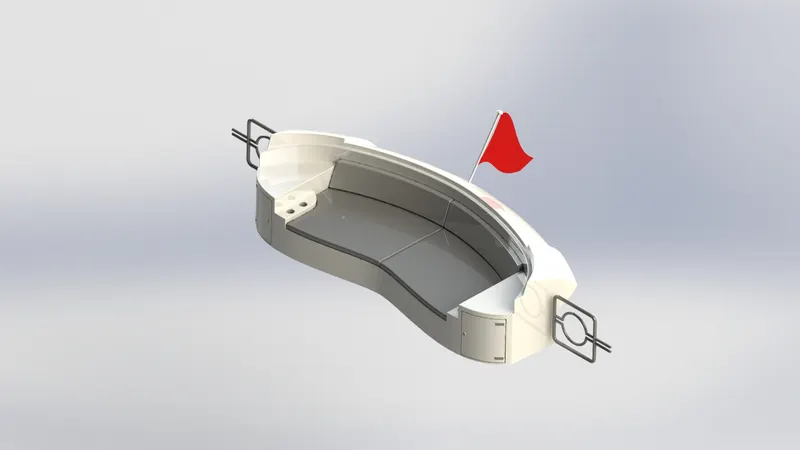
In rear seat part, offset surface of hull is used as a base reference. It consists of following features:
Surface sweep – used to sweep the surface.
Surface offset – used to offset the surface.
Surface trim– used to trim the surface.
Ruled surface – used to extend the surface in an angle using curve or line.
Surface knit - used to knit two or more than two surfaces.
Surface extrude - used to extrude the surface.
Surface extend – used to extend the surface.
Surface loft - used to create a surface using at least 2 profile curves & 2 guide curves.
Boss extrude - used to create a solid body from 2D sketch.
Sweep - used to form helical shape & pipe using a profile sketch & guide curve to give a path to the profile sketch.
Revolve – used to revolve a closed sketch about an axis by giving one of the line as an axis.
Fillet - Used to give round shape to the corners & edges.
Chamfer - Used to give round shape to the corners & edges.
Mirror - used to mirror the half portion of rear seat to opposite side.
Renderded Image
10. Superstructure
In superstructure, offset surface of hull is used as a base reference & blueprint setup is used for outline the sketches on respected plane. It is placed over the hull part.it consists of following features:
Surface extrude - used to extrude the surface.
Surface sweep – used to sweep the surface.
Curve - used as a profile curve or guide curve to form surface & created using 2 2D sketch which is sketched into two different planes.
3D sketch – used to sketch in 3D. in this part it is used to join the end points of curves.
Surface trim – used to trim the surface using surface or sketch entities as a trim tool.
Surface knit – used to knit the individual surface to combine it.
Ruled surface - used to extend the surface in an angle using curve or line.
Surface loft – used to create a surface using 2 guide curves & 2 profile curves.
Surface extend – used to extend the surface.
Surface extrude – used to extend the surface.
Surface offset – used to offset surface from the base .
Split line – used to split the face using sketch entity.
Delete face – used to delete the face.
Boss extrude – used to extrude the closed sketch.
Cut extrude – used to cut the extruded part to create hole or cut the undesirable part.
Fillet – used to give round shape to corners & edges.
Chamfer – used to give taper shape to corners & edges.
Mirror – used to mirror the half portion of superstructure to its opposite side using mid plane as a mirror face.
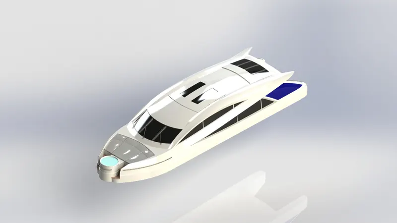
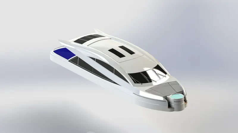
Renderded Images
11.Radar :
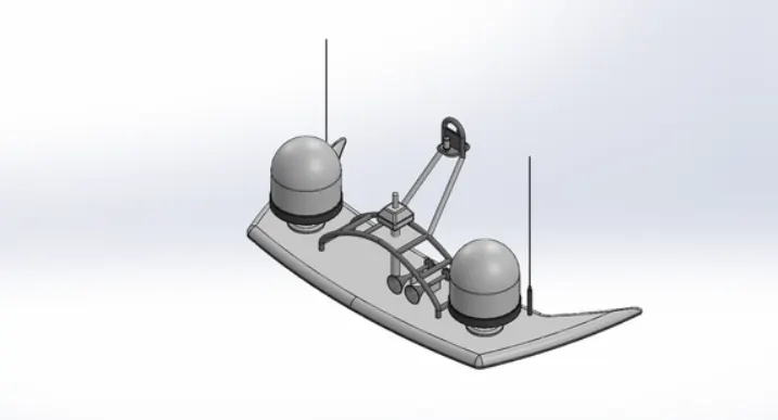
Radar is a detection system that uses radio waves to determine the distance, angle, and radial velocity of objects relative to the site. It can be used to detect aircraft, ships, spacecraft, guided missiles, motor vehicles, weather formations, and terrain.
Isometric View:
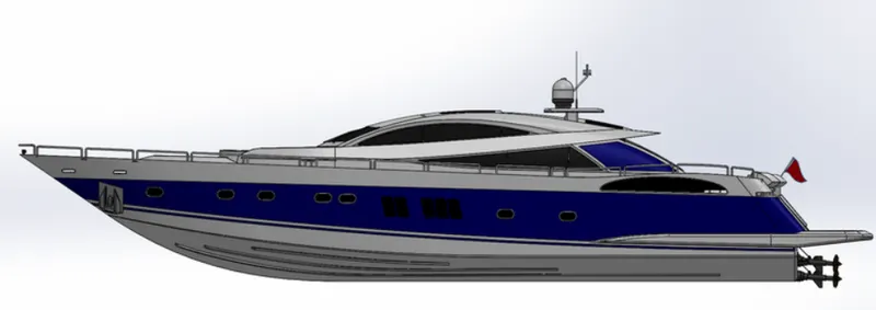
Yatch Assembly Isometric View
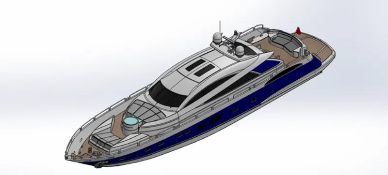
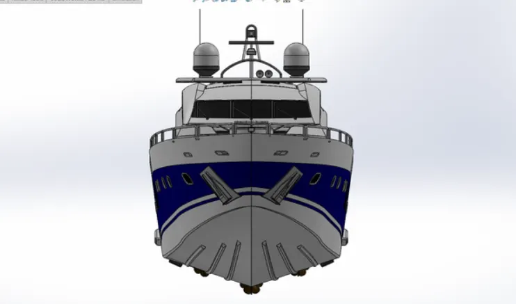
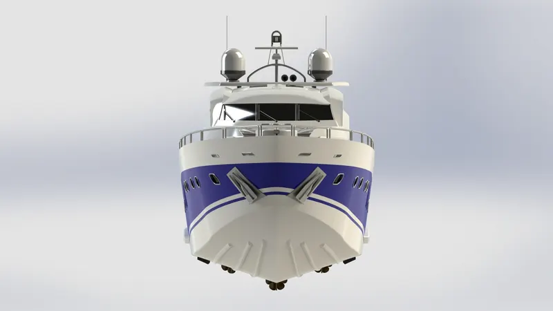
Yatch Assembly Front View
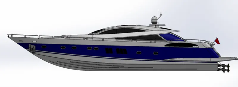
Yatch Assembly Right side view
Assembly Of Yatch :
Assembly of all the Parts which I have explained earlier, are fixed to each other using various mates. These mates provide all the parts a constrained motion according to their behaviour. The mates which are used in this assembly to combine all the parts are as follows:
Coincident mate – used to give a constrained reciprocating motion to the part
Concentric mate – used to aline the parts in one direction.
Angle mate - used to give a rotary motion to the parts about an axis or plane.
Hinge mate – used to provide the hinge on garage door part.
Tangent mate – used to give a constrained motion to the radar.
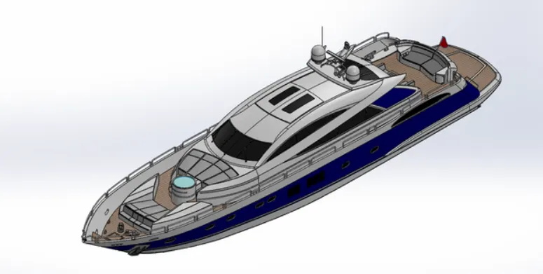
Isometric View
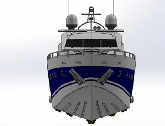
Front View
Right side view
Photorealistic rendering :
The rendering is done using photoview 360, which gives the aesthetic look to the yacht. The following steps are taken to render the yacht assembly:
- At first switch on the photoview 360 option,
Tools -> add-in-> photoview 360
- Then go to render tool option. In this section, all option is available to set the rendering.
- Set yacht assembly in a perspective view.
- Add camera to setup the view at an angle.
- Add lights, to get appropriate brightness over the assembly.
- Add background scene & environment scene to give the assembly an outstanding background.
- Click on option from render tool, tool bar to set the size of the window.
- Then, Preview window option is used to create a preview image of the setup.
- & after that final render is done using final render option given in render tool, tool bar.
- After getting desirable look to the assembly, click on save image option to save the image.
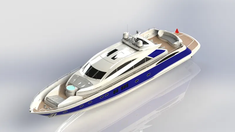
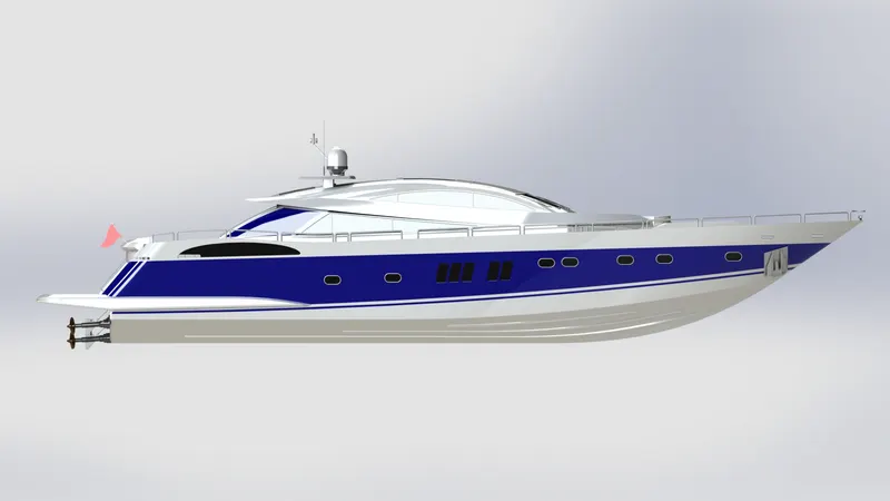
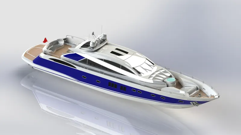
Here are some rendered images, which I have created using ‘Photoview 360’:
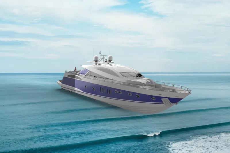
Similarly I have used Solidworks visualize and edited background of the Yatch by using backplate option and then performed the rendering.
Renderded Images
Solidworks Visualize :
Similarly I have used Solidworks visualize and edited background of the Yatch by using backplate option and then performed the rendering.
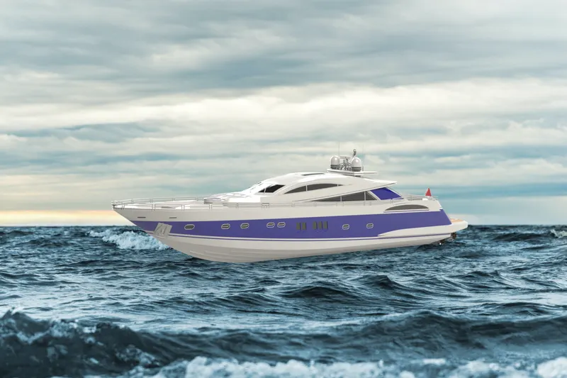
Conclusion : Modelling, Assembly and Photorealistic rendering of the Sunseeker Predator yatch is done successfully by using solidworks.
Google Drive Link: https://drive.google.com/drive/folders/1kXzUXmlz_tP8Diijmm4rYtIL6hObWE3p?usp=sharing