Radar Mast & Final Assembly of Yacht
Aim of the challange to create a m,odel of Radar Mast and Assembly of Yatch.
1.Radar Mast:
Modelling the Radar Mast :
- The Mast of a sailing vesselis a tall spar,or arrangement of spars, erected more or less vertically on the centre line of a ship or b
Its purposes include carrying sails, spars,and derricks,and giving necessary height to a navigation light,look out position,signal yard,control position,radio aerial or signal lamp.
Large ships have severalmasts,with the size and configuration depending on the style of ship.
- Here,the mast consists of 2 light bulbs alongisde 2 an
- This mast is easily modelled using the solid features such as Extruded Boss/Base, Revolved Boss/Base, Swept Boss/Base, etc.
- The horns are modelled by using the Shell featur This feature essentially removes off the inside material out of a solid 30 part, thereby making it hollow.
- The Mirror feature is used to mirror symmetr ic entities.
Feature used in Radar Mast:
- sketch
- extruded boss
- mirror
- chamfer
- fillet
- projection curve
- reference plane
- shell
- appereance.
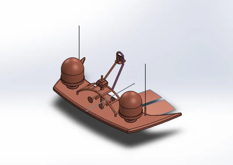
Isometric view of Radar mast:
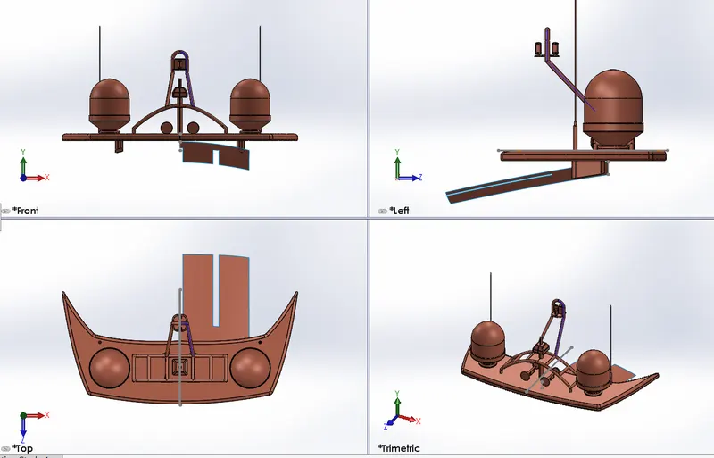
Other views of Radar mast:
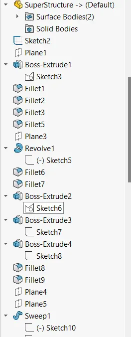
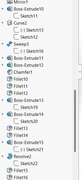
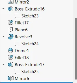
Feature tree plan:
2.Assembly of Yatch:
INTRODUCTION :
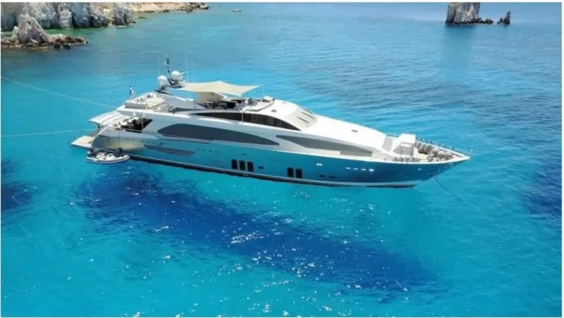
A yacht is a sail or power vesselused for pleasure,cruising,or rac ing. There is no standard def inition,so the term applies to such vessels that have a cabinwith amenities that accommodate overnight use.To be termed a yacht, as opposed to a boat, such a pleasure vessel is likely to be at least 33 feet (10 m) in lengthand may have been judged to have good aesthetic qualities. Originally,all yachts were made of wood,using a wooden keeland ribs,clad with planks.These materials were supplanted with iron or steel in steam yachts. In the 1960s fiberglass became a prevalent material.These materials and others continue in use. Whereas yachts of 79 feet (24 m) and below may be constructed of fiberglass,larger yachts are more likely to be constructed of steel,aluminum or composite fiber-reinf orced plastic.
Design methodology / approach
- Setting of Blueprint
- Propeller Modeling
- Radar Modeling
- Hull Modeling
- Garage door Modeling
- Rear,Front and Middle seat Modeling
- Superstructure Modeling
- Radar Mast Modeling
- Assembly of Yatch
- final Rendering
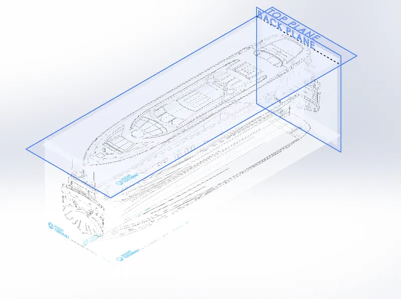
BLUEPRINT SETUP :
A blueprint is a reproduction of a technical drawing using a contact print process on light-sensitive sheets.
Introduced by Sir John Herchel in 1842,the process allowed rapid and accurate production of unlimited copies. It was widely used for over a century for the reproduction of specification drawings used inconstruction and industry.
A design blueprint is a high-levelplan that guides collaborators throughthe process of designing and contributing to the development of an open course. Its purpose is to visualize the overall architecture" of the course to guide the design,development,and cooperat ion process.
To design and model the yacht we need some kind of reference.that reference may be in form of some concept sketches or the desired views of the product from allthe sides (viz. Front view, side view,top view,bottom view,back view). we did the same,we set up blueprints of desired views of a yacht in the Solidworks environment and align each view in proportion to each other.Then we used this blueprint set up as a reference to design all the parts or bodies of the yacht accordingly.We insert the blueprint views in as a sketch and set up it inthe proper position.
ISOMETRIC VIEW:
PROPELLER:
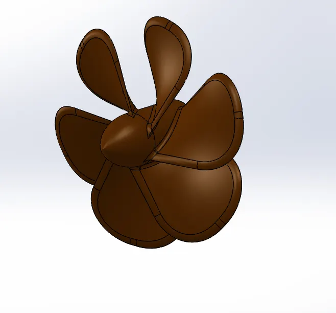
A propeller is a device with a rotating hub and radiating blades that are set at a pitch to form a helical spiral,that, when rotated,performs an action that is similar to Arch imedes' screw.It transforms rotational power into linear thrust by acting upona working f luid,such as water or air.
Design Methodology/ Approach:- As we know the design of the propeller is a rotating hub and contains blades on the hub.To create hub we simply used revolve feature. Then to create blades we used loft feature which includes two sketches on different planes. Finally,by using a circular pattern feature we created equally spaced six blades on the surface of the hub. Then we are using the fillets to get defined blade shape from the extrude lof rectangle.
ISOMETRIC VIEW:
RADAR:
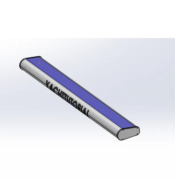
Radar is a detection system that uses radio waves to determine the range,angle,or veloc ity of objects. It can be used to detect aircraft,ships,spacecraft,guided missiles, motor vehicles, weather information,and terrain. A radar system consists of a transmitter producing electromagnetic waves in the radio or microwaves domain,a transmitting antenna,a receiving antenna (often the same antenna is used for transmitting and receiving),and a receiver and processor to determine the properties of the objects). Radio waves (pulsed or continuous) from the transmitter reflect off the object and return to the receiver,giving information about the object's location and speed.
Design Methodology/ Approach:- Design of radar is comparatively simple as it only includes creating some constraint sketches and then extruding them by using boss extrude features. Then we are using offset entites for 3mm on outside then extrude for 10mm . Then we are sketching on that face drawing a circle for 8 mm and extruded for 3mm then fillet as applied for the extruded circle. Then create a hexagon for 3.50 mm width then extrude cut for 1.5 mm depth..After that by using the sketch driven pattern on that face . Then by selecting the mirror feature mirror the object by selecting the right plane. Then apply fillet for the edges to avoid the shard edges bY selecting the bottom face we are creating a circle for 60mm for the particular dimension after that exit the sketch and extrude cut for 40mm apply thje fillets for the circle for 3mm. Then we are adding the text as YACHTUTORIAL on the either side of the radar. Apply the color and matrials for the radar and the text.
ISOMETRIC VIEW:
HULL:
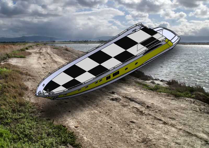
Hull is the base of the yacht and it is a symmetric model. Therefore it is enough to model one half and the other half could be mirrored.
First,the hull is developed in surface modelling, then after completing the model by surfaceit is converted to solid and proceeded with solid modelling. This is because hull consists of surface with complex curvature,therefore it is wise to modelwith surface then convert it as solid.
GARAGE DOOR:
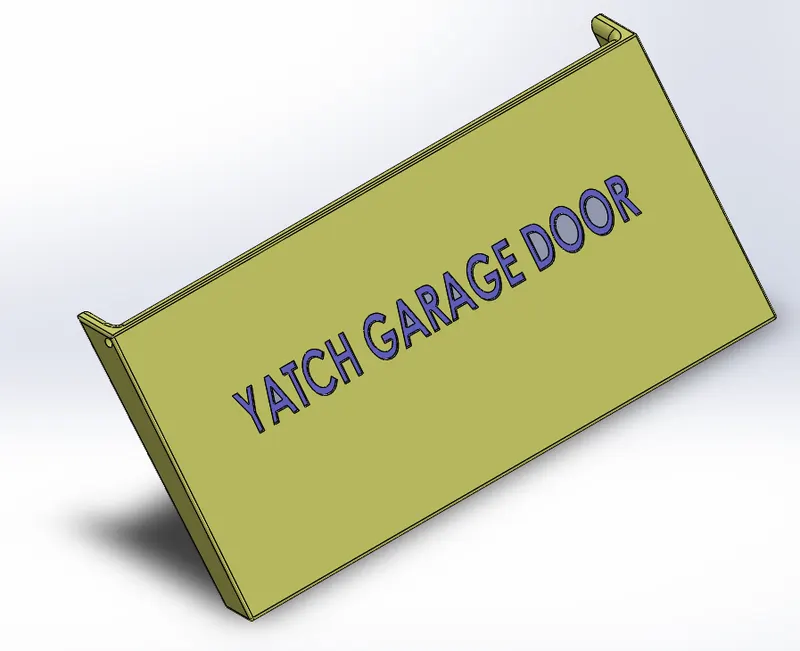
The part is modelled in a solid model which as saved with split command was used during moddeling hull.. The p[art is retrieved and is used for the construction of the garge door. It's a symmetric model therfore the other half is mirrored. The name is engraved as a YATCH GARGE DOOR by using the text feature and extruded cut feature is used to cut on the surface face on the door.
Commands used:
- Extrude cut
- Extruded boss
- shell
- fillet
- chamfer
- mirror
- text
- apperance.
isometric view:
FRONT SEAT
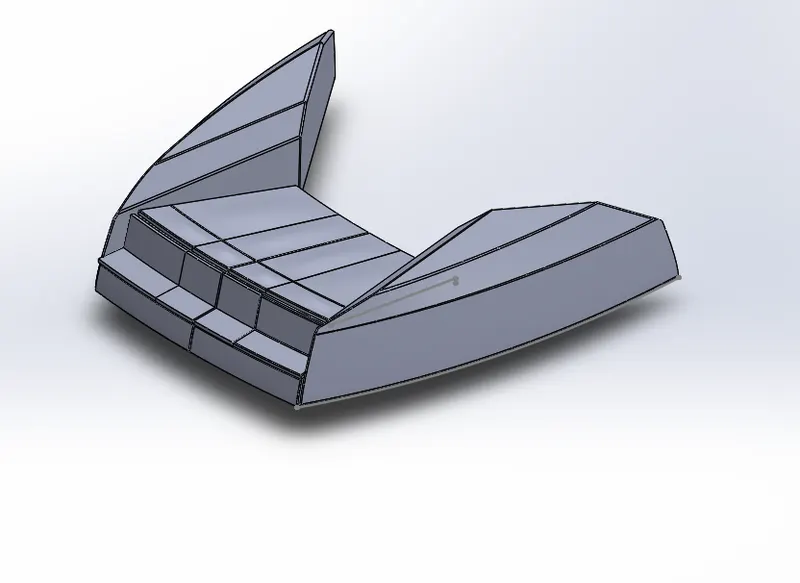
- Front seat is kept in the front portion of the hull and it has a seating with nice cushions are usually used in yacht.
Feature Used:
- Sketch
- plane
- Extruded boss
- Extruded cut
- fillet
- chamfer
- Mirror
- surface trim
- Reference plane.
Procedure to create a front seater:
- Insert the blueprint of the yacht ina new
- Create a projected portion in the side of the front seat of the yacht on the f loor of the hull using surface modelli
- Create the seating portion of the front
- Provide Iiilet and chamfer to all the required edges.
- Create additional cushion on the surface of the
- Provide Iiilet and chamfer to all the required edges.
- Create the remaining part of the front seat by mirroring the seat modelled till the last step.
- Apply appropriate colours to all the required surfaces.
Isometric View:
Raer Seat:
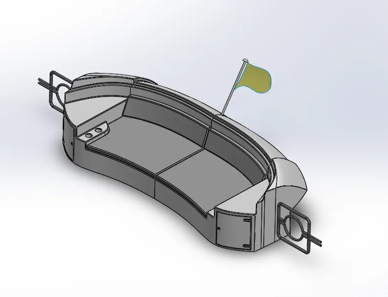
- The rear seat is kept at the rear end of the hull.
- The rear seat has a wooden cupboard and teacup holder as an additional featu
Procedure used in Rear seat modelling.
- Insert the blueprint of the yacht ina new par
- Create a rear portion of the rear seat of the yacht on the f loor of the hull using surface modelling.
- Create the basement of the rear sea
- Provide Iiilet and chamfer to all the required edges.
- Create a hand rest portion on the side of the rear
- Create a cup holder beside the hand res
- Create additional cushion on the surface of the
- Provide Iiilet and chamfer to all the required edges.
- Create a cub board below the hand rest portion.
- Create a gate on one side of the rear sea
- Create the remaining part of the rear seat by mirroring the seat modelled tillthe last step.
- Create a flag holder and flag above the rear portion of the rear
- Apply appropriate colours to all the required
Feature used:
- Sketch
- plane
- Extruded boss
- Extruded cut
- fillet
- surface trim
- Surface loft
- Reference plane.
- Apperance
Isometric View:
Mddel Seat:-
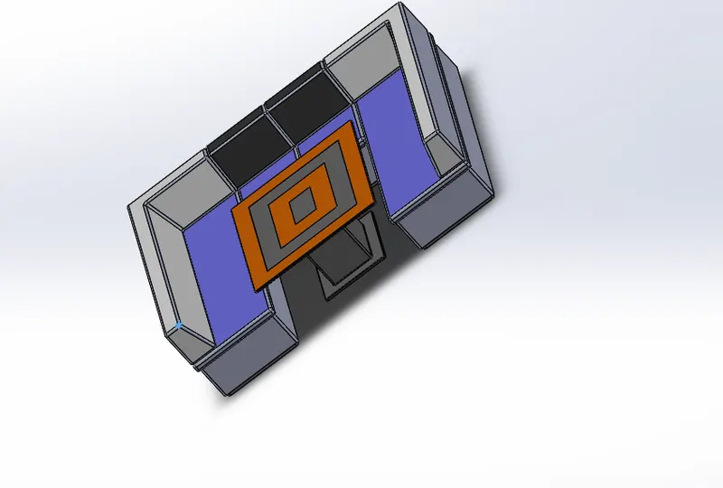
- The middle seat is kept just behind superstructu
- The middle seat consists of a table and chair
Procedure used in Middle seat modelling.
- Insert the blueprint of the yacht ina new par
- create the base of the middle
- Create the seating portion above the base of the
- Create the cushioning part of the seat above the seating portion.
- Provide Iiilet and chamfer to all the required
- Create the remaining part of the middle seat by mirroring the seat modelled tillthe last step.
- Create table at the centre of the middle sea
- Apply colour to all the required surf
features used:
- Sketch
- plane
- Extruded boss
- Extruded cut
- fillet
- surface trim
- Surface loft
- Reference plane.
- Apperance
Isometric Views:
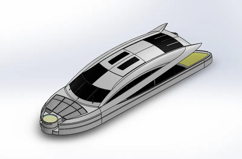
Superstructure:
- A superstructure is an upward extension of an existing structure above a baseline.
- The superstructure is a ship/ yacht is the part that emerges from the
- In this yacht superstructures like the front seat, middle seat,rear seat and cabin are modell
- The superstructure may be built in multiplelayer
- In this yacht single layer superstructures are used.
- Space for living accommodation,meeting room are provided inside superstructures.
Steps for modeling the Yatch SuperStructure:
- Insert the blueprint of the yacht ina new part.
- Create half of the superstructure by surface modelling and convert it into a solid
- Create a foundation tank on the front side of the superstruct
- Provide handle for on the surface of the foundation t
- Create steps in the front portion of superstructur
- Create glass window portion on the surface of the superstructure.
- Create a wiper part over the front wi
- Create a handle for the backside door of the superstructure.
- Create a surface on the foundation tank and provide appropriate transparency on i
- Apply colour to all the necessary surfaces.
- Rendered images of the yacht superstructure are shown below.
Feature used in SuperStructure:
- Sketch
- surface extrude
- sweep surface
- projection curve
- Reference plane
- fillet
- surface kint
- surface fill
- surface loft
- surface trim
- dome
- EXTRUDE CUT
- thicken
- chamfer
- extrude boss
- mirror
- apperance
Isometric view:
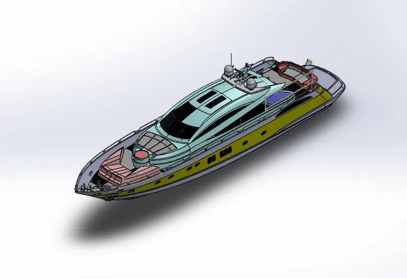
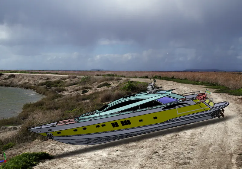
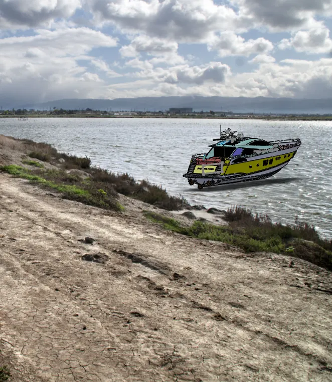
Assembly of all parts:
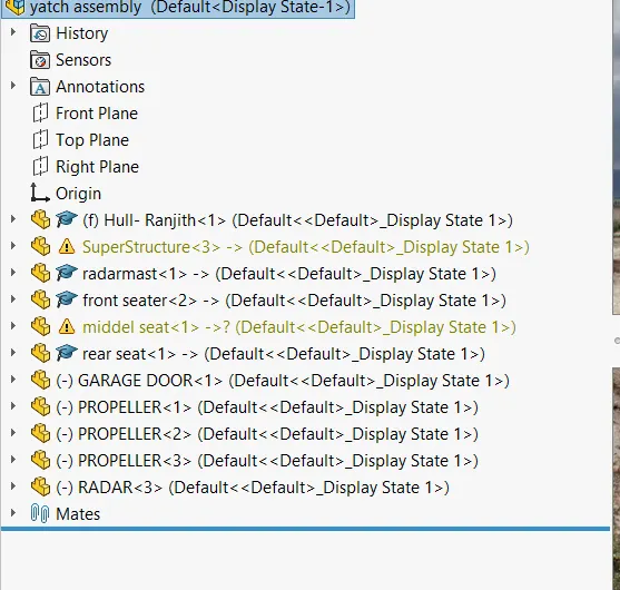
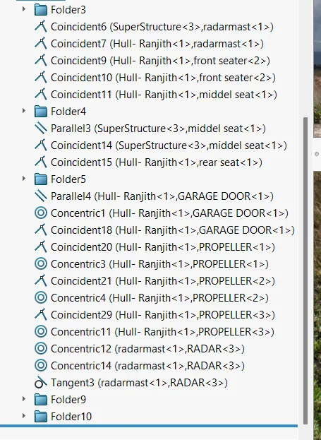
Feature tree plans: