Radar Mast & Final Assembly of Yacht
Radar mast
outputs:
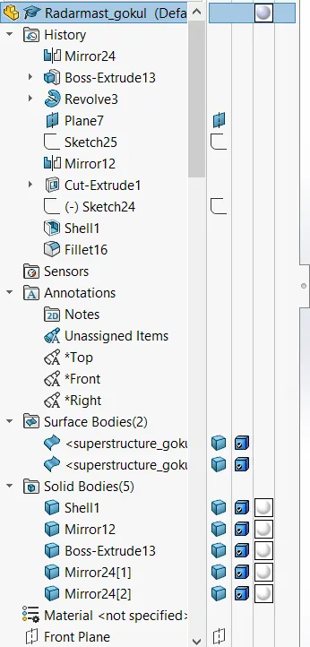
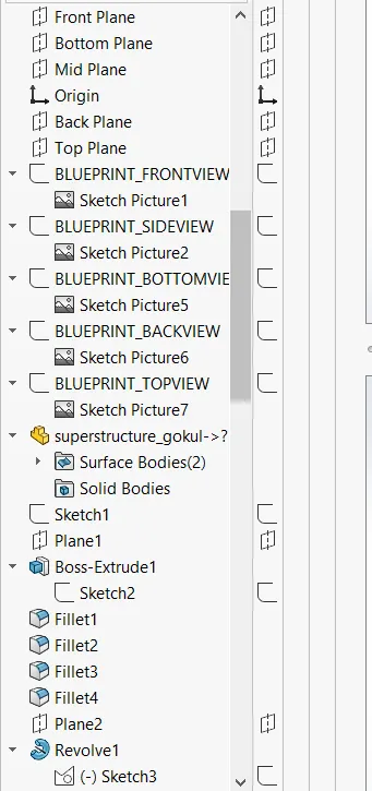
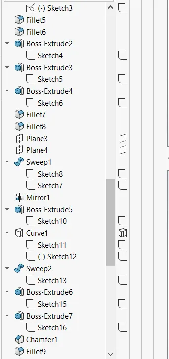
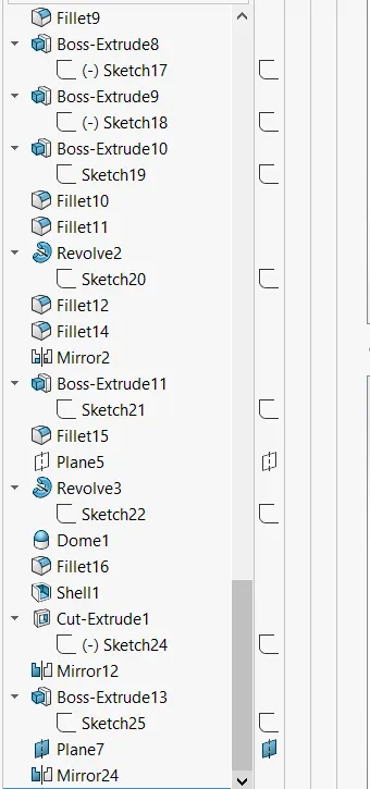
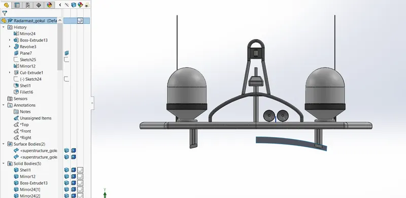
1. Front view
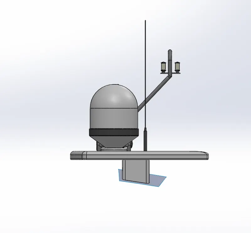
2. side view
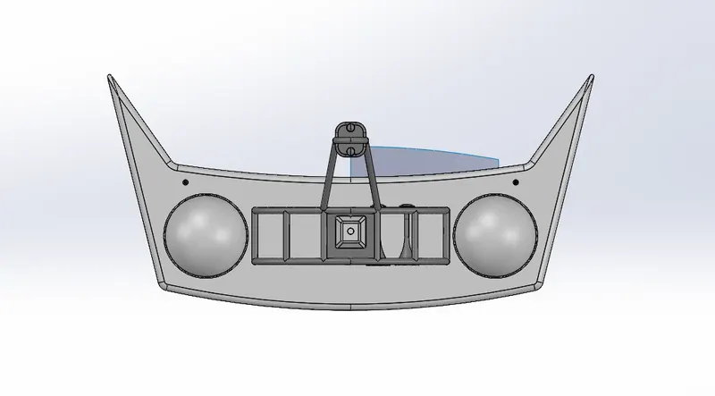
3. Top view
RADAR MAST AND ASSEMBLE THE YACHT
In this project we learn about the design of Yacht assembly with the help of SOLIDWORKS. In this we first learn to use the commands and then we draw parts. By using blueprint sketch, we get idea of sketching the parts and its dimensions. After designing all the parts we do assembly of Yacht. After assembly we add necessary decals, camera and do rendering of Yacht by using SOLIDWORK Visualization.
The components are:
- Hull
- Superstructure
- Front seat
- Middle seat
- Rear seat
- Propeller
- Radar
- Radar mast
- Garage door
Objective:-
- To learn the basic commands of SOLIDWORK.
- With the help of blueprint sketch we design all the parts of Yacht.
- Assembling all the parts in SOLIDWORK.
- Get the knowledge of concepts like decals, light and camera angle.
- Proper setting of image quality and getting realistic view with the help of photoview 360.
- Rendering of Yacht has done with help of solidworks visualization software.
Design approach:-
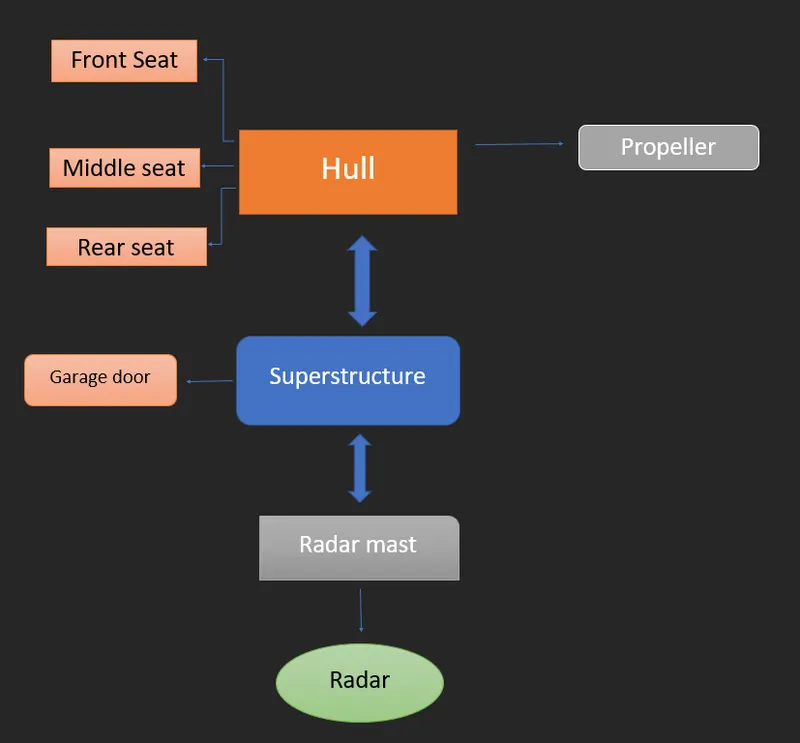
used in the Lets see what are the features and properties entire model to design different parts:
- Extrude boss
- Fillet
- Revolve boss feature
- Extrude cut
- Shell
- Linear pattern
- Mirror
- Reference geometry
- Projected curve
- Knit
- Surface loft
- Surface sweep
- Fill
- Surface Trim
- Surface extend
- Mate
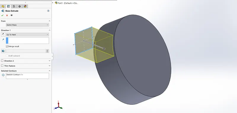
- Extrude boss:
The most basic feature from SOLIDWORKS is extrude boss. This feature needs a complete 2D sketch to convert 2D sketch into a solid body. When we exit the fully defined sketch we get the boss extrude option and a property manager window pop-up. Into the property manager we see from where the feature begins and where it will end that we need to add dimensions to it. It creates a complete solid body of any shape with closed entities. In this feature we can add dimensions to both the direction (direction 1 and direction 2) according to our need. We can use the direction if it is blind, midplane, from the vertex, etc. This is how we use this feature.
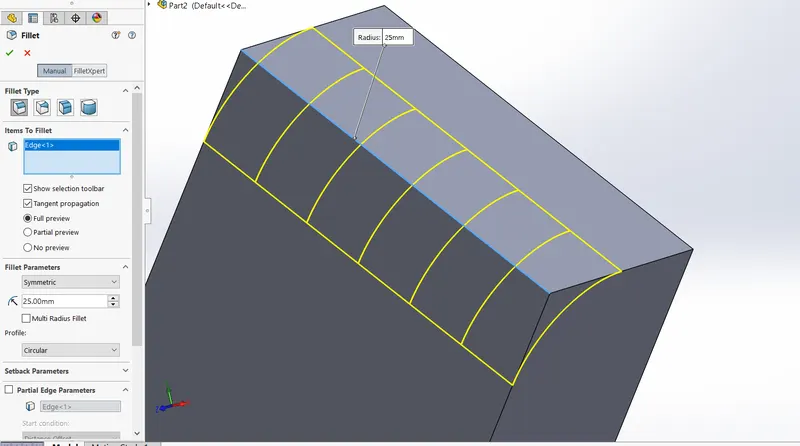
2.Fillet:
When we draw a solid part it is having some sharp edges. To give the roundness to those edges we add fillets. It makes the sharp edges or corners round shape of having different sizes or radius. The material can be added or removed according to conditions whether edges are internal or external. Fillets are used to solid bodies to hide the corners and edges and also it gives nice appearance to the part. Various types of fillets are used according to the given condition or it depends upon the part.
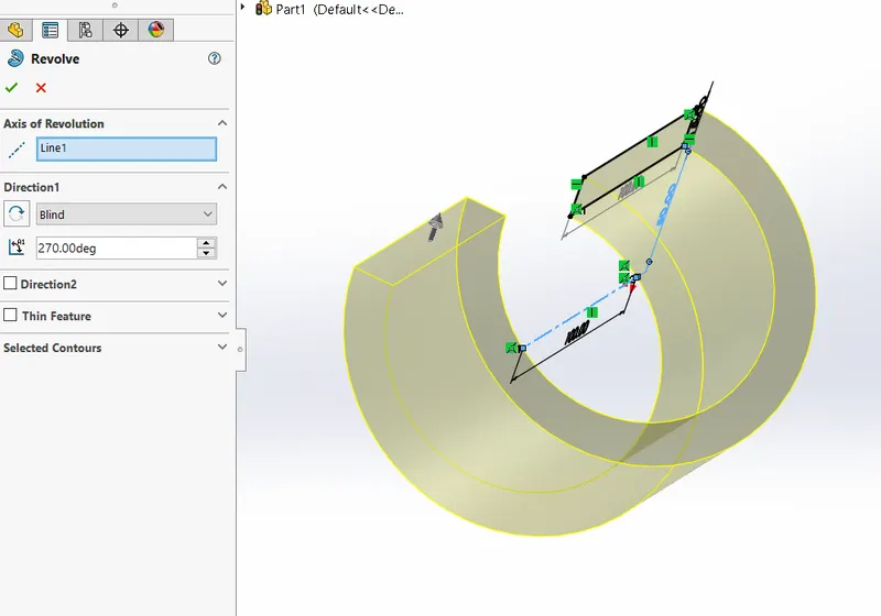
3. Revolve boss feature:
This feature works around an axis, by selecting axis of a sketch it adds a round material by revolving around that axis. If there is no axis we can select an edge of a sketch and it gives us appropriate geometry.
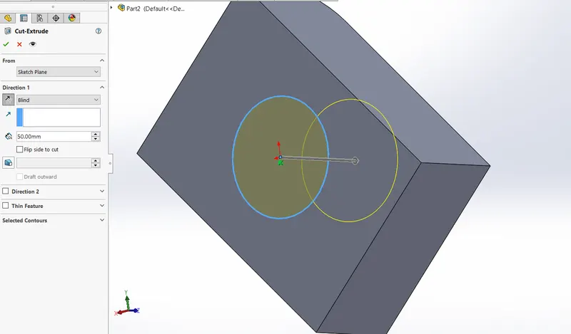
4. Extrude cut:
As the name implies, it cuts the geometry which we don’t need from the part or it can be used to give the desired shape to the sketch or solid part. When we draw sketch on the solid part and then we use extrude cut command it removes that part/surface.
5. Shell:
It is very handy tool in SOLIDWORKS. It gives some sort of idea that how inside geometry of a part will appear. In this tool we give inside thickness to the geometry and material removed from the body and it becomes hollow.
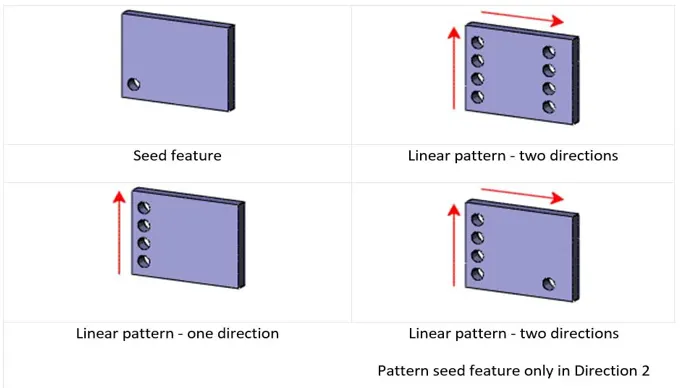
6. Linear pattern:
Linear pattern is used to create single sketch to use multiple times. The spacing, angles and path can be given in this feature to draw or create pattern. This feature spaced uniformly along one or two linear paths.
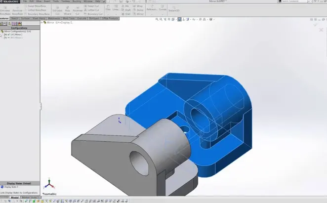
7. Mirror:
This feature creates copy of solid part. When this feature is applied it need plane or axis to mirror. Select the body which is to be mirror, select an axis or plane then apply feature and the mirrored part will get. Multibody parts: Apply feature to one or more multibody parts by selecting geometry pattern and using feature scope to choose which bodies should include the feature.
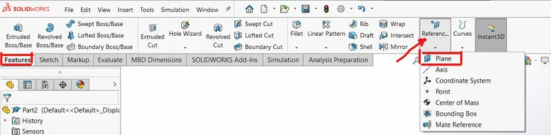
8. Reference geometry:
It defines the shape or form of a surface or a solid. This includes features such as planes, axes, co-ordinate system and points. This can be used according to need in a sketch.
Use of reference geometry example:
- Axis: If we want to pattern something and axis is not available by using reference geometry axis it gets easier to make pattern.
- Plane: If we need to sketch and there is need of plane by using reference geometry plane we can draw it and complete the sketch.
9. Projected curve:
The curve can be project by a sketch into a model to create a 3D curve. We can create multiple closed or open contour projected curves from a single sketch. Generally the curve can be intersection of two extruding surfaces. The curve which is created can be use as a path for the sketch of the part. Note: It do not create curve of an intersecting curves.
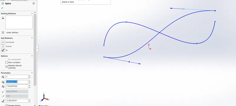
10. Knit:
Use of knit surface tool to combine two or more faces and surfaces into one. It create a solid body when the knit surfaces form a closed volume or leave as a surface body.
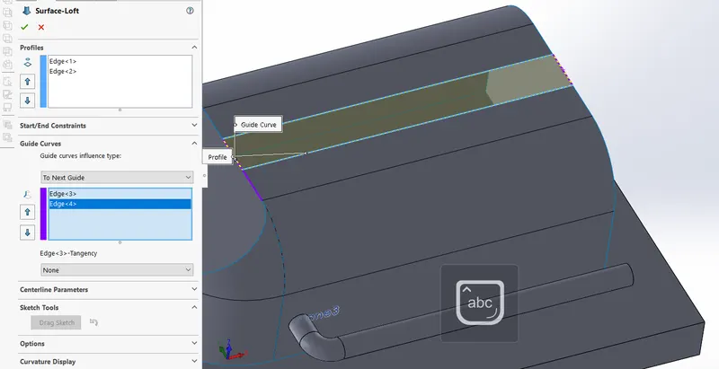
11. Surface loft:
The surfaces are generated by multiple 3D curves or existing edges creating smoot tangency between the selected curves.
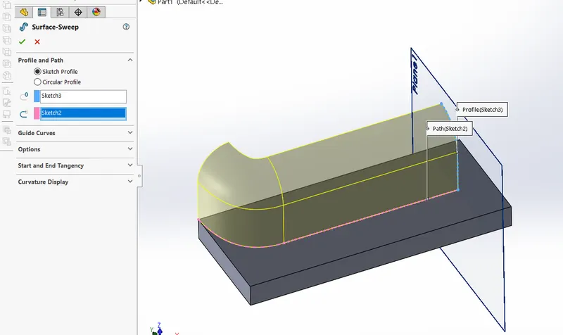
12. Surface sweep:
The surfaces are generated from a section curve positioned along a path.
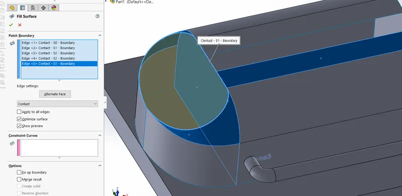
 13. Surface fill:
The surface fill feature constructs a surface path with any number of sides, within a boundary defined by existing model edges, sketches, or curves, including composite curves.
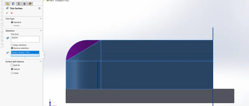
 14. Surface trim:
Surface trim primarily used to cut any material from a surface and provides 2 modes: standard and mutual.
15. Extend surface:
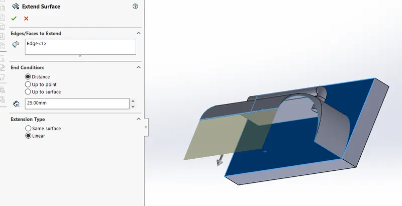
Extend surface is used to extend the surface which is already created. There are different options available on the extended surface. We can extend the surface as the same surface or we can extend the surface tangent to the surface.
16. Mate:
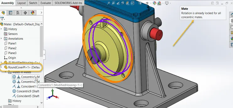
Mate creates geometric relationship between assembly and component. When we add mates, it defines the allowable direction of linear or rotational motion of component within its degree of freedom, visualizing the assembly’s behavior.
This feature includes:-
- Coincident mate: Coincident mate make two planar faces to become coplanar. This mate can move along one another but cannot be separated.
- Concentric mate: This makes two circular faces to become concentric and can move along the common axis.
- Tangent: This feature can be use between a face and plane to make tangent mate.
- Angular mate: This make angular relation between flat surface and the surface having some angle.
Now we have completed discussion of how the features work under solid works. Let us see the application of the features in the Yacht that we have built. We are going to discuss part by part as shown in the flowchart.
- Hull: A hull is the watertight body of a ship, boat, or flying boat. The hull may open at the top (such as a dinghy), or it may be fully or partially covered with a deck. A top deck may be a deck house and other superstructures, such as a funnel, derrick, or mast. The line where the hull meets the water surface is called the waterline.
Features used to create the Hull:
- Sketch
- Projected curve
- Boss Extrude
- Surface loft
- Shell
- Cut Extrude
- Fillet
- Mirror
- Pattern
- Split
- Knit
- Appearance
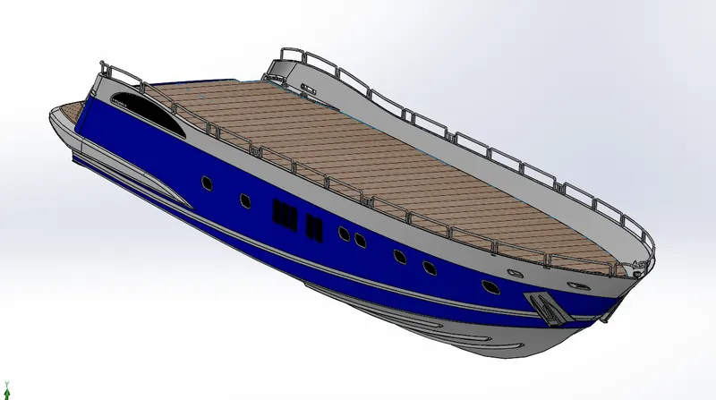
- Superstucture: A superstructure is an extended construction of any building or platform that rises above the rest of the building or platform in a distinct manner. Superstructure mean to add a construction to an already existing structure. In ships this is the name given to the part of the ship that emerges from the deck.
Features used to create the Superstructure:
- Sketch
- Surface extrude
- Surface loft
- Sweep
- Boundary surface
- Surface extend
- Surface trim
- Fillet
- Ruled surface
- Surface fill
- Knit
- Boss extrude
- Mirror
- Appearance
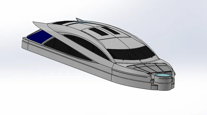
- Front seat: The front seat is placed on the front part of the hull.
Features used to create front seat:
- Surface sweep
- Surface extend
- Surface fill
- Surface loft
- Surface knit
- Chamfer
- Fillet
- Revolve
- Cut extrude
- Dome
- Appearance
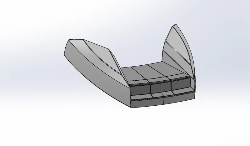
- Middle seat: The middle seat is placed under the superstructure.
Features used to create the middle seat:
- Sketch
- Boss extrude
- Cut extrude
- Fillet
- Mirror
- Appearance
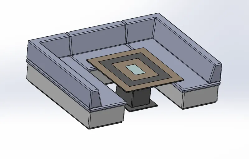
- Rear seat: The rear seat is placed at the back of the hull.
Features used to create the middle seat:
- Sweep
- Surface offset
- Surface trim
- Fillet
- Chamfer
- Split line
- Extrude cut
- Boss extrude
- Surface extend
- Appearance
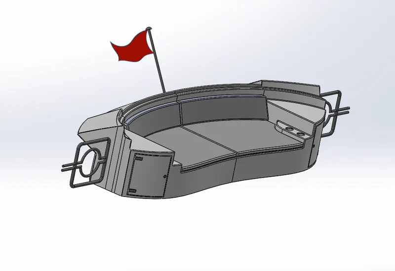
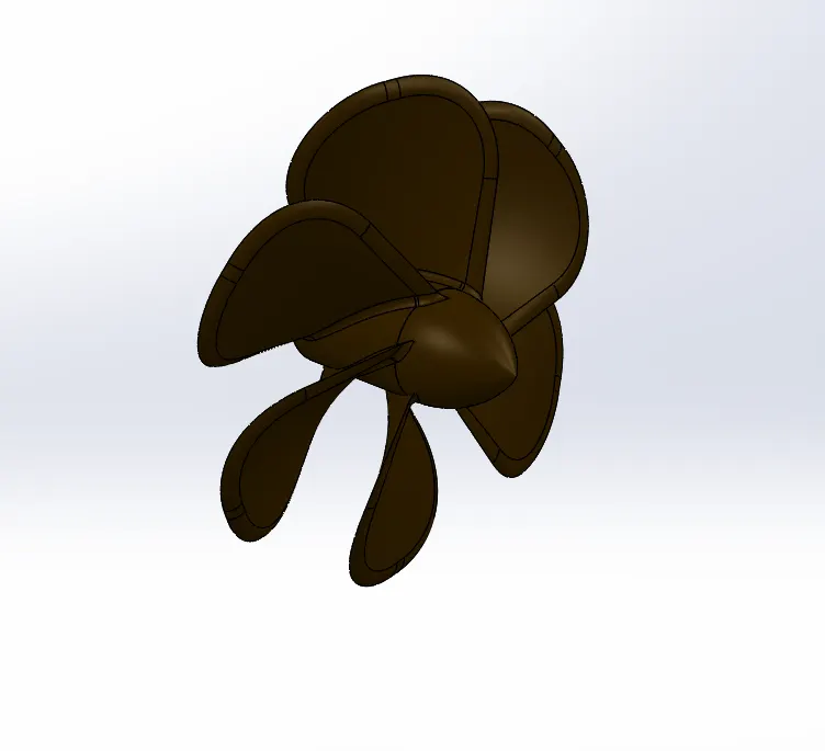
- Propeller: A propeller is a rotating fan like structure that is used to propel the ship by using the power generated and transmitted by the main engine of the ship. A ship an be fitted with one, two and rarely three propellers depending upon the speed and manoeuvring requirements of the vessel.
Features used to create the propeller:
- Sketch
- Boss revolve
- Boss loft
- Fillet
- Extrude cut
- Circular patten
- Appearance
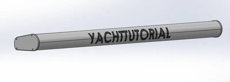
- Radar: Marine radars are X band or S band radars on ships, used to detect other ships and land obstacles, to provide bearing and distance for collision avoidance and navigation at sea. Radar is a vital navigation component for safety at sea and near the shore.
Features used to create the radar:
- Sketch
- Boss extrude
- Fillet
- Extrude cut
- Sketch driven pattern
- Mirror
- Appearance
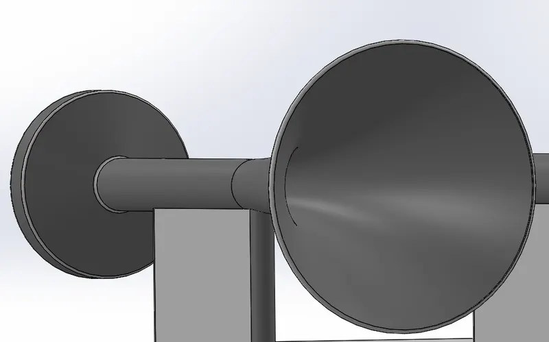
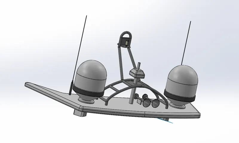
- Radar mast: The mast is a rangy spar arrangement that is elevated more or less vertically to the centreline of a ship. It has several purposes, including carrying derricks and giving fundamental height o the navigation light, salient yards, radio or radars, and scanner.
Features used to create the radar mast:
- Sketch
- Boss revolve
- Boss extrude
- Fillet
- Sweep
- Mirror
- Appearance
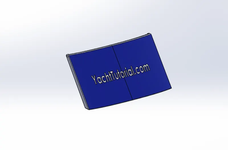
- Garage door: A garage door is a large door on a garage that opens either manually or by an electric motor. The garage door is used to close the garage part in the hull.
Features used to create the garage door:
- Extrude cut
- Shell
- Fillet
- Mirror
- Chamfer
- Mirror
- Appearance
Assembly:
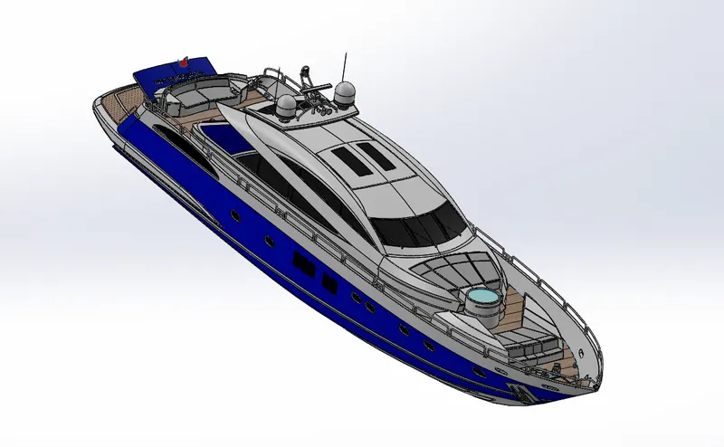
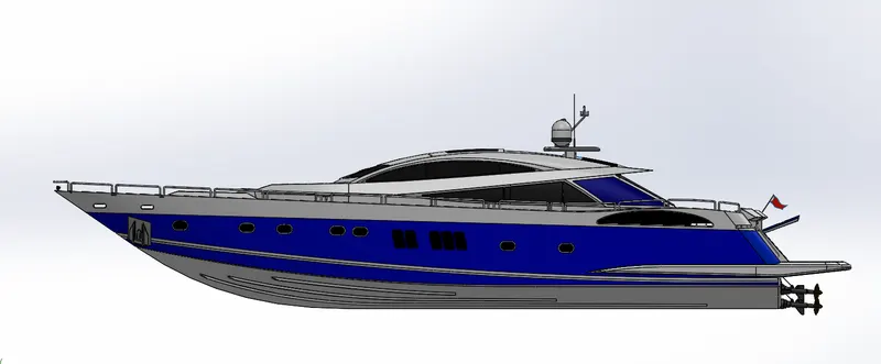
The modeled parts of the yacht are inserted in this assemble environment. The possible mate conditions are given to assemble the yacht.
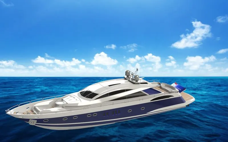
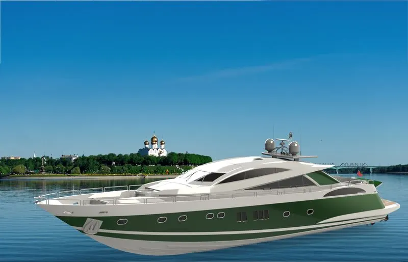
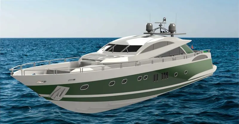
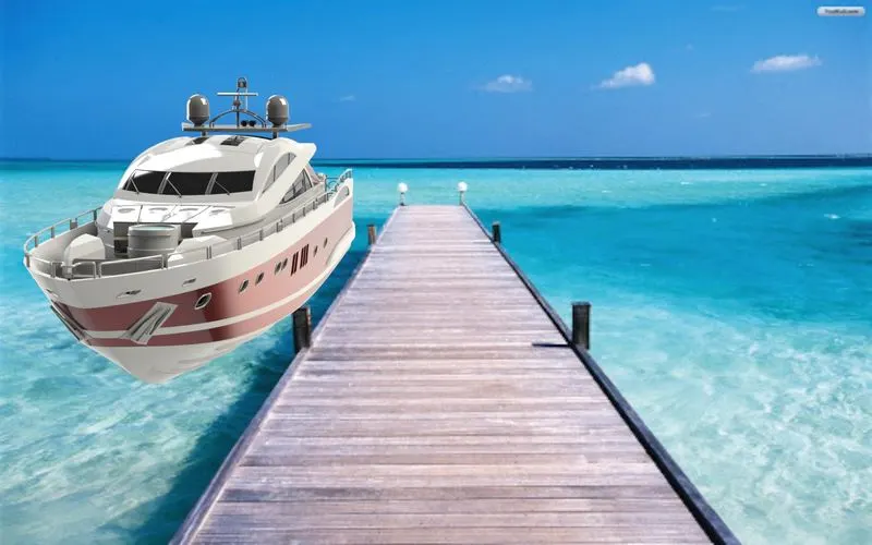
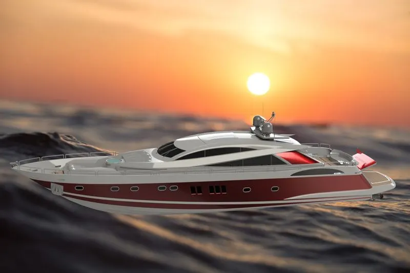
Rendering: The term rendering comes from the graphic world where a rendering is an artistic drawing of what a new structure would look like. In Computer Aided Design (CAD), a rendering is a particular view of a realistic image. By doing rendering of Yacht we get the idea that how it will look into the environment. This rendering is done in the SOLIDWORK Visualize software. By using PHOTOVIEW 360 we can add various camera views to the model, we can set various angles, direction, and can set appropriate distance to get the perfect camera view. In rendering we change color of Yacht parts, background images, brightness, rotation and various setting of Yacht. Including the resolution and setting number of passes we get more detail visual’s of Yacht.
Conclusion:
The parts of the yacht are modeled. The parts are inserted in the assembly environment and the yacht is assembled using the solidworks 2020 software. The photorealistic images are rended using the solidworks visualize.