Radar Mast & Final Assembly of Yacht
Final Assembly of Yacht
Objective:-
Design the individual components of a yacht and assemble them together by using solidworks.
Introduction:-
A yacht is a watercraft used for pleasure or sports. The term originates from the Dutch word Yacht, and originally referenced light, fast sailing vessels that the Dutch Republic navy used to pursue pirates and other transgressors around and into the shallow waters of the Low Countries.
Today's yachts are almost exclusively for leisure. A yacht is any sail or power vessel used for pleasure, cruising, or racing. The word often connotes luxury; however, luxury is not a quality necessary to meet the definition; nor is it always desirable. Many racing yachts are stripped-out vessels with a minimum of accommodations to lower weight. The term 'sailboat' or 'sail yacht' is used in America to differentiate from a 'powerboat' or 'power yacht.
Parts to model:-
- Propeller
- Radar
- Hull
- Garage door
- Front seat
- Middle seat
- Rear seat
- Superstructure
- Radar mast
- Assembly.
Over-all Flow chart:-
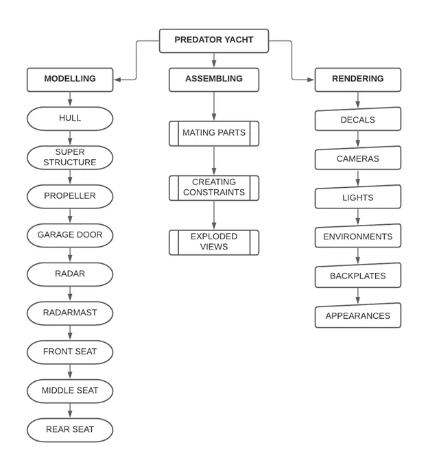
Flowcharts:-
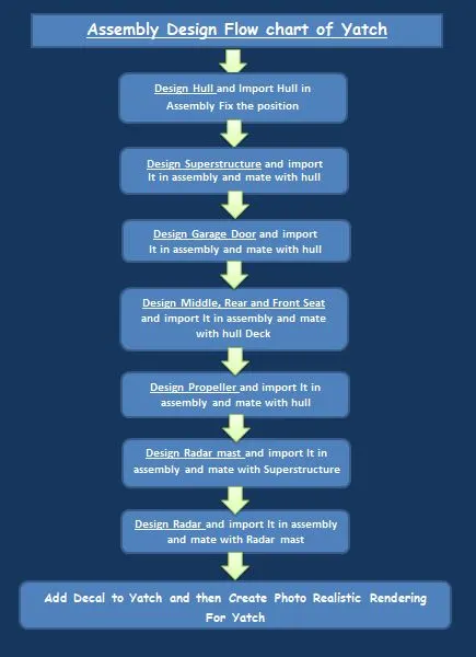
Description:-
1.propeller:-
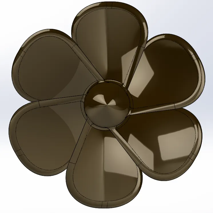
A propeller is a device with a rotating hub and radiating blades such as water or air.Propeller looks like a fan, it is placed such that it is submerged inside water. Propeller is the main component for the navigation of a yacht/ship, it receives power from the engine, it helps the yacht/ship move forward or backward by pushing the water in the opposite direction, for instance if the ship is moving forward the propeller pushes the water backward and vice versa.
Design:-
- Create a sketch using line & spline & apply revolve command.
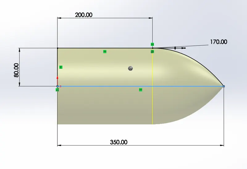
- Create a two rectangular sketches & apply solid loft command.
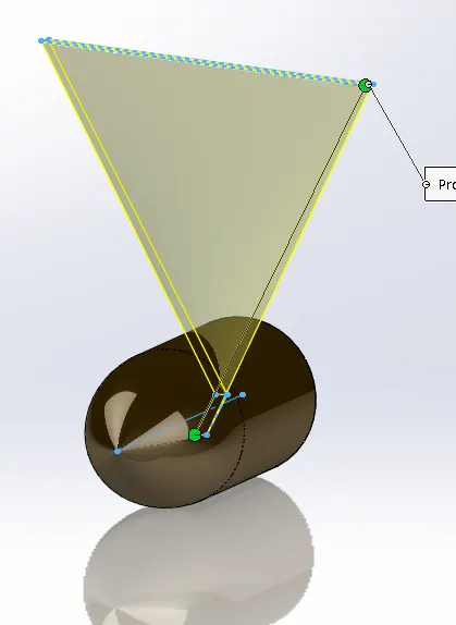
- Apply fillet to the blade
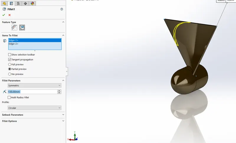
- Apply circular pattern to the blade.
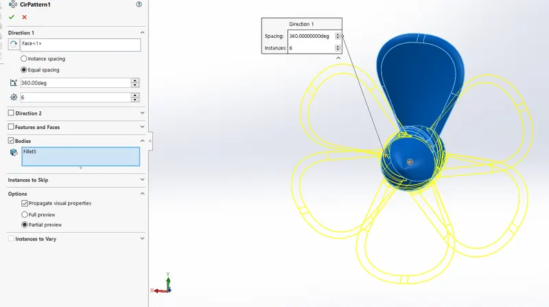
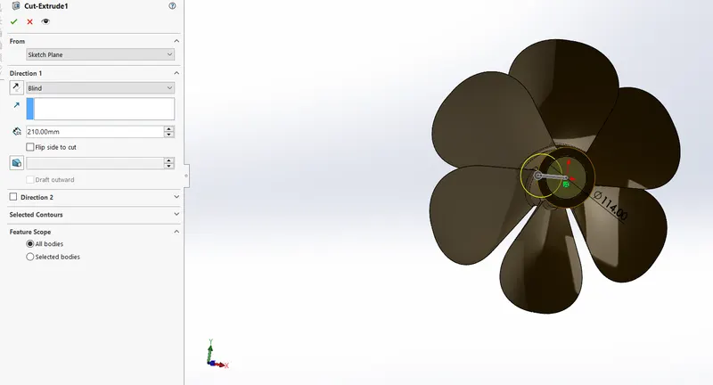
- Use extrude cut command to the cut the solid body.
2.Radar:-

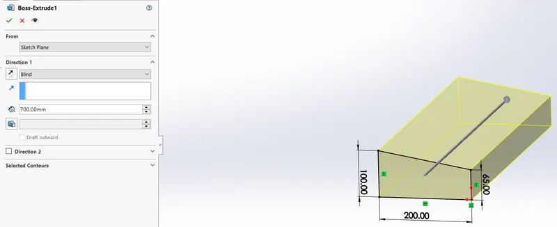
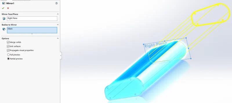
Radar is a device used for detecting objects. It is a very important device in any yacht/ship. It is mated with a part called radarmast and placed on the topmost part of the yacht.
Deaign:-
- Create a 2d Sketch & apply boss extrude command
- Mirror the body & create a circular slot
3.Blueprint Image:-
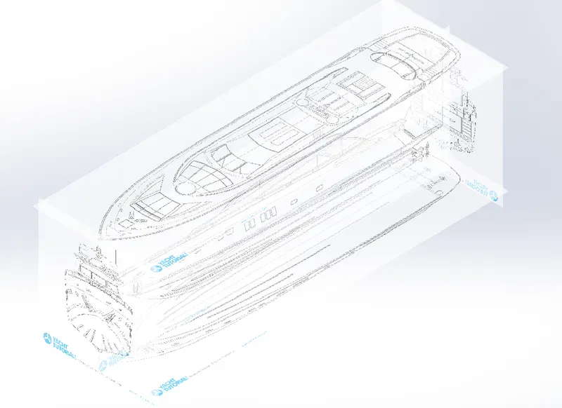
- Select a Plane & select a 2d drawing option & go to Tools- Sketch tool-Sketch Picture.
- Browse the Image & change the dimensions as per requirement & use transparency tab & choose full image for convenient sketching & name the views.
- Repeat the above steps & name it as Front view, side view, Top view, Back view.
- change the names of the planes as front plane, bottom plane & mid plane & Arrange the blueprints in a sequential order.
Image:-
4.Hull:-
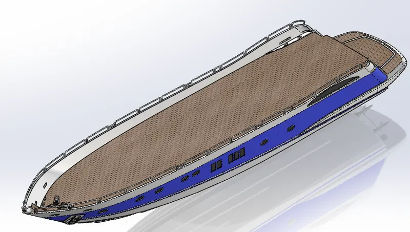
A hull is the watertight body of a ship or boat. The hull may open at the top and it may be fully or partially covered with a deck. Atop the deck may be a deckhouse and other superstructures, such as a funnel, derrick, or mast. The line where the hull meets the water surface is called the waterline.The Design of Hull involves preparation of outer shell surface and the deck surface. The outer shell is drafted with the required curves initially and are extruded and lofted, to obtain the required surface the cures are drawn on different planes and they are projected so that the required curvature is obtained in between the planes
Design:-
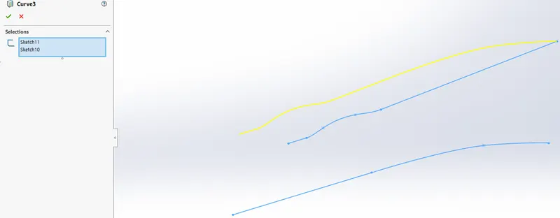
- Curve Projection:- It is one of the option in Solid works tool which gives us the output cure for the two curves/lines drawn on different planes, this is the intersection path where the two extruded surfaces meet.
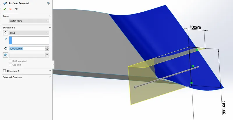
- Surface Extrude:- It is used to form the surface bodies where the thickness is line thick.
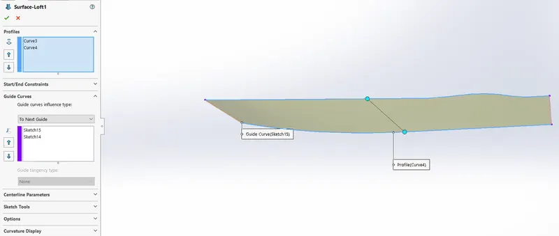
- Surface Loft:- Loft is the option used to prepare very difficult surfaces formed with the help of 4 different curves drawn on different planes.
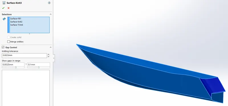
- Surface Knit:- It helps to eliminate the minor gaps exist between the two surfaces and join them together as like a single surface. This option works only for surfaces not for solid bodies.
- Sweep: - It helps to produce solid tube along the guided curve/line path.
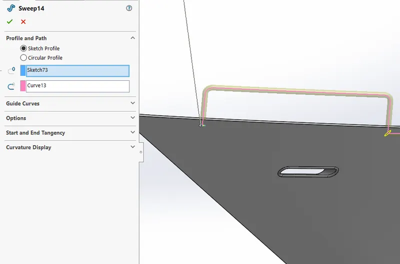
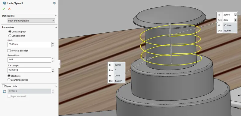
- Helix/spiral:- it is used to create any springs it screw treads as this option contains pitch or height and revolutions which describes how many rings with gap between them.
5.Garage door:-
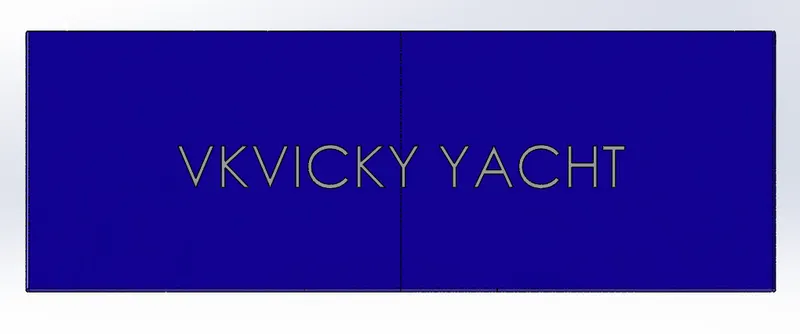
This part is modelled in a solid model which was saved when split command was used during modelling hull. The part is retrieved and is used for the construction of the garage door. It is a symmetric model, therefore the other half is mirrored. The name is engraved using text and cut extrude (offset from surface) commands.
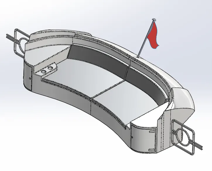
6.Front,Middle,Rear Seats:-
Front Seats
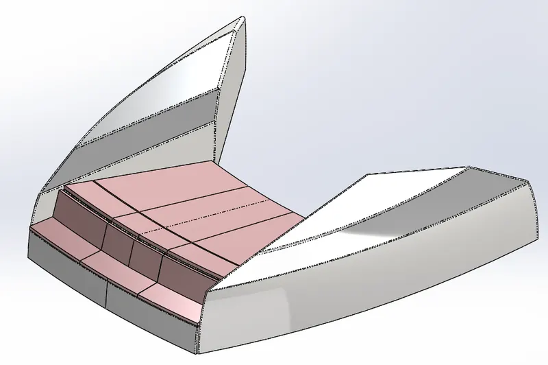
Middle Seats
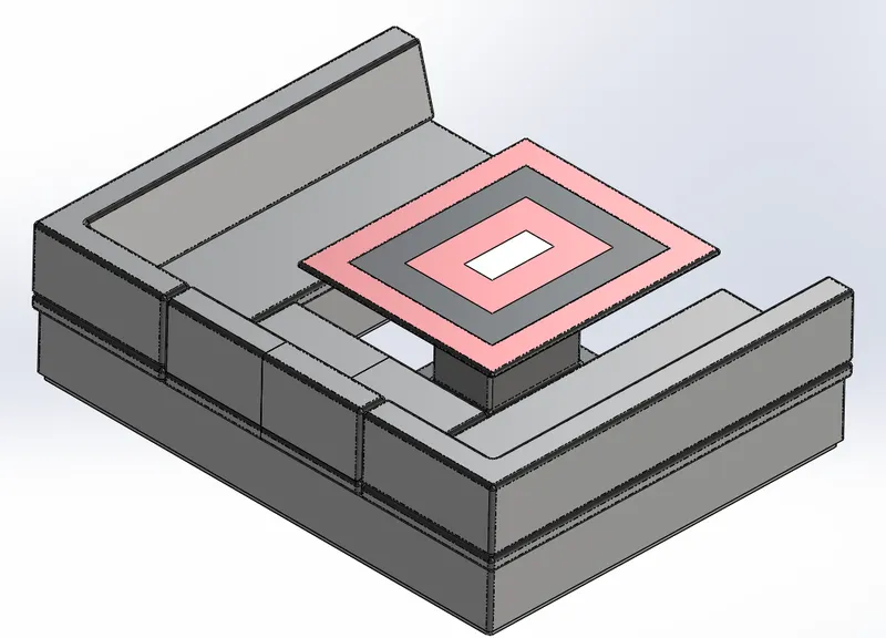
Rear Seats
7.Superstructure:-
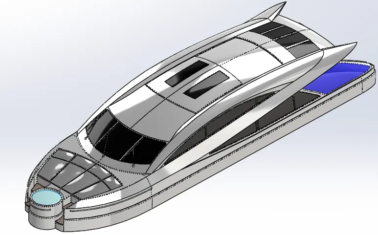
It is placed on the top of the hull. It is also a symmetric model therefore it is enough to model one half so that the other half could be mirrored. It is modelled in a way similar to hull, the model is started in surface modelling with a deck surface imported from hull as reference. The desired surfaces are modeled and the surface model is converted into solid and proceeded with solid modelling.
- The most complicated part of the whole yacht design is its superstructure which sits on top of the deck surface.This super structure also designed with the help of the imported blue print top, front and side views as shown in the below picture.Initially the wall of the super structure is created by drawing a line on the bottom plane along with the curvature using the spline option and making it constrained using proper dimensions and being surface extruded in the feature manager tab.
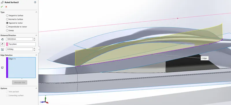
- Ruled Surface: - It is used to obtain the extrude surface perpendicular to the plane of reference and the added advantage of Ruled surface is that the surface can be tilted with an angle as prompted in the tool along with the length.
8.Radar mast:-
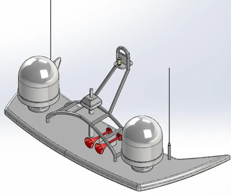
- Marine radars are X band or S band radars on ships, used to detect other ships and land obstacles, to provide bearing and distance for collision avoidance and navigation at sea. They are electronic navigation instruments that use a rotating antenna to sweep a narrow beam of microwaves around the water surface surrounding the ship to the horizon, detecting targets by microwaves reflected from them, generating a picture of the ship's surroundings on a display screen.
- Radar is a vital navigation component for safety at sea and near the shore. Captains need to be able to maneuver their ships within feet in the worst of conditions and to be able to navigate "blind", when there is no visibility at night or due to bad weather. In addition to vessel-based marine radars, in port or in harbor, shore-based vessel traffic service radar systems are used by harbormasters and coast guard to monitor and regulate ship movements in busy waters.
- Radars are rarely used alone in a marine setting. A modern trend is the integration of radar with other navigation displays on a single screen, as it becomes quite distracting to look at several different screens. Therefore, displays can often overlay an electronic GPS navigation chart of ship position, and a Sonar display, on the radar display. This provides a combined view of surroundings, to maneuver the ship.
Assembly:-
To Assemble a SolidWorks Model into an Existing Assembly
- 1. Open an assembly.
-
2. Click Component > Assemble > Assemble. The Open dialog box opens.
- 3. Select SolidWorks Part (*.sldprt) or SolidWorks Assembly (*.sldasm) in the Type box.
- 4. Select a part or assembly file from the list of files displayed.
- 5. Select Import to import the SolidWorks part or assembly and assemble it as an imported component in the existing assembly. The Import New Model dialog box opens.
- 6. Select an import profile from the Profile list to replace the profile in use. You can click Details if you want to customize the profile settings in the import profile editor, SolidWorks — Import Profile. The Enable ATB option is selected by default in the import profile and the Import New Model dialog box.
- 7. Click OK in the Import New Model dialog box. The Component Placement tab opens.
- 8. Accept the default coordinate system location or select a coordinate system to position the geometry.
- 9. Package the imported part or subassembly component into the assembly or add associative placement constraints.
-
10. Click on the Component Placement tab. The SolidWorks part or subassembly component is imported and assembled in the assembly model. The import log file is automatically generated in the working directory.
Design:-
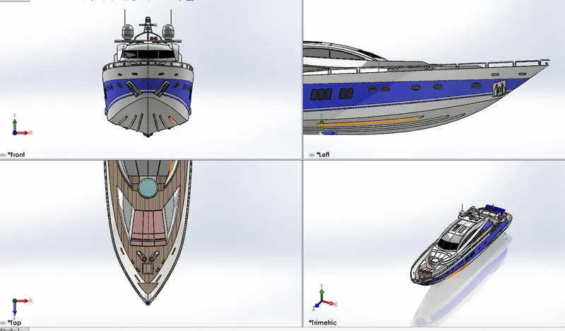
Isometric View:-
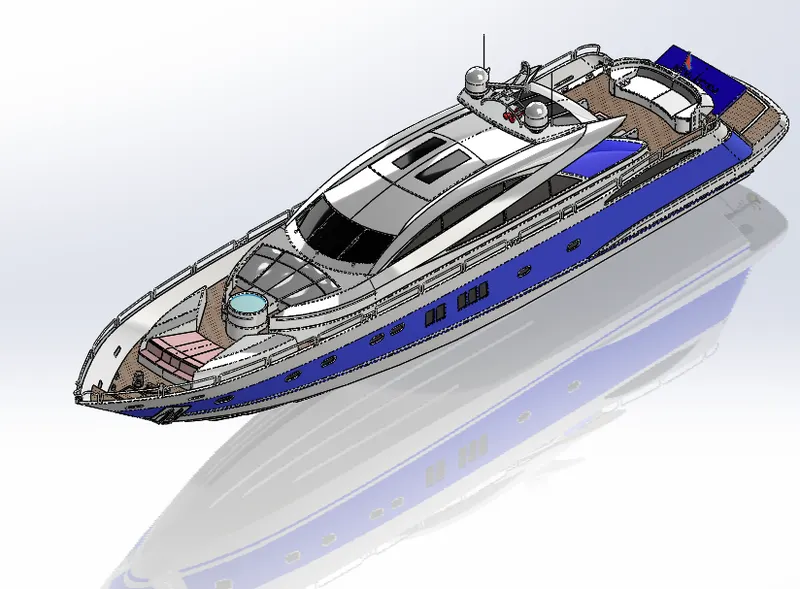
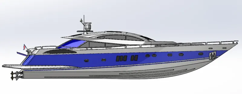
Side View:-
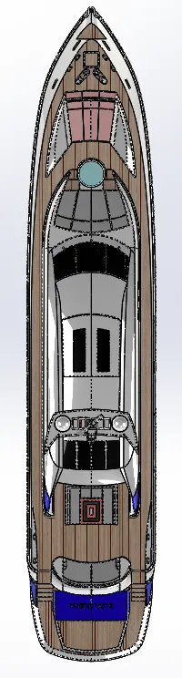
Top View:-
Front View:-
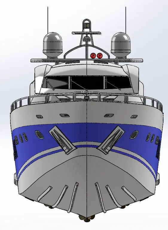
Over-all View:-
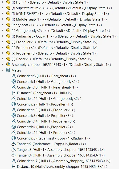
Feature Trea:-
Rendering:-
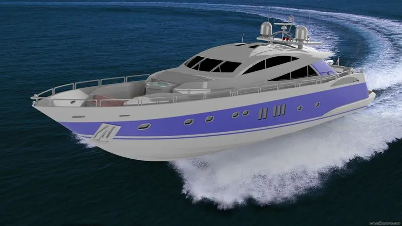
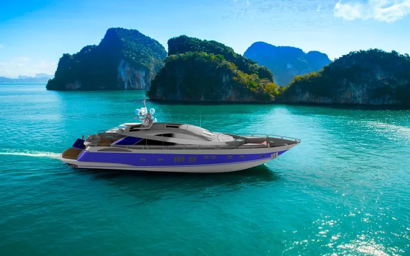
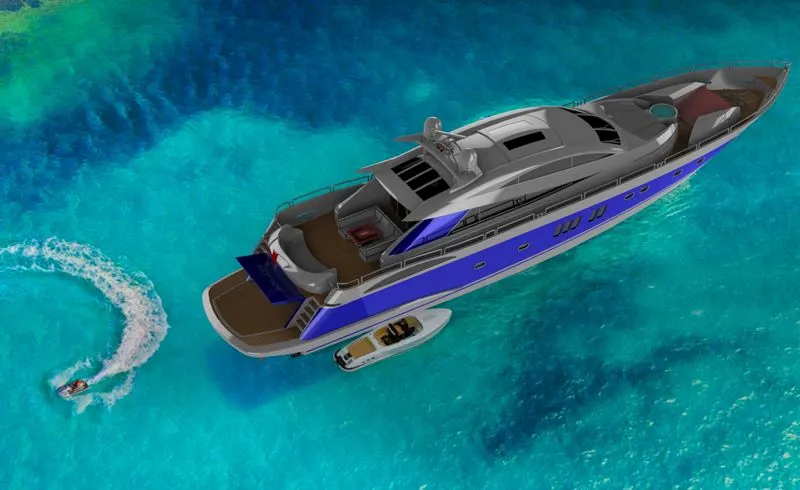
Rendering is the automatic process of generating a photorealistic or non-photorealistic image from a 2D or 3D (or models in what collectively could be called a scene file) by means of the computer programs. Also, the results of displaying such a model can be called a render. A scene file contains objects in a strictly defined language or data structure; it would contain geometry, viewpoint, textures, lighting, and shading information as a description of the virtual scene. The data contained in the scene file is then passed to a rendering program to be processed and output to a digital image or raster graphics image file. The term "rendering" maybe by analogy with an "artist's rendering" of a scene.
Without backpalte Image
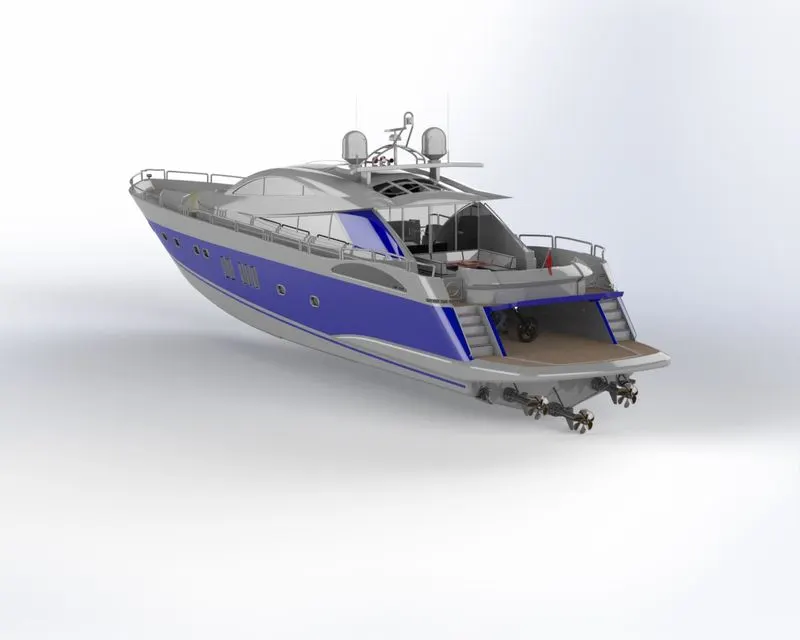
With backplate Image
Conclusion:-
From this project we learn that various techniques & commands the step we apply are so simple and it can be applied to any products for further modification.finally yacht design and rendering done properly.