Radar Mast & Final Assembly of Yacht
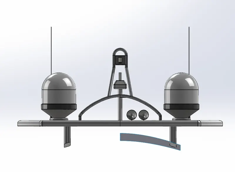
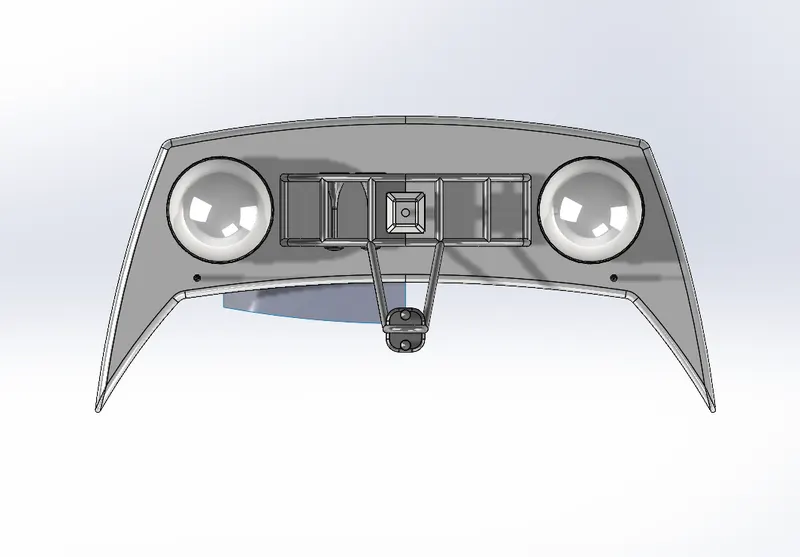
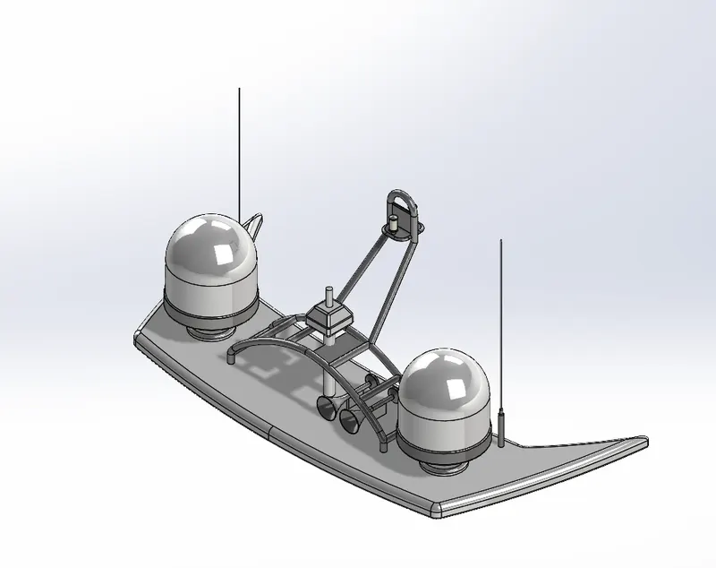
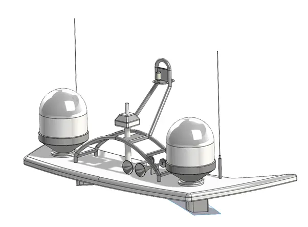
Radar mast
front view
top view
isometric view
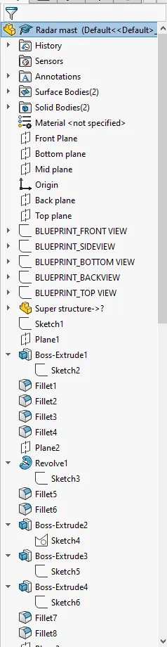
DESIGN AND ASSEMBLY OF SUNSEEKER YACHT USING SOLIDWORKS.
INTRODUCTION
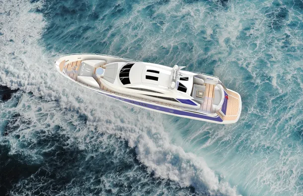
The report explains the detailed modelling of yacht using SolidWorks and rendering to portrait the realistic image using SolidWorks Visualise. Modelling of sunseeker yacht involves individual designing of each component and assembled to build a final model.
The Main components to design individually for assembly are:
- Propeller
- Radar
- Hull
- Garage door
- Front seat
- Middle seat
- Rear seat
- Superstructure
- Radar mast
This report mainly focuses on the surface modelling and the new features that involves to design engineered surfaces that involved in yacht. These individual components at last assembled to form a yacht and rendering is done to represent the yacht in real time environment using photo 360 and SolidWorks visualise. By applying different types of environments to the model to visualise and see the model in real time scenarios.
Design Approach:
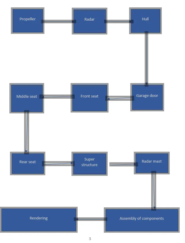
The below flowchart explains how the designing of the components will go in sequence.
Modelling of Propeller:
The vehicles which are moving on the roads or on the land need tyres or any rolling parts and in contact with land to produce frictional force also accelerating force at the same time. But when coming to the vehicles that are moving in air or water requires propellers to create thrust force.
Propellers consist of blades which are aligned in certain angle on the rotating shaft. And it works mainly on Newtons third law of motion and Bernoulli’s principle. In addition, depend on the accelerating force we required, and the type of load number of propellers vary. So, for this yacht we need three propellers.
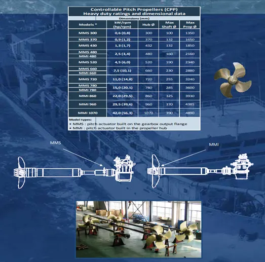
Usually, controllable pitch type of propeller is used for these types of yachts.
Design of propeller starts with the modelling of the rotating shaft.
The features involved are
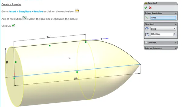
Revolve Boss/base: By using centerline as reference, it adds the or remove material for selected contour. We can apply revolve for multiple intersecting profiles and it does not lie on the centerline. Moreover, the selected profile must be 2D sketch, but the axis of revolution can be a 3D sketch.
Same as extrude boss revolve features can provides the several parameters which controls the revolve by property manager.
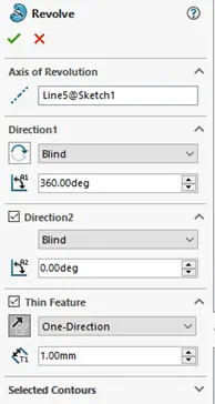 Axis of revolutio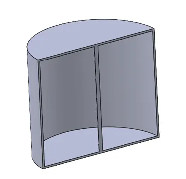
n which allows the feature to revolve around the specified axis, it can be a centerline, line, or edge (must be a straight line).
Direction 1 specifying the feature to revolve in one direction by revolve type.
Blind (allows to give an angle)/ up to vertex (until the given vertex or point)/ up to surface (until the selected surface or face)/ offset from surface (end of revolution up to distance from the selected surface)/ mid-plane (controlling both clockwise and anti-clockwise directions from the sketch plane.
Thin feature used to create a thin wall with a given distance from the axis of rotation.
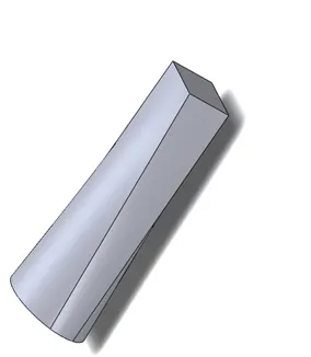
Loft boss/ base: Loft boss is similar like swept boss, but the difference is the starting and end profiles of the part are different and it provides more options than sweep to refine the shape.
To create a loft feature we need a minimum of two profiles on planes separated apart. If the profiles are open, then we can create a lofted surface otherwise a closed one. By accessing the property manager, we can create the lofted shape in more desired manner. During the creation of the lofted feature, there are some connecting points between two profiles, by adjusting them we can achieve the synchronization of lofted shape and these connecting points are joined by polylines.
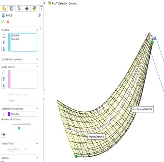
The path that followed from starting profile and the ending profile can controlled by centerline parameter, but the end points of the centerline are coincidence with the profiles. Also, we can insert lofted section between the profiles to enhance the shape and tangency.
By using loft feature, we are modelling the single blade by creating the plane at 360mm from the top plane and sketching a rectangle on the new plane.
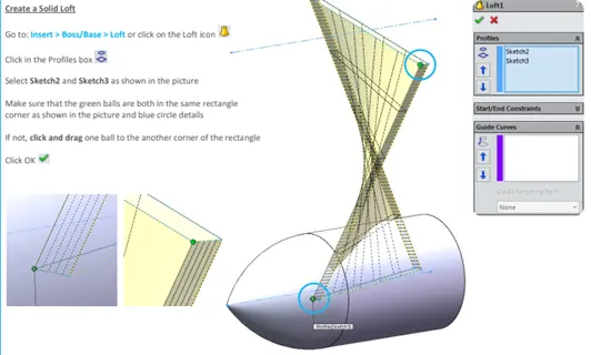
After creating the profile of blade, applying fillet feature with radius of 135mm at outer edge.
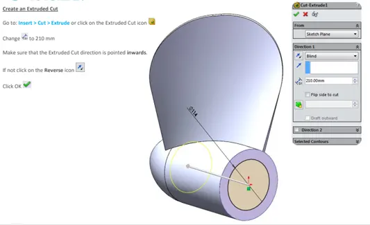
Then to connect propeller to the rotating shaft, a hollow feature is generated with help of extrude cut.
Now, by using fillet feature to round up the sharp edges of the blade at both top bottom with a fillet radius of 30mm as outside edge and 10mm for the inner edge.
Circular pattern: It allows to create similar features or faces or bodies by considering any center point as reference in circular manner. Now, by using this feature we are creating the blades in circular pattern.
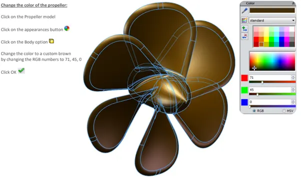
At last, changing the color of the body to custom brown with RGB numbers as 71, 45, 0.
Modelling of radar:
A mandatory aid to navigation, the radar is used in identifying, tracking (with integrated ARPA) and positioning of vessels (including ones own vessel) among other things in order to adhere to the COLREGs so as to safety navigate a ship from one point to another.
The marine radar is classified under the x-band (10 GHZ) or S-band (3 GHZ) frequencies. The x-band, being of higher frequency is used for a sharper image and better resolution whereas the S-band is used especially when in rain or fog as well as for identification and tracking.
In modelling of the radar, the features involved are:’
- Boss-extrude
- Fillet
- Cut extrude
- Sketch-pattern
- Mirror
- Split line
Extrude boss/base: Extrude is feature used to add the material for sketch, If the sketch is closed one it forms a solid body otherwise a surface. In detail, extrude feature is controlled by a property manager which gives access to additional parameters that controlling this feature and allows a desired extrude you want.
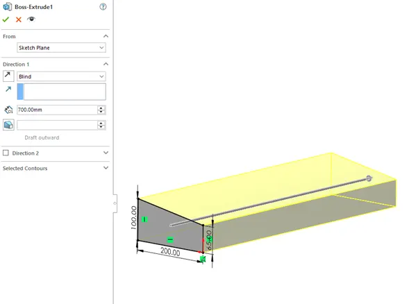
After extruding the base filleting the edges with radius of 46mm as large fillet radius, 20mm and 30mm as smaller radius. Then, extruding the extreme two edges with 10mm thickness.
Sketch driven pattern: Using sketch points within a sketch, you can specify a feature pattern. The seed feature propagates throughout the pattern to each point in the sketch. You can use sketch driven patterns for holes or other feature instances.
To build the sketch driven pattern:
Open a sketch on the face of a part, then create a seed feature on the model.
Click Point or tools > sketch entity > point and add multiple sketch points to represent the pattern you want to create, based on the seed feature. Then close the sketch. Then, click on the sketch driven pattern (feature toolbar) or insert > pattern/mirror > sketch driven pattern and for the reference select the sketch we created.
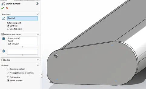
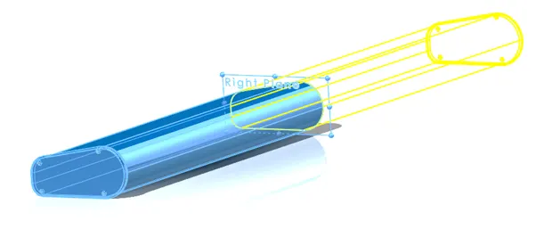
Mirror: Mirror is a very power tool in SolidWorks to save lot of time on parts which are symmetrical to the axis. We can mirror by selecting plane or face or axis in 2-Dsketching. In 3-D modelling features, surfaces and bodies can mirror with reference to plane or surface also can merge bodies together. Lastly, knit surface feature in mirroring allows to combine the mirrored surface when working with surface modelling.
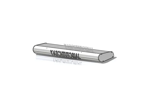
Split line: The Split Line tool projects an entity (sketch, solid, surface, face, plane, or surface spline) to surfaces, or curved or planar faces. It divides a selected face into multiple separate faces. You can split curves on multiple bodies with one command.
By using this command, we can project the annotations and other surfaces on the desired part.
Now, the next step is modelling of the hull, the modelling involves setting up the reference like blueprint at the background for easy modelling and understanding of the design, for this setup we need to import the images of the blueprint from the tools> sketch tools> sketch picture. Then import the respective images for the respective planes as shown in below figure.
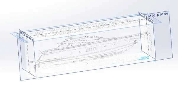
Modelling of the hull:
The modelling of the hull involves sketching the complex shapes by using the projected curves, then by combining the curves with loft features to create the solid body with complex engineering shapes.
Projected curves: Projected curve are 3D curves generated by projected planes from 2D sketches. The main concept of projected curve is, every 3D sketch can projected on to the vertical and horizontal plane and is used to create the complex shapes. It can create by sketching a 2D sketch on different planes by projecting them. To visualize better, projected curve is an intersection of two extruded surfaces. Mainly the start and end points of both 2D sketches must be same and there should no intersection in curves.
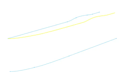
Then projecting the other sketches to create the second curves to join. Then by applying the loft feature to create the lofted surface by joining the composite curves sketches.
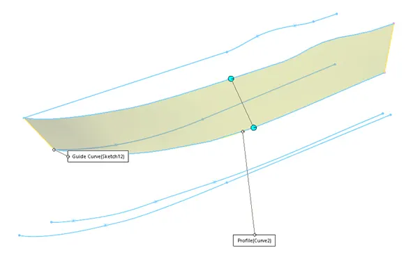
So, the modelling of the hull involves repetitive use of the surface loft wherever we need to create the shapes, also a perfect model will obtain by combining the other surface features like surface trim, surface fill and surface knit, so, we will discuss these features in detail.
Surface trim:
You can use a surface, plane, or sketch as a trim tool to trim intersecting surfaces. You can also use a surface in conjunction with additional surfaces, as mutual trim tools. Trim surface includes the following options:
To trim a surface:
- Create two or more surfaces that intersect at one or more points, or create a surface that intersects with a plane or has a sketch on its face.
- Click Trim Surface on the Surfaces toolbar, or click Insert > Surface > Trim.
- In the Property Manager, under Trim Type, select a type:
- Standard. Trims surfaces using surfaces, sketch entities, curves, planes, and so on.
- Mutual. Trims multiples surfaces using the surfaces themselves.
- Under Selections, choose from these options:
- Trim tool (available with Standard selected under Trim Type). Select a surface, sketch entity, curve, or plane in the graphics area as the tool that trims other surfaces.
- Surfaces (available with Mutual selected under Trim Type). Select multiple surfaces in the graphics area for Trimming Surfaces to use to trim themselves.
- Select a trim action:
- Keep selections. Retains the surfaces listed under Pieces to Keep. Intersecting surfaces not listed under Pieces to Keep are discarded.
- Remove selections. Discard the surfaces listed under Pieces to Remove. Intersecting surfaces not listed under Pieces to Remove are retained.
- Select surfaces in Pieces to Keep or in Pieces to Remove , based on the trim action.
- If you selected Mutual Trim, Preview optionsare available. Select one of the following:
|
Show included surfaces |
Displays the regions that you are including as surfaces. All other surfaces are hidden. |
|
|
Show excluded surfaces |
Displays the surfaces that you are excluding as transparent. All other surfaces are hidden. |
|
|
Show both included and excluded surfaces |
Displays both included and excluded surfaces. Excluded surfaces appear transparent. |
- Under Surface Split Options, select an item:
- Natural. Boundaries extend tangent from the ends of the Trim tool.
- Linear. Boundaries extend from the Trim toolendpoints to the nearest edge.
- Optionally, select Split All.
- Click ok.
Surface fill: The Filled Surface feature constructs a surface patch with any number of sides, within a boundary defined by existing model edges, sketches, or curves, including composite curves.
You can use this feature to construct a surface to fill a gap in a model. You can use the Filled Surface tool in these cases:
- Correct a part that does not import correctly into SOLIDWORKS (where there are missing faces).
- Fill the holes in a part used for core and cavity molding.
- Construct a surface for industrial design applications.
- Create a solid. Include features as separate entities, or merge those features.
To create a filled surface, click Filled Surface on the Surfaces toolbar, or click Insert > Surface > Fill, set the Property Manager options, and click OK
Surface knit:
Use the Knit Surface tool to combine two or more faces and surfaces into one.
Note the following about knit surfaces:
- Edges of the surfaces must be adjacent and not overlapping.
- Surfaces do not need to be on the same plane.
- Select the entire surface body, or select one or more adjacent surface bodies.
- Knit surfaces absorb the surface bodies you used to create them.
- Create a solid body when the knit surfaces form a closed volume, or leave as a surface body.
- Select Merge entitiesto merge faces with the same underlying geometry.
- Select Gap Controlto view the gaps or modify the knitting tolerance.
Chamfer:
The chamfer tool creates a beveled feature on selected edges, faces, or a vertex.
To create a chamfer:
- Click Chamfer (Features toolbar) or Insert > Features > Chamfer.
- Under Chamfer Parameters, select an item and set parameters.
- Click .
By using this features we completed the modelling of the hull.
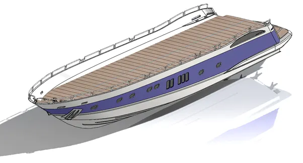
Modelling of the Garage door:
Garrage door in yacht used to store the machineries or the automobiles etc. usually these garage doors are operated by electric motors. In addition, for small yachts, the door with single frame that tilting up and down, in similar for larger yachts the door is combination of frames that joined by hinges for folding.
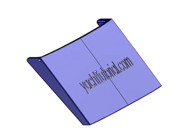
The features used to model is already used for other models.
Modelling of the superstructure:
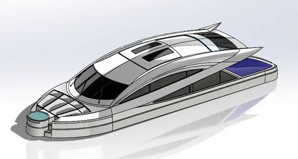
The superstructure is a complex part is used for accommodations and living, so it involves different complex shapes that designed using surface modelling and then knitting all the surface to create the solid model. The modelling starts with surface sweep.
Surface sweep: The surface sweep is similar to the solid sweep by sweeping the open sketch along the desired path to create the required surface.
Ruled surface:
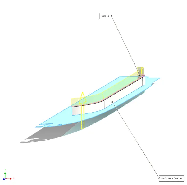
The Ruled Surface command creates surfaces that extend out in a specified direction from selected edges.
Examples of how you can use ruled surfaces:
- Add tangent extensions to complex surfaces
- Create drafted sidewalls
- Replace non-drafted surfaces on imported models with drafted surfaces (using the Taperedor Sweep type)
- Create parting and interlock surfaces
Property manager for ruled surface:
To create a ruled surface:
- Click Ruled Surface on the Mold Tools toolbar, or click Insert > Molds > Ruled Surface.
- In the Property Manager, under Type, select an option:
|
Option |
Description |
|
Tangent to Surface |
Ruled surface is tangent to the surfaces that share an edge. |
|
Normal to Surface |
Ruled surface is normal to the surfaces that share an edge. |
|
Tapered to Vector |
Ruled surface is tapered to the specified vector. |
|
Perpendicular to Vector |
Ruled surface is perpendicular to the specified vector. |
|
Sweep |
Ruled surface is built by creating a swept surface using selected edges as guide curves. |
- Under Distance/Direction:
- Set a value for Distance.
- With Tapered to Vector, Perpendicular to Vector, or Sweep:
- Select an edge, a face, or a plane as the Reference Vector.
- Optional: Click Reverse Direction.
- With Tapered to Vectoronly, set an Angle .
- With Sweeponly, you can select Coordinate input, and specify coordinates for the reference vector.
- Under Edge Selection:
- Select the edges or parting line used as the base for the ruled surfaces.
- Optional: Click Alternate Face.
- Under Options:
- Clear Trim and knitto manually trim and knit the surfaces.
- Clear Connecting surfaceto remove any connecting surfaces. Connecting surfaces are usually created between sharp corners.
- Click
Surface extend:
You can extend a surface by selecting an edge, multiple edges, or a face.
To extend a surface:
- Click Extended Surface (Surfaces toolbar) or Insert > Surface > Extend.
- In the PropertyManager:
- Under Edges/Faces to Extend, select one or more edges or faces in the graphics area for Selected Face/Edges.
For edges, the surface extends along the plane of the edge. For faces, the surface extends along all edges of the face except those connected to another face.
You can propagate extended surfaces to tangent faces by clicking the Propagate callout which appears only if you select edges.
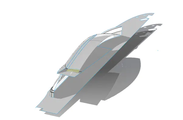
By combining these features, we can model the superstructure and it shown in below figure.
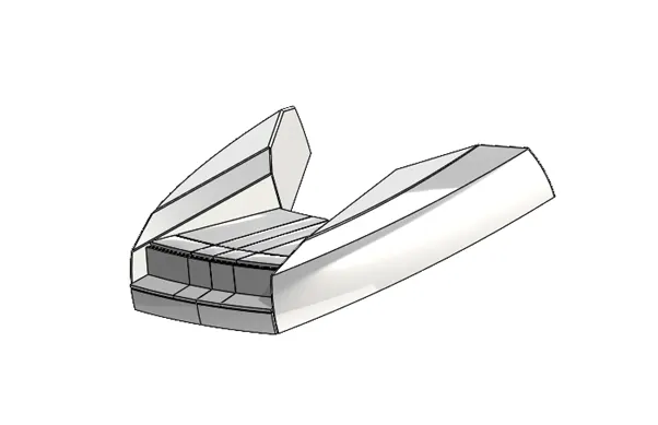
Modelling of the front seat:
All the features used in modelling of the front seat and future models are discussed in detail .
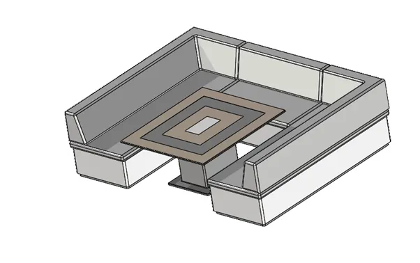
Modelling of the middle seat:
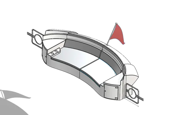
Modelling of the rear seat:
Modelling of Radar mast:
Assembly of the sunseeker yacht:
The assembly of the sunseeker yacht involves the basic mates and aligning the planes.
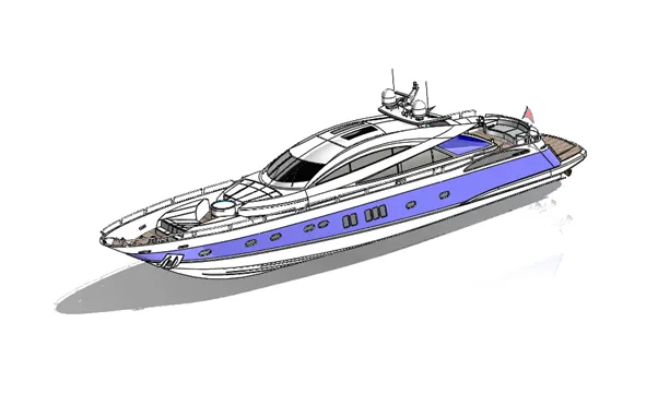
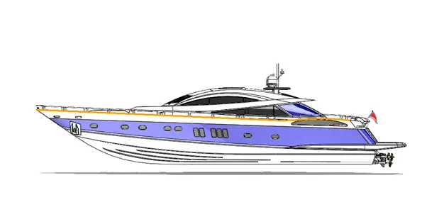
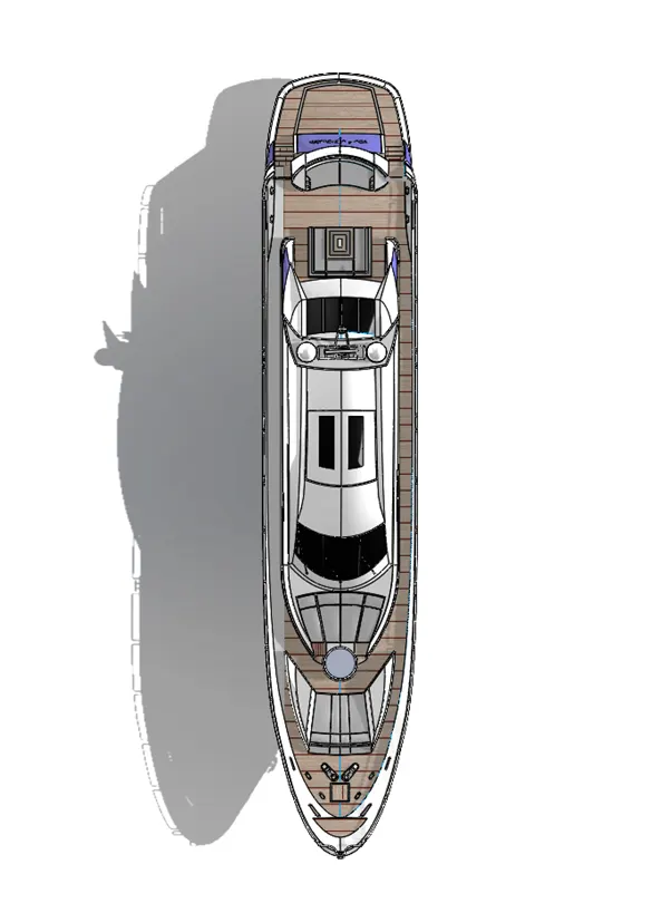
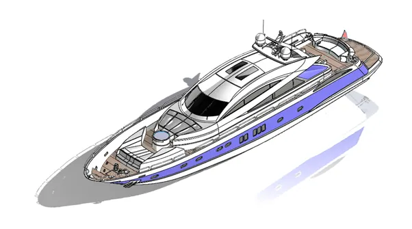
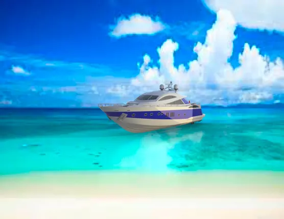
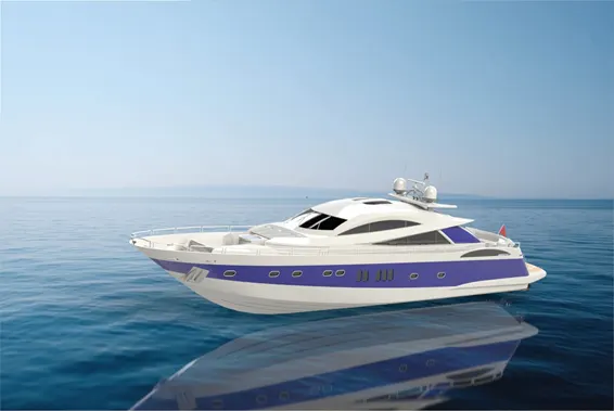
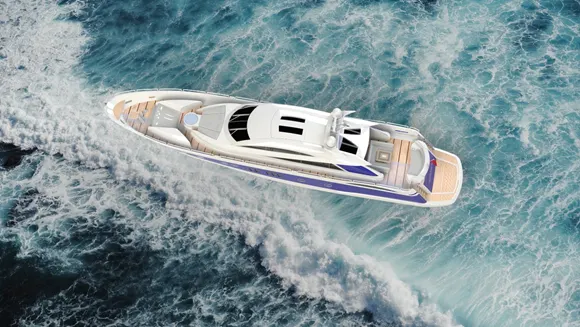
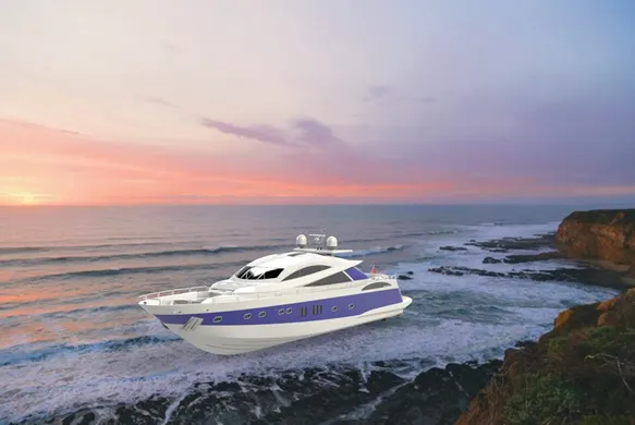
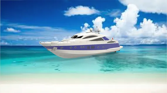
Rendering: The last advance of the Yacht to make it look practical as we have as of now examine the employments of delivering a model here we attempt to make it look however reasonable as it seemed to be conceivable we gotten going with checking the appearance added on every one of the parts then we to make it look more. In addition, giving it a camera see setting the ideal lights and the central distance making the point of the view and saving the camera point which gave a sensible view to the Yacht. Presently we take our gathering record into strong works picture where we begin making the item increasingly more reasonable with adding the foundation changing the and changing the brilliance, shadow thickness and gamma levels as per the various prerequisites of the various foundations changing the shade of the model and genuinely looking at what suits the best with which foundation until we get the ideal and surprising item prepared.
Rendered images:
Conclusion: Finally, modelling of the yacht, assembly and rendering of the model is completed and learned different types of surface modelling features.