Photo Realistic Rendering
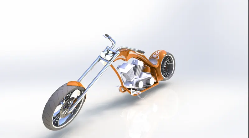
camera view
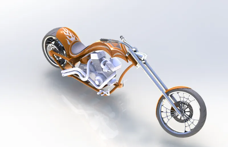
isometric view
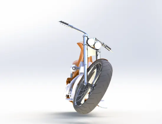
Front view
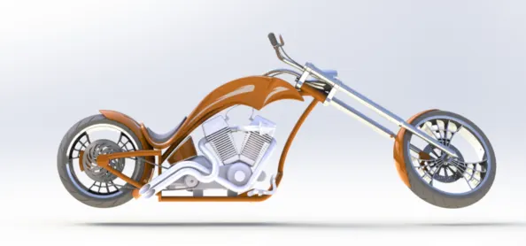
side view
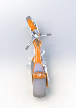
Top view
Report
Modelling of American chopper by learning and applying SolidWorks features.
Chava kristafar
Scope: To learn and understand the modelling features in detail and exploring rendering tools to make the model realistic for developing concepts and final product.
Introduction: In every machine component there are several minor parts, all these minor parts are designed by using 3D modelling software following some standards. Moreover, each part will develop from scratch and pass to different stages to obtain a final product. So, American chopper is also a combination of several parts like transmission belt, gas tank, chassis all these parts are assembled and rendering to get a desired output.
Now, will discuss all the parts we have to model for assembly in detail below:
- Transmission belt
- Kickstand
- Front fender
- Rear fender
- Chain
- Oil tank
- Pedal
- Front wheel
- Rear wheel
- Front fork
- Chassis
- Engine
- Gas tank
We will discuss what are the features used to model these parts details and pictorial representation from designing and assembling is shown in below figure.
Pictorial Representation of Modelling steps:
Features used to design and assembly:
Extrude boss/base: Extrude is feature used to add the material for sketch, If the sketch is closed one it forms a solid body otherwise a surface. In detail, extrude feature is controlled by a property manager which gives access to additional parameters that controlling this feature and allows a desired extrude you want.
Here, the first parameter is ‘from’ means the starting position of extrusion that is from plane/face/surface.
Second parameter is ‘Direction’ means in the which direction this feature have to produce that is blind/vertex (from specific point)/surface (from surface)/offset from surface (certain distance from the selected surface)/up to body (extruded to selected body) midplane (extruded in both direction by mid plane as reference.
Third parameter is ‘Draft’ means draft outward or inward by selecting specific angle.
Fourth parameter is ‘Thin feature’ which creates the Hollow part with specific outline dimension also allows the cap ends. Mainly, it is necessary when we are using open contour sketch.
Extrude cut allows to remove the material from the part using closed sketch and options are similar to extrude boss.
Revolve Boss/base: By using centerline as reference, it adds the or remove material for selected contour. We can apply revolve for multiple intersecting profiles and it does not lie on the centerline. Moreover, the selected profile must be 2D sketch, but the axis of revolution can be a 3D sketch.
Same as extrude boss revolve features can provides the several parameters which controls the revolve by property manager.
Axis of revolution which allows the feature to revolve around the specified axis, it can be a centerline, line, or edge (must be a straight line).
Direction 1 specifying the feature to revolve in one direction by revolve type.
Blind (allows to give an angle)/ up to vertex (until the given vertex or point)/ up to surface (until the selected surface or face)/ offset from surface (end of revolution up to distance from the selected surface)/ mid-plane (controlling both clockwise and anti-clockwise directions from the sketch plane.
Thin feature used to create a thin wall with a given distance from the axis of rotation.
Swept Boss/base: In SolidWorks swept boss is a powerful tool to create the parts in various shapes by specifying path. While there are some conditions to use this feature,
- The profile used for sweep must be closed profile and it should attach to the sweeping path.
- From starting to end the profile should be in constant shape means there should be no variance in the profile shape at all throughout the part.
- If we use guide curves, it must be in coincidence with the profile or the point in a profile sketch.
To use a seep feature, its is recommended to create the path first and then a closed profile, combining by using pierce relation.
Loft boss/ base: Loft boss is similar like swept boss, but the difference is the starting and end profiles of the part are different and it provides more options than sweep to refine the shape.
To create a loft feature we need a minimum of two profiles on planes separated apart. If the profiles are open, then we can create a lofted surface otherwise a closed one. By accessing the property manager, we can create the lofted shape in more desired manner. During the creation of the lofted feature, there are some connecting points between two profiles, by adjusting them we can achieve the synchronization of lofted shape and these connecting points are joined by polylines.
The path that followed from starting profile and the ending profile can controlled by centerline parameter, but the end points of the centerline are coincidence with the profiles. Also, we can insert lofted section between the profiles to enhance the shape and tangency.
Fillet: Fillets are acts like design for safety also for nice and curved edges. We can apply fillets for edges, three consecutive surfaces in 3D drawing and for corners in 2D sketches. Mostly, we can use this feature for internal and external edges. Select the corner or edges you want give fillet and give required fillet radius and click ok to create.
Types of fillets:
- Constant size fillet
- Variable size fillet
- Face fillet
- Full round fillet
Reference geometry: It defines the shape or form of a surface or a solid. Also, it contains
- Plane (To create complex shapes using loft or sweep)
- Axis (used in circular pattern or revolution)
- Co-ordinate geometry (for a part or for an assembly)
- Center of mass (we can represent COM for parts or assembly)
- Boundary box (used to create a box that encloses the created part, and its useful for bill of materials and estimating the stock.
Patterns: Patterns are used to create a Features or bodies in an array-based manner on seed feature. There are different types of patterns based on requirement like linear pattern, curve driven pattern, circular pattern and fill pattern. By propagate visual features, we can replicate the solid works colors and textures and visual properties to all bodies in a pattern. Moreover, this feature allows individual control on pattern bodies to edit or to skip the sequence.
Mirror: Mirror is a very power tool in SolidWorks to save lot of time on parts which are symmetrical to the axis. We can mirror by selecting plane or face or axis in 2-Dsketching. In 3-D modelling features, surfaces and bodies can mirror with reference to plane or surface also can merge bodies together. Lastly, knit surface feature in mirroring allows to combine the mirrored surface when working with surface modelling.
In linear pattern, we can specify the pattern in both X and Y direction and by simply the selecting to skip the instances.
Shell: It creates hollow parts with selected face as opened or closed solid body. This feature is used in manufacturing of parts by investment casting. We can create the hollow part with uniform wall thickness or variable wall thickness.
Projected curves: Projected curve are 3D curves generated by projected planes from 2D sketches. The main concept of projected curve is, every 3D sketch can projected on to the vertical and horizontal plane and is used to create the complex shapes. It can create by sketching a 2D sketch on different planes by projecting them. To visualize better, projected curve is an intersection of two extruded surfaces. Mainly the start and end points of both 2D sketches must be same and there should no intersection in curves.
Mates: Mates are geometric relations to the model, how they move and how they assemble in real-time. In SolidWorks they are different types of mates which allows the user to model the complete model also can perform different analysis.
Some examples are a coincident mate is given to two planar faces. And a cylindrical mate allows to assemble cylindrical parts together. Moreover, same as features, mates can also suppress.
So far, we have discussed the different types of modelling features which are used to design the American chopper, now will discuss the application of these features in detail:
Transmission belt: Design of transmission belt involves the features like extrude and fillets. Its simple flat modeled using a straight slot as a sketch and extruded. And at edges fillets are applied, for realistic view matte rubber is applied as appearance.
Kickstand: Kickstand is main part of the chopper to hold the weight of the body while its stable. So, the shape is like that it should balance the chopper in a perfect position in all environments. For this reason, a loft feature is applied for two ellipses, and both ends of the stand, is guided by a centerline sketch. In addition, a line sketch is used for extrude cut to make flatten at bottom. Also, an extruded cylinder is given to act as a pivot at connection to chopper. Finally, fillets and metal chrome appearance is applied to the part.
Front and Rear fender: Fenders are designed by using a sketch and is revolved with an angle of 130 degrees. The top and bottom cuts are given by sketch and with split feature. The parameter which differs in front and rear fenders is width which depends on size of the wheel. Finally, fillets and painted sienna are applied for appearance.
Oil tank: Oil tank is designed by using combine feature and extracting the common part between two extruded sketches. First a curved sketch is drawn and is extruded vertically, then a wedge like sketch is drawn and extruded horizontally. Now, by using combine feature to removed unwanted area. At last fillets are applied to the edges, appearance of fillet is given as white to match decals. Also, painted sienna is applied as appearance for whole tank.
Modelling of chain: While modelling of chain part, we need to consider the gravity on the chain when it’s in steady state. Also, we must make the chain links as blocks to use in repeatedly. At first, sketching a curved and straight link and make as block, also an outline of the chain is sketched by considering gravity on the chain as shown in below figure.
Now, insert the block and align to the sketch, then extrude the required links and rods. Then with the help of curve driven pattern, creating the number of instances and join. Mainly, at extreme ends if the chain the blocks should insert in such a way that, it must align to the outline of the sketch. Chrome plate is applied as an appearance.
Pedal: The base of the pedal is drawn using lines splines and then extruded the outline and pins from the front plane. Revolve feature is applied to design the footrest and existing sketch for pins are extruded, then dome and fillets are applied. For the pins located outside of the pedal a chamfer feature is applied for finishing and. For grip and to strength the footrest a series of extruded circular plate are drawn and extruded with linear pattern. At last fillets and chrome plate are applied for appearance.
Front and Rear wheel: Designing of the wheel is starts with rim by revolving a rectangle and a profile. Then, a spider web pattern to strengthen the structure using extrude and cuts then by using circular pattern. Next the rotor is designed by extruding the circular disk outward and a pattern of circles with desired angle is created and extruded. To decrease the weight and the eliminate the wastage of material a trapezoidal pattern is sketched and extrude cut is applied. Now, the caliper is sketched on the rotor then extruded and chamfer on both sides to eliminate sharp edges. In addition, by using convert entities and intersection curves the profile of the tire is drawn and revolved around the rim. Finally, using rectangles with certain angles a pattern on the tire is sketched and extrude cut. The same method used to design rear wheel as well.
In addition, a sprocket is design on the rear wheel to mount the chain and transmit the power from engine to the rear wheel.
The appearances of the parts in wheel as follows:
- Tire - matte rubber
- Caliper - painted sienna
- Rotor - carbon steel
- Rim – chromium plate
Front fork: Design of front fork is a tricky one, but it will take less time since it is symmetric to its axis. Its starts with front end bars, a 2D sketch is drawn on the front plane and is revolved complete 360 degrees. Now the connecting structure is drawn and the extruded vertically. Then, creating fillets and the applying linear pattern feature to create similar structure with some distance in same direction. Now, extruded rod from one of the vertical cylindrical rods is created to mount the front wheel, then one of the head lights is created as 2D sketch and revolved 360 degrees and is moved to middle. Next, to place the head light and for illumination, a deep grove like cut is created.
Creating handlebars is bit hard with use of projected curve. To use projected curve, we need two curves that start and end points should be similar. One curve is drawn on horizontal plane, other on the vertical plane. Now, by selecting two curve and create a 3D projected curve. Now, use this curve as path for a cylindrical sweep. The same method is used to create brake and clutch wire, handle grip and brake lever is modeled with the help of revolve feature. Finally, the other part of the model is created by using mirror command and merge together by combine command.
Appearances applied for the front fork are:
- All the cylindrical rods – chrome plate
- Handle grip, brake, and clutch wire – glossy rubber
- Head lights – area lights.
Chassis: Chassis is the main structural member of the chopper to mount engine and all other parts of the chopper, simply called skeleton of automobile. For this mainly use of projected curves and creating different planes and extruding the rectangular members. To start with, a curved cylindrical rod with the aid of projected curves and the sweep feature is generated. At back, a support structure that separates the rear wheel and the engine is sketched in 2D and extruded. To mount the rear wheel, an angular structure is generated by using sweep feature also axle is created. To complete the structure two cylindrical rods with sweep, split and combine features modeled in opposite directions and to place the front fork, a hollow cylindrical rod is sketched. Moreover, a series of rectangular platform to place the engine in fixed position is drawn and extruded also side supporting member are generated. At last, all the sharp corners are molded with fillet feature and painted sienna is applied as a appearance.
Engine casing, fins, and exhaust system: Designing engine and its parts are complex and interesting subject to discuss. It involves use of different features like extrude, sweep, split and projected curves and creating sketches in different planes. To start, a blueprint is imported for reference, a casing is created with circles and lines to cover transmission and internal gearing. Then a projection is extruded from the right of the casing, a hub like shape is created at rear end of engine and by fillet a nice and curved shape is created. Now, on the left side to transmit the power from crank shaft to the flywheel, two cylindrical sections are drawn with tooths on the circumference of the cylinders, also a dome shape is applied at corners of the two cylinders.
Now the creation of fins for the engine, it involves 3 stages, first the solid rectangular shape is modeled, filleted, and attached to bottom member. To create the fin shape, a rectangular extrude cut is applied on top of the vertical member and then with linear pattern feature a series of fins through out the vertical member are generated. On the inside edges of the fins a small L-shaped structure is created for fuel injectors. Then, supporting members at all four corners are sketched and extruded with flat surfaces, to right of the fins a conical shape part for air inlet is created and tooth like profile is on the surface of the conical shape.
Then, exhaust pipes from two extreme sides of the engine are drawn by projected curves and then 3D modeled with sweep feature. At the end the exhaust system a cut like design is appeared by a line with extrude cut feature. Finally, fuel injection pipes are modeled with splines and sweep feature.
Gas tank: In gas tank the features involved all are related to the surface modelling. First a surface is created with sweep of a curve onto spline. Now, with surface trim feature a nice cut shaped is achieved on the right of gas tank, and plane is created exactly on half of the gas tank surface, for creation of the side surface with projected curves and the lofted features. Now, a second plane is created at rear end of the gas tank, to finish the side surface again with help of projected curves and the boundary surfaces. Now a complete side of a gas tank surface is modeled and its time to mirror it and knit the surfaces, by doing this a complete outline profile of a gas tank is created. Next, to create a seat a surface is drawn on the horizontal plane and is projected onto the top surface of the gas tank then is extruded with cap ends. With the help of loft and boundary surface features we can close the bottom side of the gas tank. At last, a surface cut is created by cut sweep to mount gas tank on the chassis and a shell is applied to create a hollow section in tank for fuel. Finally, a grey cotton and painted sienna is applied for seat and the gas tank respectively.
Assembly of an American chopper: Now, open the assembly environment to assemble parts together. To make it easy first import all parts to the assembly module, to start with, chassis is imported and aligned with default planes to make it fix. Then engine is imported, and a coincident mate is applied for planes related to chassis and the engine, again a coincident mate is applied to place engine on the chassis, then a distance mate is applied on the side for exact alignment. Next, import a pedal part and a concentric mate is applied for pedal pin and chassis side frames, then a coincident mate to make pedal together with chassis. Now, import pedal and apply concentric mate for pedal and the chassis left side pin, then to place in position a coincident mate is applied for inner side of pedal and outer side of chassis side pin. To make it real motion a limit angle mate is applied to move the pedal to certain angle.
Now import transmission belt and apply a concentric mate to make it proper alignment to the transmission hub, the with width mate to it align exactly between sections. While the cross section of the toothed profile and the inner circumference of the transmission belt it is hard to exactly place belt on toothed wheel. So, for this an angle mate is applied between the top surface of the engine and transmission belt. With tree coincident mates between the oil tank and engine, oil tank is placed exactly on the engine. For alignment of rear wheel, a concentric mate is applied for axil of rear e\wheel and the chassis, to place in proper position coincident mate for plane of chassis and the rear wheel is applied. Due to the difference in the sprocket and the chain, a width mate is applied with trail and error method. To place the front fork a distance mate is used between the plane and to rotate a front fork same as real scenario a limit angle mate is used. Like rear wheel a series of concentric and coincident mate is used to align front wheel with front fork. To make chopper touch to the ground a series of tangent mate is used in between wheels and the bottom planes.
Rendering: The last advance of the chopper to make it look practical as we have as of now examine the employments of delivering a model here we attempt to make it look however reasonable as it seemed to be conceivable we gotten going with checking the appearance added on every one of the parts then we to make it look more polished we add a few decals on the back bumper and the essence of the oil tank, presently we attempt to make it more sensible by giving it a camera see setting the ideal lights and the central distance making the point of the view and saving the camera point which gave a sensible view to the chopper. Presently we take our gathering record into strong works picture where we begin making the item increasingly more reasonable with adding the foundation changing the and changing the brilliance, shadow thickness and gamma levels as per the various prerequisites of the various foundations changing the shade of the model and genuinely looking at what suits the best with which foundation until we get the ideal and surprising item prepared.
Conclusion: At last, while designing the American chopper different features in solid and surface modelling are learned and applied. Also, assembly of parts and rendering process. When design the parts we need imagine 3d image of part how it looks like and by trail and error methods. To replicate the original product or the concept photo rendering at last is very important to visualize in real environment.
.