Radar Mast & Final Assembly of Yacht
MODELING OF SUNSEEKER PREDATOR 108 YACHT IN SOLIDWORKS
OBJECTIVE
- To model 9 different components using solidworks with various tools, features and methods.
- To assembel the parts using mates and constrains to create the Yacht.
- To add lighting and camera view for rendering.
- The final render with different views and scenes is done with PhotoView 360.
INTRODUCTION
SolidWorks is a solid modeling computer-aided design and computer-aided engineering computer program published by Dassault Systèmes, that runs primarily on Microsoft Windows. We can create both 3D modeling and 2D skeches in this software. Most of the parts created for the chopper are solid bodies. The primary goal of this project is to understand the function and usage of the tools and features for creating the parts. Most importantly we should understand when and where a particular tool or feature is to be used so that the total time spend on sketching and modeling a part would be minimal. The assembly of the yacht will be performed using various mates and constrains and the final render will be performed in PhotoView 360 with the proper lighting, appearance and camera view for a realistic representation of the Yacht.
DESIGN METHODOLOGY
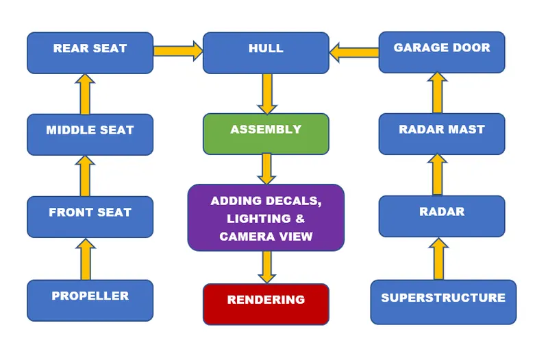
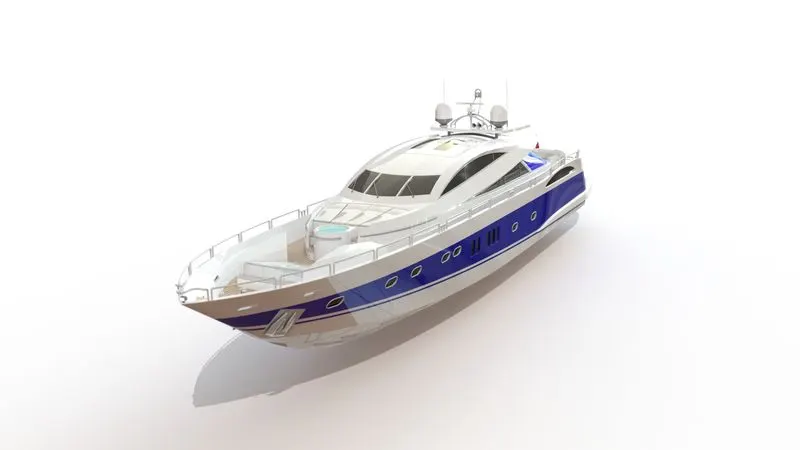
In this design of the Yacht we are using Bottom-Up approach, which is to create the individual parts and assembel them using mates and constrains to create the whole model. The hull will act as the fixed component.
DESCRIPTION OF PARTS WITH THE TOOLS & FEATURES
1. Propeller
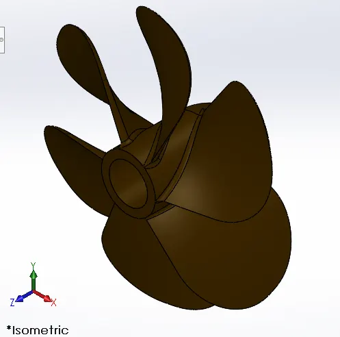
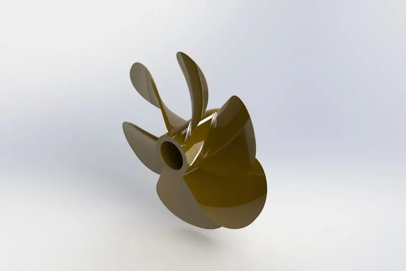
It is the part which enables the forward movement of the yacht. It displaces water in a linear direction with help of uniquely designed curved leaves on a rotating shaft. We are modeling a 6 leafed propeller.
Tools & Features Used
- Revolve
The revolve feature is similar to boss extrude, the only difference is that the extruction is circular. So the parameters include the axis of revolution and the directions are on the basis of angle of rotation.
- Plane
A new plane is offseted with respect to a reference plane for creating a sketch.
- Loft
This tool is used where there are two similar or different sketches on two different planes to be converted in to a solid body with a defined path between the two sketch centers. As we can see in the figure there are two sketch profiles and a centerline parameter. The green dots controls the twist of the loft and will help us to snap to the correct locations.
- Fillet
Fillet feature will create a curved edge to give the part appearance and reduce damage to edges. There is a radius parameter which is 1mm and the selction is done by selecting the inside and outside face. Because the edges are tangential to each other, so the whole edges will get selected which makes the process easy.
- Cut Extrude
This feature performs the function of removing or substracting solid material from a solid body. The parameters include direction of cut which can be changed to a blind direction, through all, upto next, upto surface, upto body, offset from surface, upto vertex, midplane and through all both. We can also change from which plane the extruction should be done even if the sketch is on the other plane.
- Circular Pattern
The circular pattern creates pattern of a body or a feature in circular manner. The parameters can include a circular face or edge, a point or an axis. Here there are 6 instances to create a 6 leafed propeller.
2. Radar
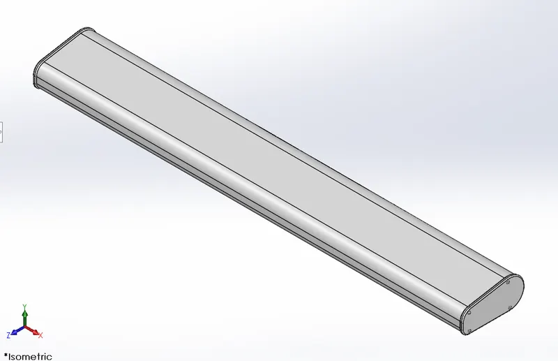
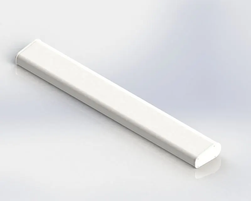
Radar (Radio Detection and Ranging) is a detection system that uses radio waves to determine the distance (range), angle, or velocity of objects.
Tools & Features Used
- Boss Extrude
This a feature that converts a 2D closed sketch to a solid body and the parameters needed are direction and length.
- Sketch Pattern
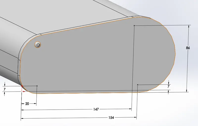
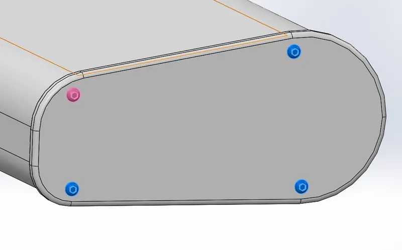
In such a case where we cannot use either linear pattern or cirrcular pattern, then we can use sketch driven patterns. Here for patterning a screw in the other three corners, we create new sketch in the plane we we want to pattern the screw. We make three points which are defined by dimensions. The feature takes this sketch as the location for the features of the screw to be patterened.
- Mirror
The mirror feature is used to create an exact mirror of the selected bodies by taking a reference mirror plane/face. Here the mirror bodies are just the chain plates and the mirror plane is selected as the midplain.
- Split Line
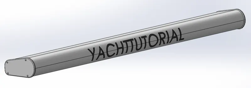
The text sketch is to be projected from a plane to the curved surface of the radar, so the tool split line is used and the parameters are the sketch and the surface to which the sketch is to be projected.
- Fillet
- Cut Extrude
3. Hull
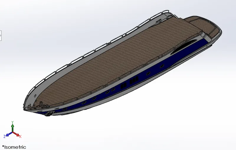
A hull is the watertight body of a ship, boat. The hull may open at the top (such as a dinghy), or it may be fully or partially covered with a deck.
Tools & Features Used
- Sketch Picture
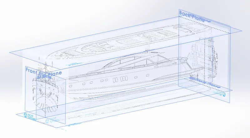
The function of this tool is to help us to create a sketch or a model with the help of a reference image also called as blueprint. We can change its size and give some transparancy so that the skeching will be easy to perform in both sides of the sketch picture plane. Here we use 5 blueprints to aid in modeling the hull, the front view, the back view, the top view, the side view and the bottom view. We also created two new planes, back plane and top plane.
- Project Curve
The project cure feature will create a mutual curve which is reference with the two skeches in two different planes.
- Surface Loft
Like solid body loft, we can create surface with boundaries. Two adjacent profiles are selected and a guide curve acts as a boundary sketch.
- Surface Trim
With a sketch, we can trim away selected sections of a surface.
- Surface Extrude
The surface extrude a shelled varient of a boss extrude. Here we can use weather the top end should be caped or not and weather the bottom face should be present or deleted. We also can knit with in the tool box.
- Surface Knit
Knit surface convets the individual surfaces which have gaps in between them to a single connected surface.
- Surface Fill
With the help of a closed sketch edges, this feature fills with a surface body.
- Shell
Shell feature lets us to convert a solid body to a shell body, which means that there will only be an outer thick wall. The parameter entered is the thickness of the shell wall.
- Sweep
This feature will create a solid body with two parameters, a closed sketch and a curve. So a projected curve can be used to create a 3D sweeping extrude.
- Dome
The dome feature will convert a flat face into a dome with a length parameter.
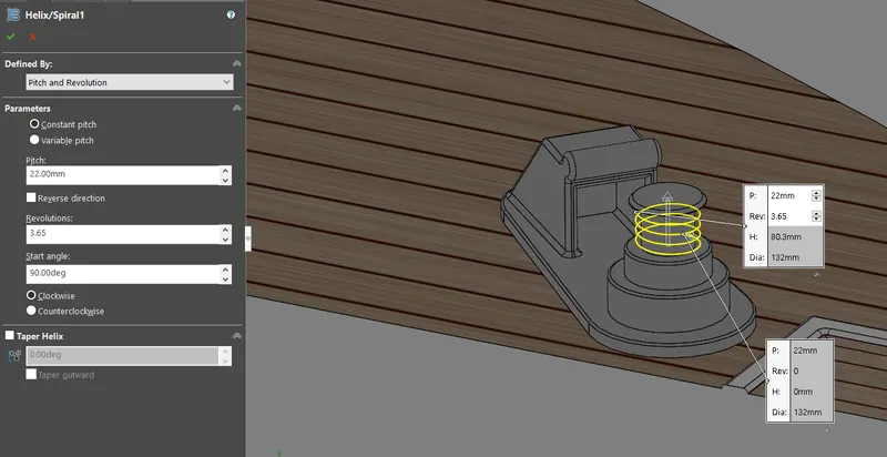
- Helix/Spiral
It creates helix like 3D sketch with parameters include, constant or variable pitch, pitch, revolution, start angle and clockwise or counterclockwise.
- Linear Pattern
Linear pattern is a usefull feature which reduce time of modeling a particular feature which repeats itself in a linear direction. Here a solid like structure is linearly patterned and the parameters needed for this process is the number of instance and the spacing in between two instances. Also an edge is selected to identify the direction. We have selected the features like fillet and boss extrude to pattern, in the case of patterning a whole body we can check the body tab and add the solid body to pattern.
- Delete Face
This feature can be used to delete unwanted faces in the model.
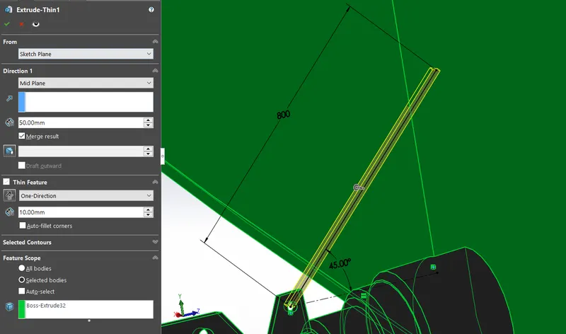
- Extrude Thin
With the help of a line sketch we can create a solid body. In the boss extrude there is a thin feature option, in which we can add the thickness value along with the extrusion value.
- 3D Sketch
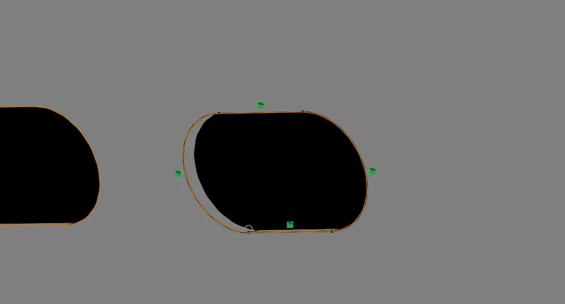
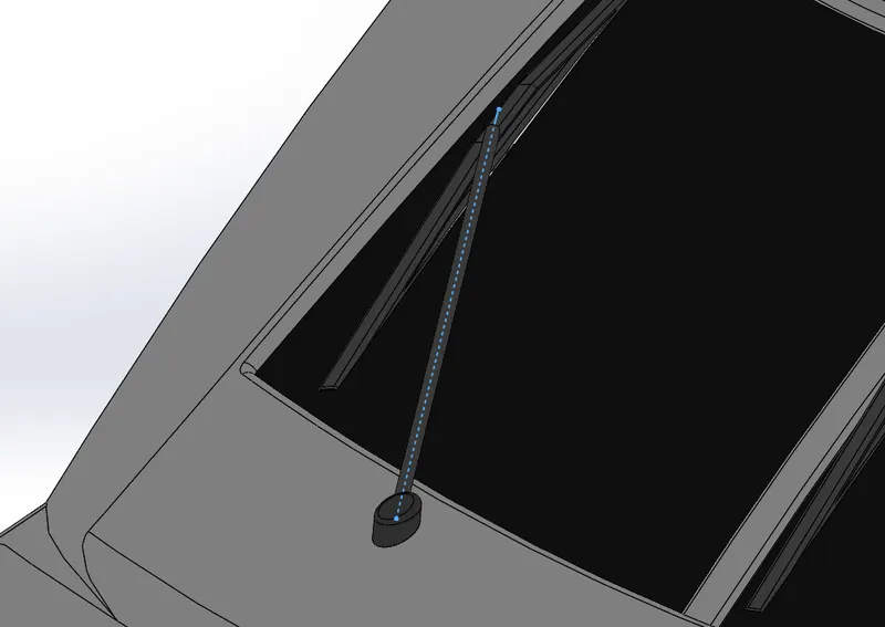
A 3D sketch is independent of planes. We can sketch any shapes or curves in the 3D space. We define the position of the sketch with help of constraining the points. We can convert a 3D edge using this feature.
- Split
Split is a feature used to cut and remove a solid body from its parent solid body. This can be done by just drawing a line. In the split feature box we need to select the body to be remove and click on "consume cut bodies". The cut part can also be saved externally. Here we save the split body to be used as the reference model for the garage door.
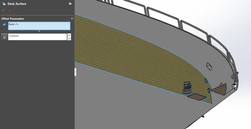
- Offset Surface
We use this in this built to create a copy of the hull top surface by giving a offset value of 0mm. This copy of the surface is used for applying decals on the floor.
- Chamfer
The chamfer feature creates a angular cut at the edge of a solid body. Here the solid body is a cylinder and the type of chamfer is a "distance distance" type with two different distance parameters which will create a sharp point.
- Plane
- Boss Extrude
- Cut Extrude
- Fillet
- Revolve
- Split Line
- Mirror
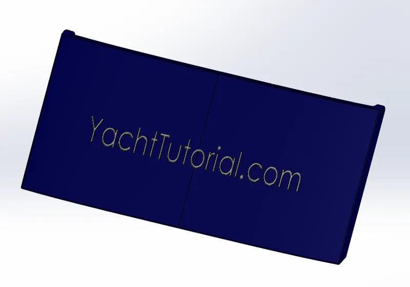
4. Garage Door
It is flat body which protects a garage from external elements. Here the garage is used to park a car and the door protects the car from the sea water and corrosion.
Tools & Features Used
- Cut Extrude
- Shell
- Fillet
- Mirror
- Plane
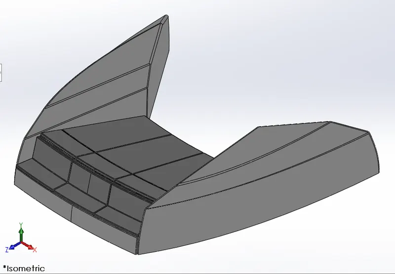
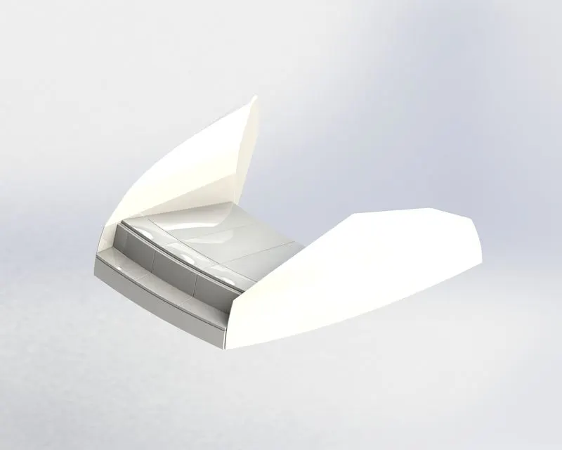
5. Front Seat
It is placed in front of the superstructure for the passenger to sit in and look at the view.
Tools & Features Used
- Plane
- Surface Sweep
- Surface Extrude
- Surface Trim
- Surface Fill
- Surface Loft
- Surface Knit
- Chamfer
- Revove
- Cut Extrude
- Fillet
- Mirror
- Dome
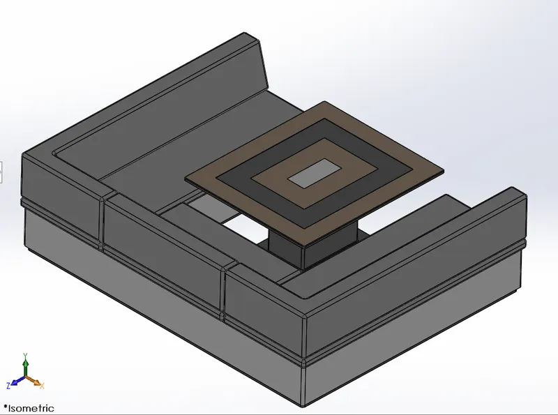
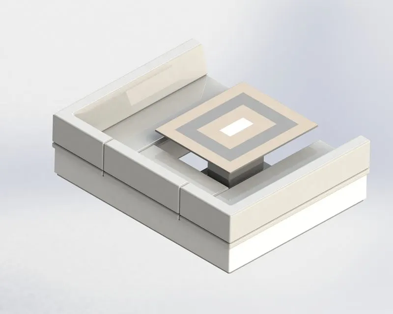
6. Middle Seat
It is an seat which has compartments and table for the middle of the yacht.
Tools & Features Used
- Boss Extrude
- Plane
- Chamfer
- Fillet
- Mirror
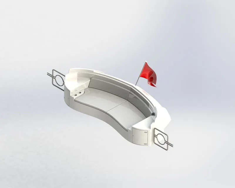
7. Rear Seat
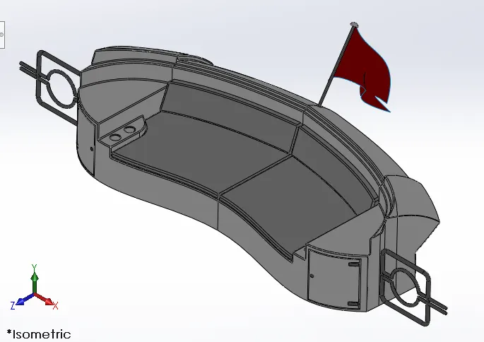
It is seat which is at the rear of the yacht with a flag fixed on the back and a gate at either side.
Tools & Features Used
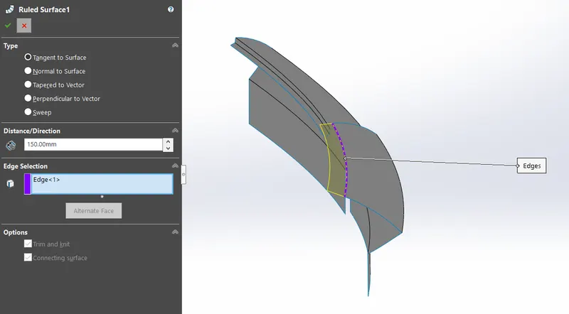
- Ruled Surface
The Ruled Surface command creates surfaces that extend out in a specified direction from selected edges. There extended surface will be equally divided with points which are on the selected edge.
- Surface Sweep
- Surface Offset
- Surface Trim
- Surface Knit
- Plane
- Surface Extend
- Surface Extrude
- Surface Loft
- Boss Extrude
- Cut Extrude
- Chamfer
- Fillet
- Sweep
- Mirror
- Revolve
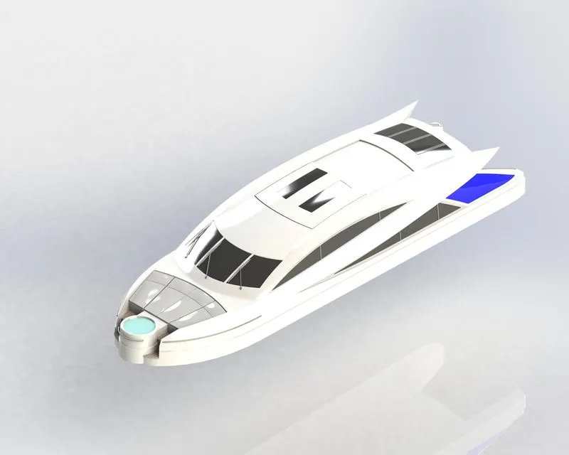
8. Superstructure
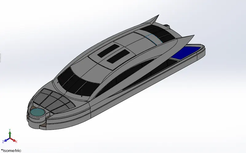
This the structure in which the passengers and the driver of the yacht is accomodated. The controls of the yacht will also be in it. There is also a integrated jacuzzi.
Tools & Features Used
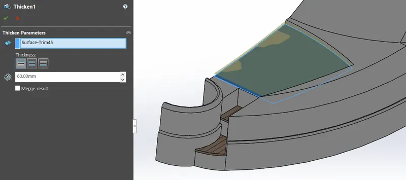
- Thicken
It gives thickness to the selected surface.
- Surface Extrude
- Plane
- Surface Sweep
- Surface Knit
- Fillet
- Ruled Surface
- Surface Trim
- Curve
- Surface Loft
- Surface Fill
- 3D Sketch
- Surface Extend
- Boss Extrude
- Cut Extrude
- Delete Face
- Surface Offset
- Dome
- Sweep
- Extrude Thin
- Split Line
- Mirror
- Chamfer
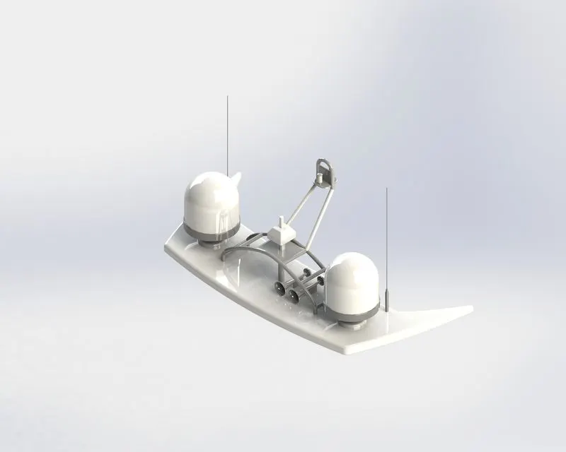
9. Radar Mast
It is the structure which holds the radar, antenas and other functional equipment like lights & horn. They are electronic navigation instruments that use a rotating antenna to sweep a narrow beam of microwaves around the water surface surrounding the ship to the horizon, detecting targets by microwaves reflected from them, generating a picture of the ship's surroundings on a display screen.
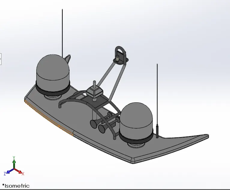
Tools & Features Used
- Plane
- Boss Extrude
- Fillet
- Revolve
- Sweep
- Mirror
- Curve
- Chamfer
- Dome
- Shell
- Combine
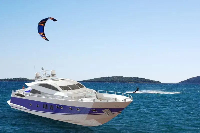
ASSEMBLY OF THE YACHT
The hull is the part which is fixed in place and helps as a reference for mating other components.
Mates Used
- Coincident: This mates makes the selected entities on the same plane.
- Concentric: The selected circular edge or a vertex will have a common center after applying this mate.
Assembly Model Rendered Views
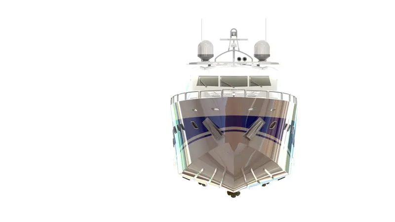
- Front View
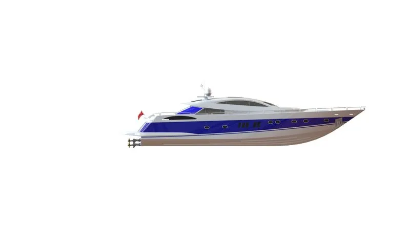
- Side View (Left Side)
- Isometric View
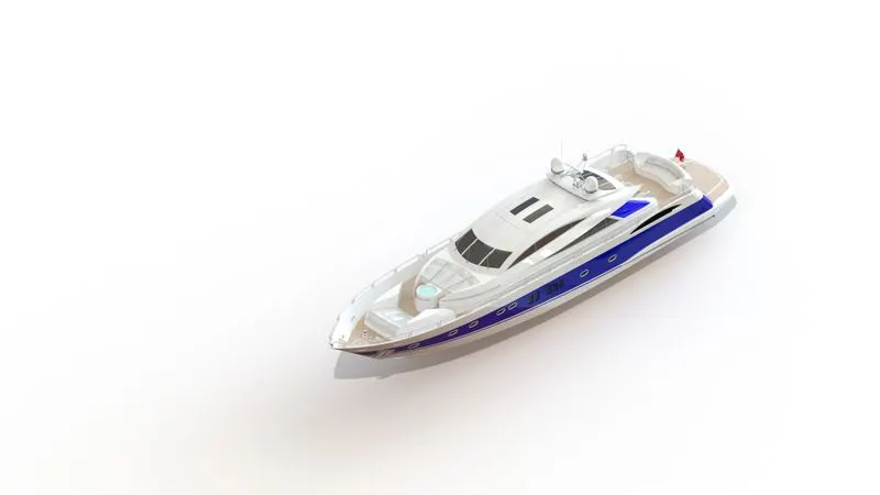
- Camera View
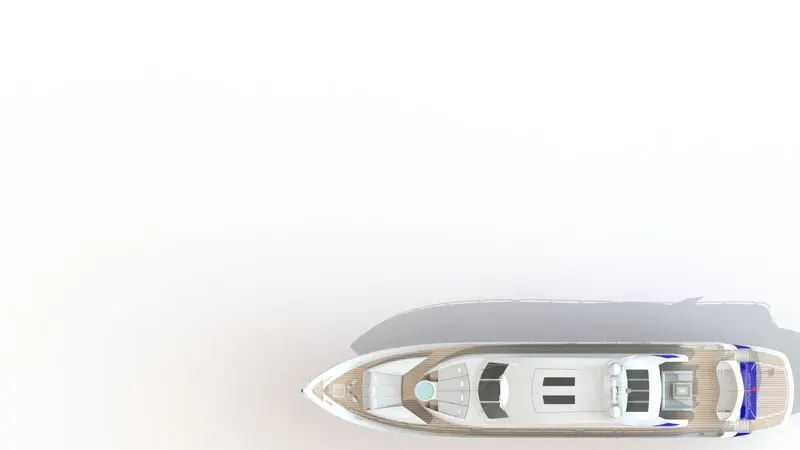
- Top View
Rendered Parts
- Propeller
- Radar
- Hull
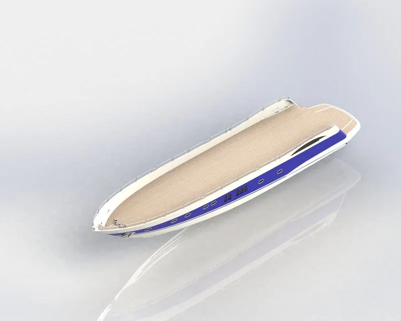
- Garage
- Front Seat
- Middle Seat
- Rear Seat
- Superstructure
- Radar Mast
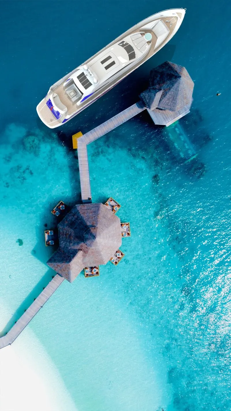
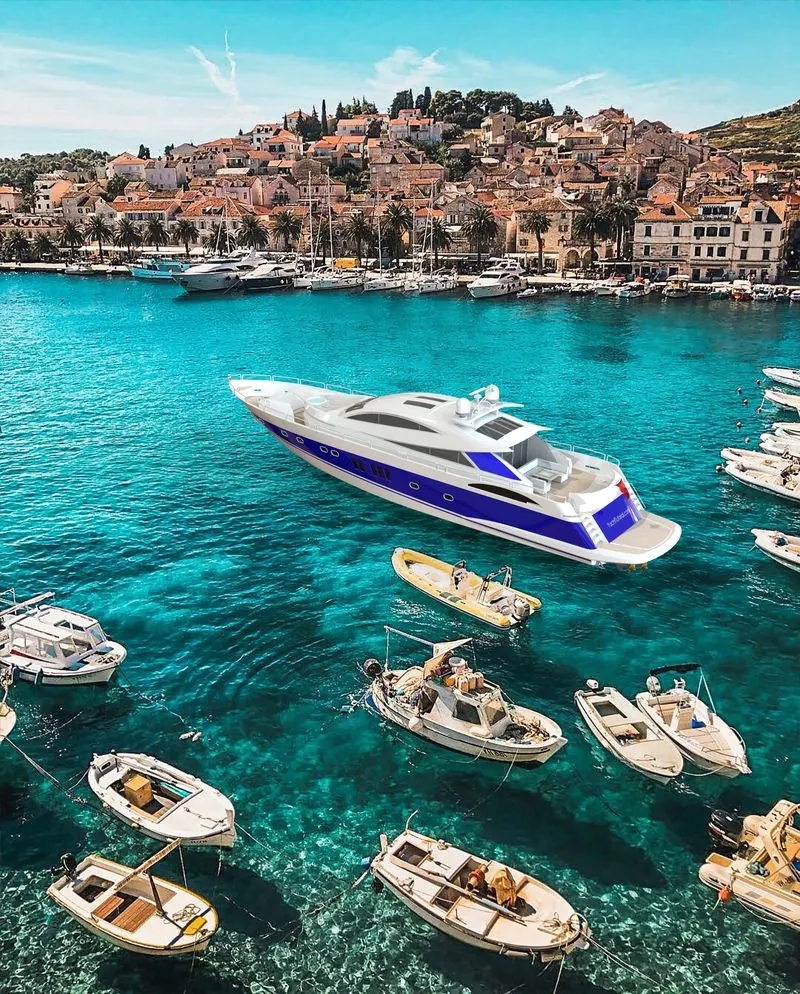
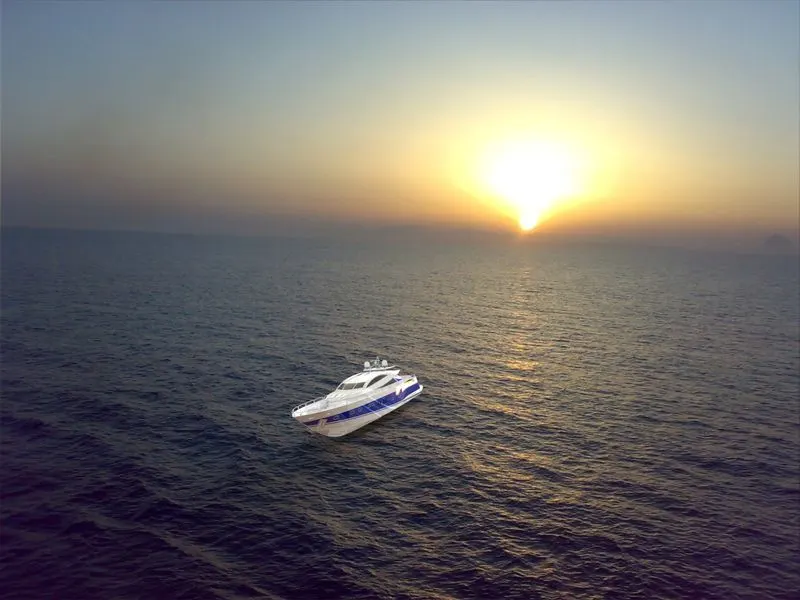
Rendered Images of Assembly with Scenes
CONCLUSION
After finishing this project, i understood the various tools and features and when and where to use them for sketching and modeling a component efficiently. Learned some tips and tricks. Performed adding decals, lighting and camera view to the Yacht and understood tools on how to make the model more realistic for a final render after adding scenes. Acquired more knowledge on surface modeling.