Photo Realistic Rendering
MODELLING OF AMERICAN CHOPPER IN SOLIDWORKS
OBJECTIVE
- To model 13 different components using solidworks with various tools, features and methods.
- To assembel the parts using mates and constrains to create the American Chopper.
- To add decals, lighting and camera view for rendering.
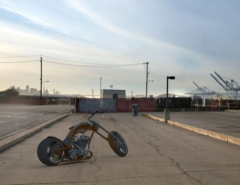
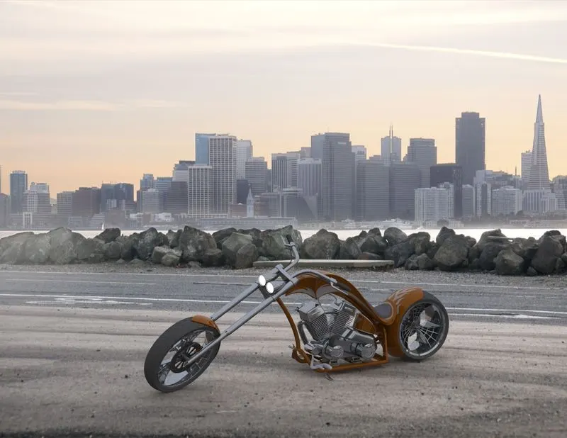
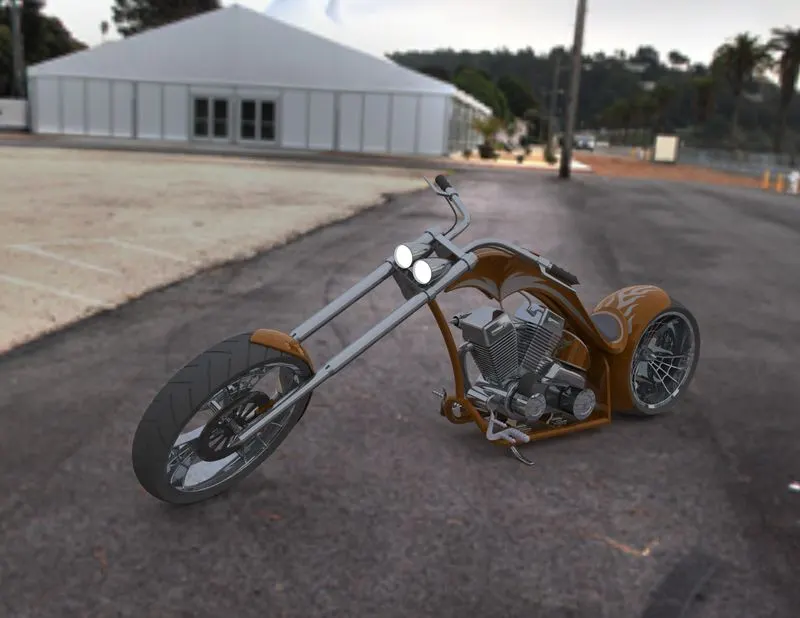
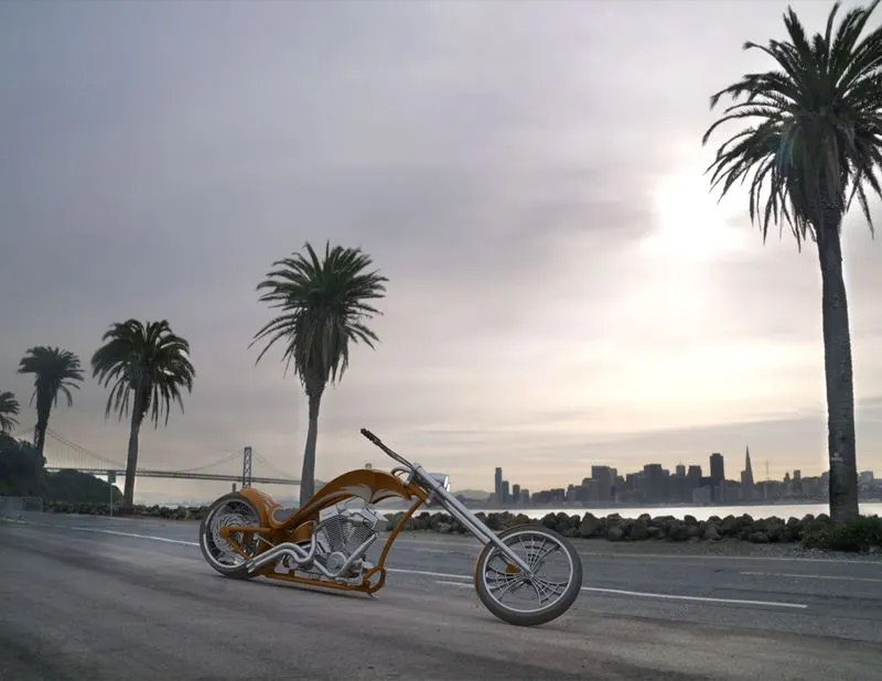
- The final render with different views and scenes is done with PhotoView 360.
INTRODUCTION
SolidWorks is a solid modeling computer-aided design and computer-aided engineering computer program published by Dassault Systèmes, that runs primarily on Microsoft Windows. We can create both 3D modeling and 2D skeches in this software. Most of the parts created for the chopper are solid bodies. The primary goal of this project is to understand the function and usage of the tools and features for creating the parts. Most importantly we should understand when and where a particular tool or feature is to be used so that the total time spend on sketching and modeling a part would be minimal. The assembly of the chopper will be performed using various mates and constrains and the final render will be performed in PhotoView 360 with the proper lighting, appearance and camera view for a realistic representation of the American chopper.
DESIGN METHODOLOGY
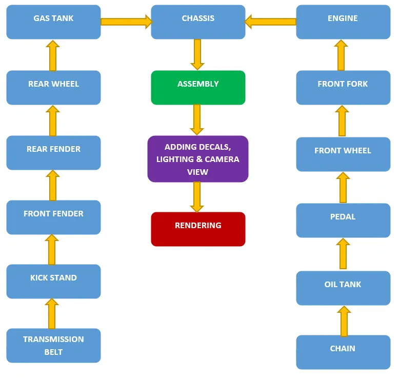
In this design of the American Chopper we are using Bottom-Up approach, which is to create the individual parts and assembel them using mates and constrains to create the whole model. The chassis will act as the fixed component
DESCRIPTION OF PARTS WITH THE TOOLS & FEATURES
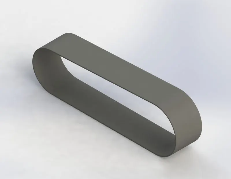
1. Transmission Belt
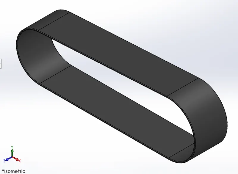
The function of this part is to transfer the roatatinonal motion from one shaft to another. The material given is matte rubber.
Tools & Features Used
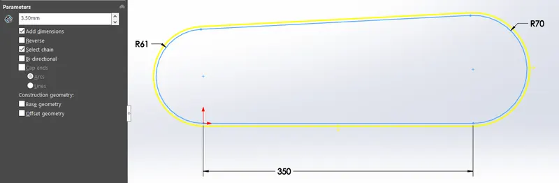
- Offset
This tool helps us to displace a line or curve linearly in its perpendicular axis with defined length and direction. Here we can select the lines individually or by turning on "select chain" and clicking any one line, then the lines and curves which has tangential relation will also get selected.
- Extrude
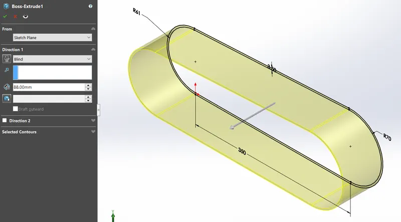
This a feature that converts a 2D closed sketch to a solid body and the parameters needed are direction and length. Here the direction is selected as blind towards us with 88mm.
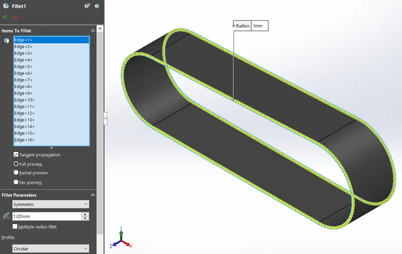
- Fillet
Fillet feature will create a curved edge to give the part appearance and reduce damage to edges. There is a radius parameter which is 1mm and the selction is done by selecting the inside and outside face. Because the edges are tangential to each other, so the whole edges will get selected which makes the process easy.
2. Kickstand
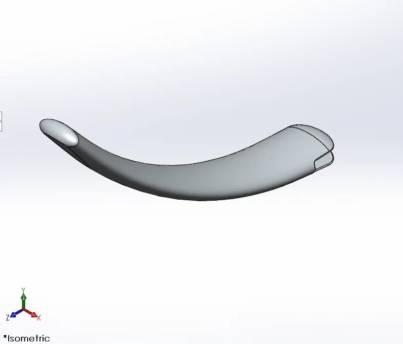
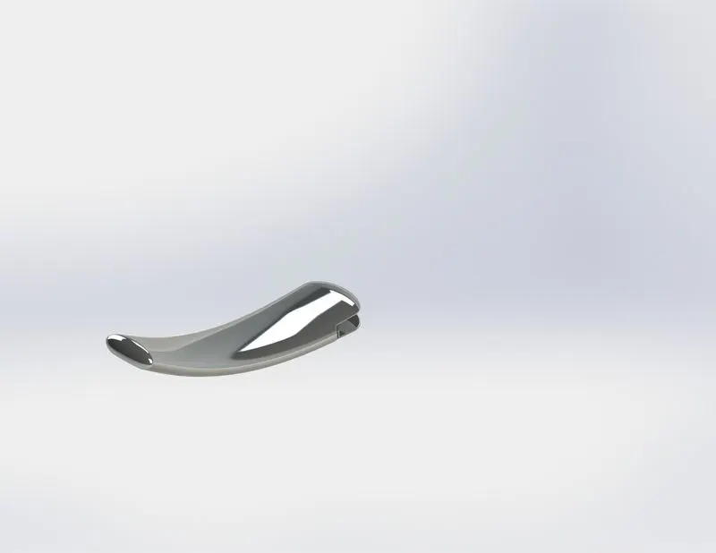
This parts function is to support the bike in its stationary position. It is concentically mated with a bore on the chassis. A flat surface is given at the bottom. The material given Chromium plate.
Tools & Features Used
- Spline
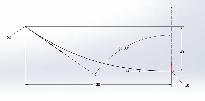
A spline is a free hand drawn curve. We can chage its radius and if we enable tangent driving by clicking on the spline we can see a handle at each spline vertex. The handle has end arrow which gives the spline at that end a weight which is a parameter in millimeters and there is a up and down arrow at the midpoint of the handle which controls the angular rotation at that end of the spline. Here in this two point spline the spline will be straignt line but by clicking on the spline we made the bottom spline handle horizontal and the upper spline handle an angle of 55 degrees with respect to the vertical construction line.
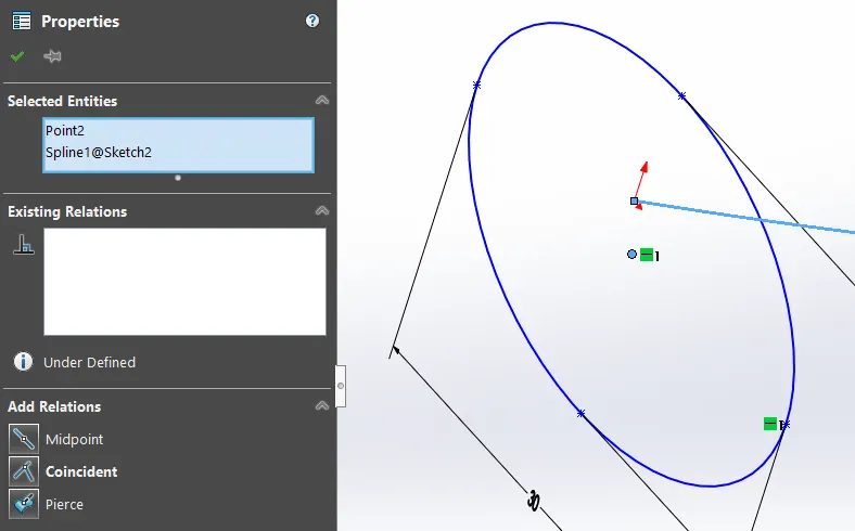
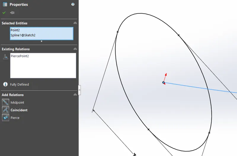
- Make Pierce
This is a constrain that helps us to make the spline on a perpendicular plane to the plane of the elipse to be in contact with the center of the elipse.
- Loft
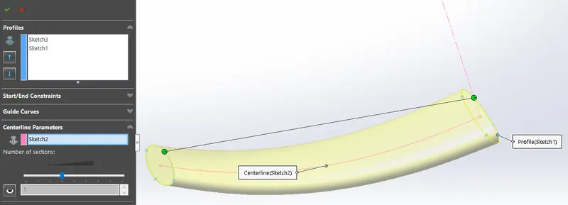
This tool is used where there are two similar or different sketches on two different planes to be converted in to a solid body with a defined path between the two sketch centers. As we can see in the figure there are two sketch profiles and a centerline parameter. The green dots controls the twist of the loft and will help us to snap to the correct locations.
- Dome
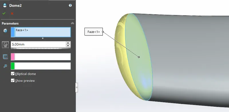
Th dome feature will convert a flat face into a dome with a length parameter.
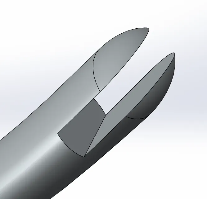
- Cut Extrude
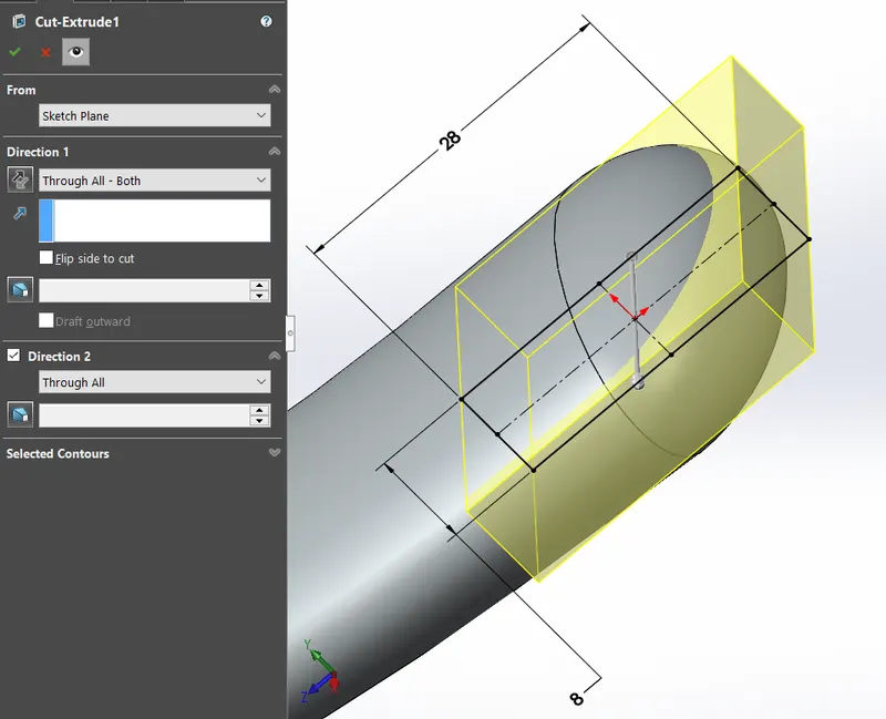
This feature performs the function of removing or substracting solid material from a solid body. The parameters include direction of cut which can be changed to a blind direction, through all, upto next, upto surface, upto body, offset from surface, upto vertex, midplane and through all both. We can also change from which plane the extruction should be done even if the sketch is on the other plane.
- Split
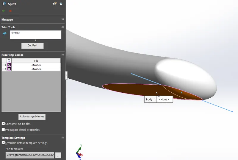
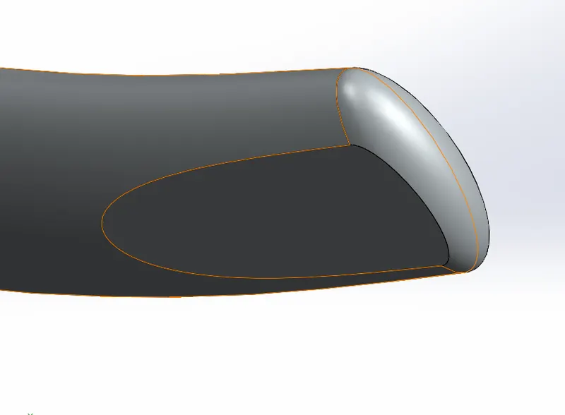
Split is a feature used to cut and remove a solid body from its parent solid body. This can be done by just drawing a line. In the split feature box we need to select the body to be remove and click on "consume cut bodies". The cut part can also be saved externally.
- Boss Extrude
- Fillet
3. Front Fender
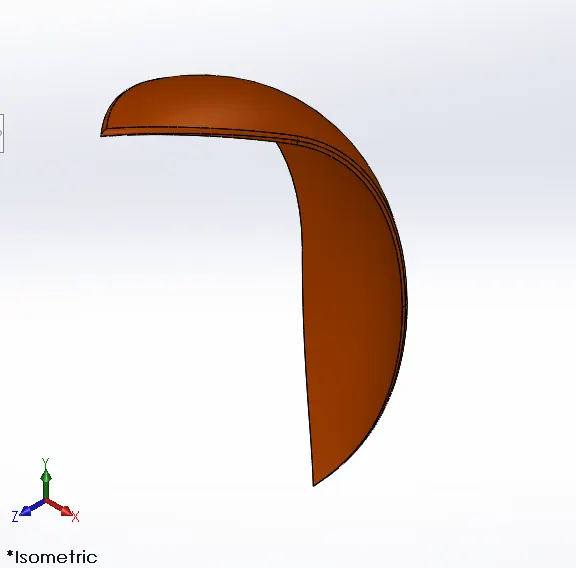
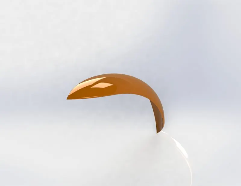
The front fender protects the rider from mud and debris. The appearance given is siena colour.
Tools & Features Used
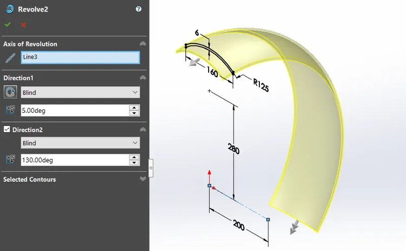
- Revolve
The revolve feature is similar to boss extrude, the only difference is that the extruction is circular. So the parameters include the axis of revolution and the directions are on the basis of angle of rotation.
- Split
- Fillet
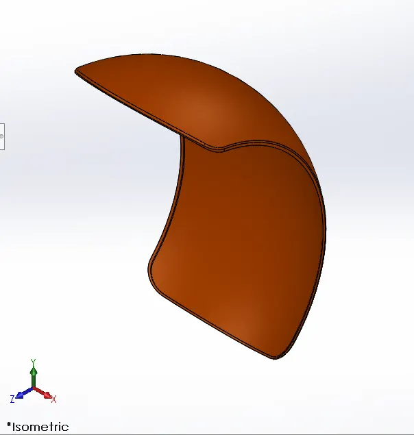
4. Rear Fender
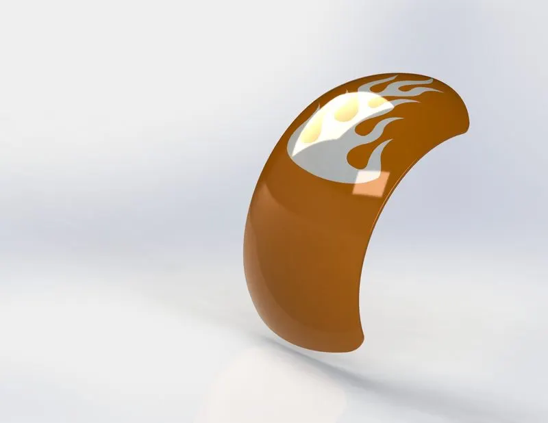
The rear fender performs the function of protecting the rider and engine from mud debris. The appearance is siena colour.
Tools & Features Used
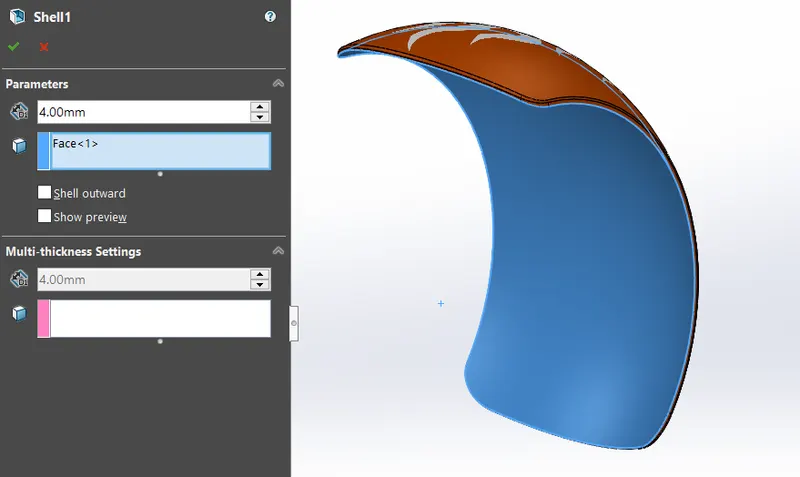
- Shell
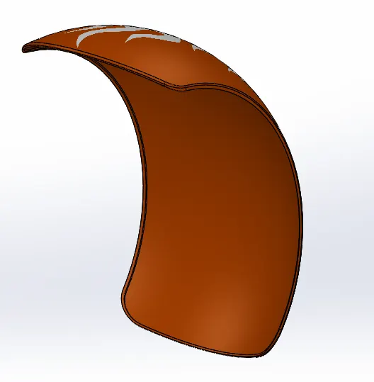
Shell feature lets us to convert a solid body to a shell body, which means that there will only be an outer thick wall. The parameter entered is the thickness of the shell wall. In this fender the shell is created on the inner face to create a ridge around the outer edge of the fender.
- Revolve
- Split
- Fillet
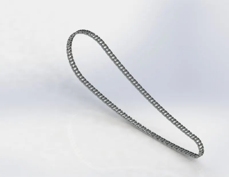
5. Chain
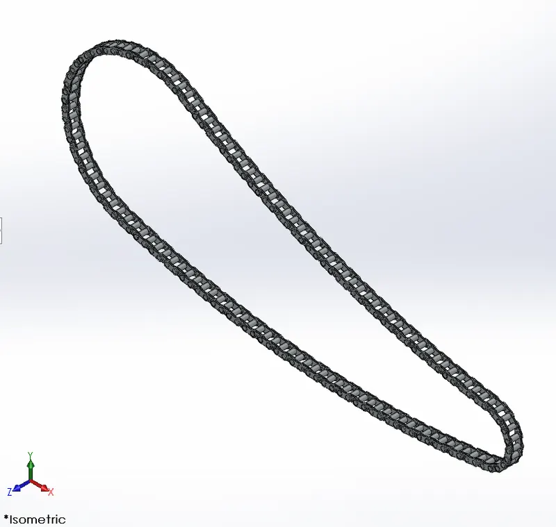
A chain is an assembly of two or more parts which enable the transmission of rotational motion from one shaft to another. Unlike a belt there are repetated links which make the component flexible in a particular plain. There are slots which enable the teeth of the sprocket to be in mesh. The material given to the chain is Chromium plate.
Tools & Features Used
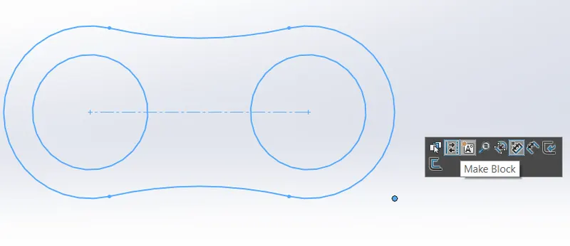
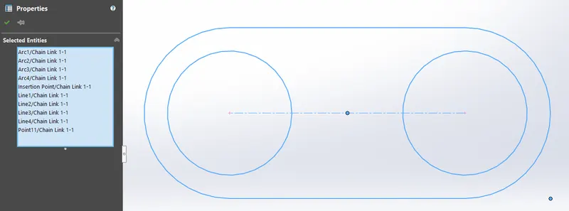
- Make Blocks
Make blocks is a sketch feature which enable us to create a unrelated sketch on the same plane as the primary sketch to be saved externally with the file format SLDBLK to be used in the future sketches. This enabled me to create the two links as shown in the figure to be used in the curve driven patterning for making the chain links.
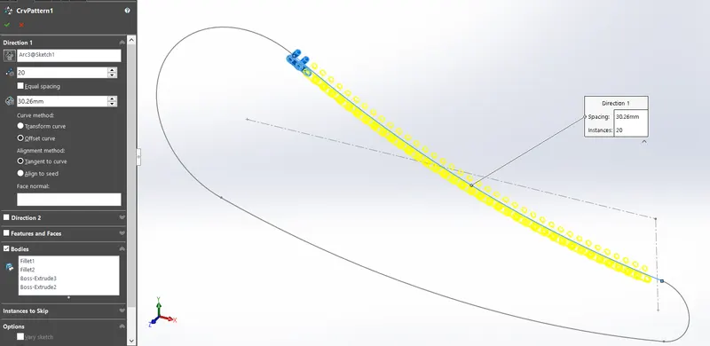
- Curve Driven Patterning
There are linear patterning which patterns a sketch in a linear direction and there is circular patterning which patterns a sketch in curcular manner with the center reference. Since in the modeling of chain, we have predefined closed sketch which act as a guide curve for the links to follow. So a curve driven pattern is a powerful feature which enables just that.
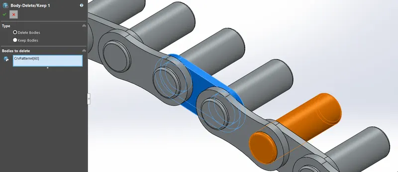
- Delete/Keep Body
This feature is used to delete the unwanted body which is the internal link because the circular bore is not concentic with the circular extrude. This odd link was patterned so deleting that single element would be possible through this feature.
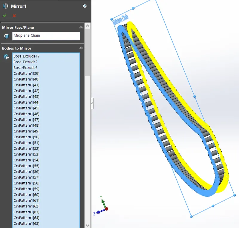
- Mirror
The mirror feature is used to create an exact mirror of the selected bodies by taking a reference mirror plane/face. Here the mirror bodies are just the chain plates and the mirror plane is selected as the midplain. To make the selection of the chain plates easy, in the solid body dropdown the chain plates are grouped together in a single file.
- Boss Extrude
- Fillet
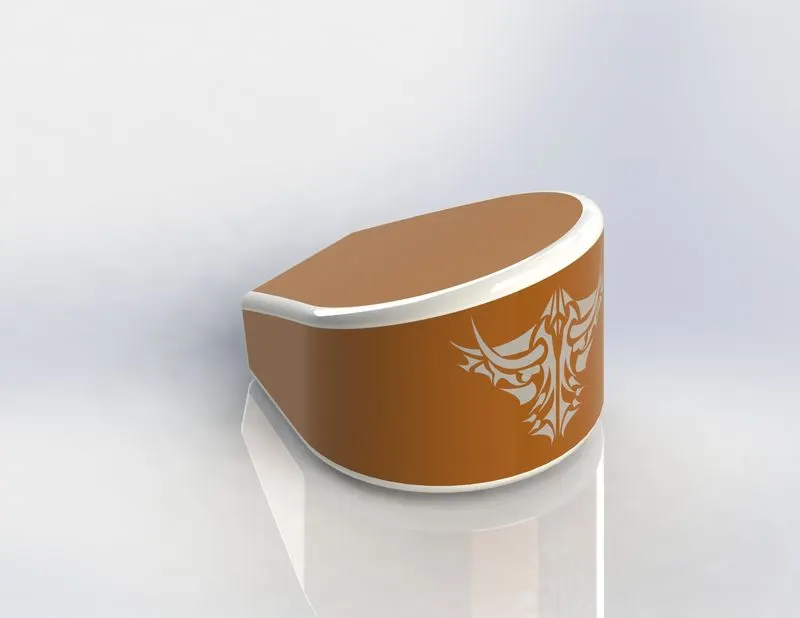
6. Oil Tank
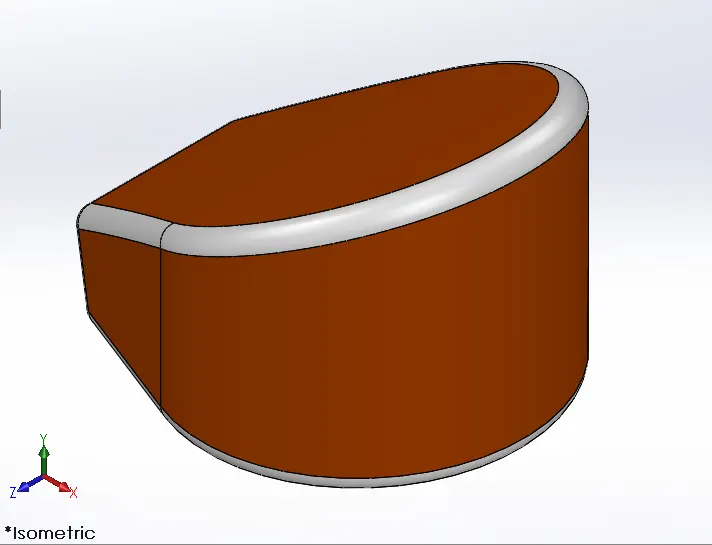
It is a container that stores oil for it to be used in the engine. The colour for the tank is siena and white.
Tools & Features Used
- Combine
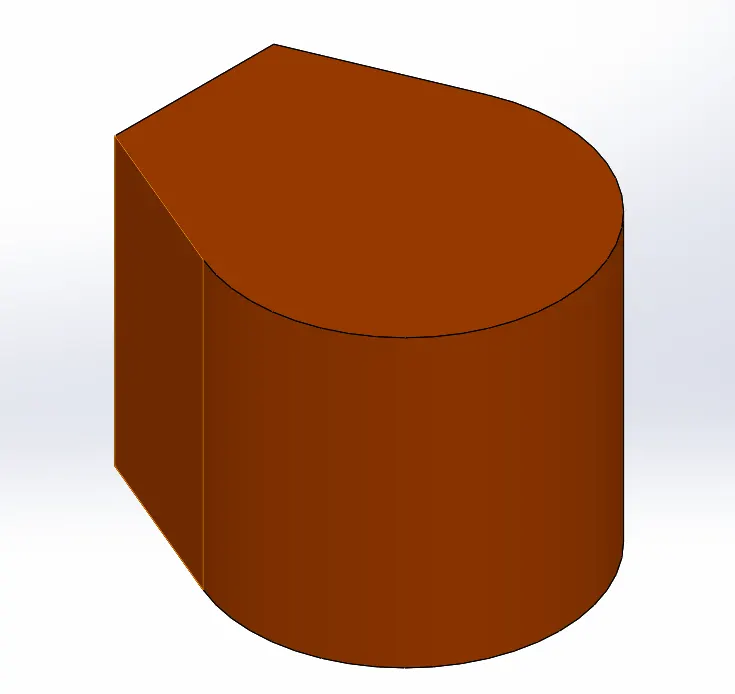
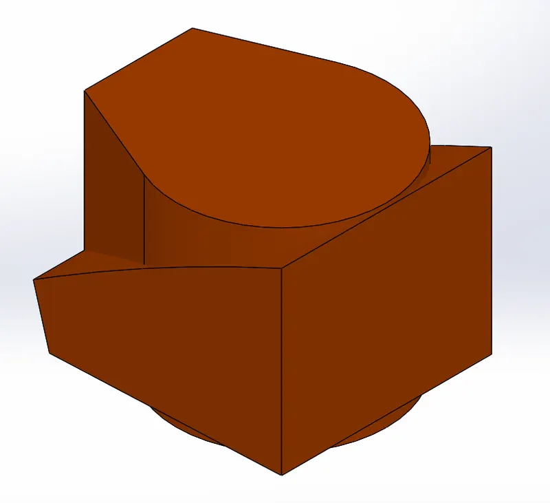
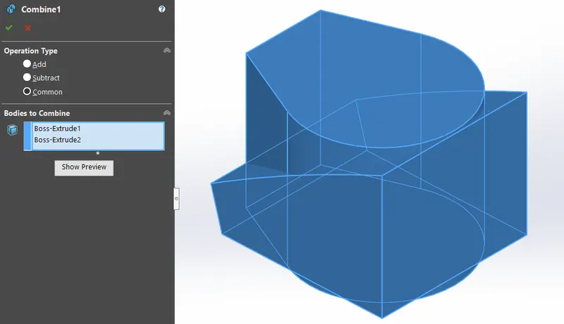
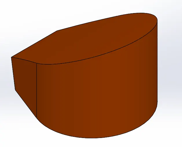
In the model of the oil tank, there are several methods to create it. By using combine feature it is a three step procedure. First a skech is boss extruded from the top plain and a second sketch is also extruded in the right plain. Both the bosses are midplane extrudes. Then use the combine feature and select the two boss extrudes and check the "common" in operation type. The end result will the visual of the common solid that intresects with both the boss extrudes.
- Boss Extrude
- Fillet
- Shell
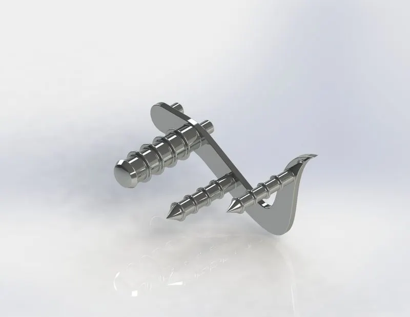
7. Pedal
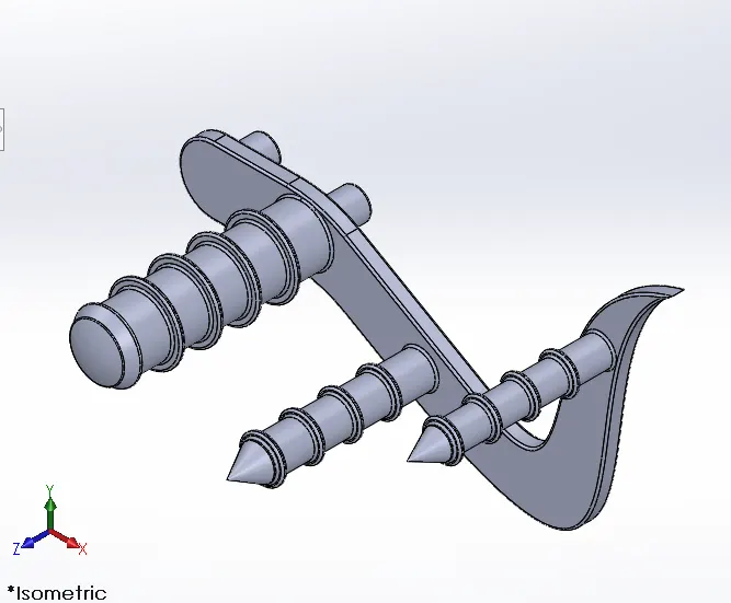
The fuction of the pedal is to act as a foot rest and to change gears or to apply brake to the rear wheel. The material used is Chromium plate.
Tools & Features Used
- Chamfer
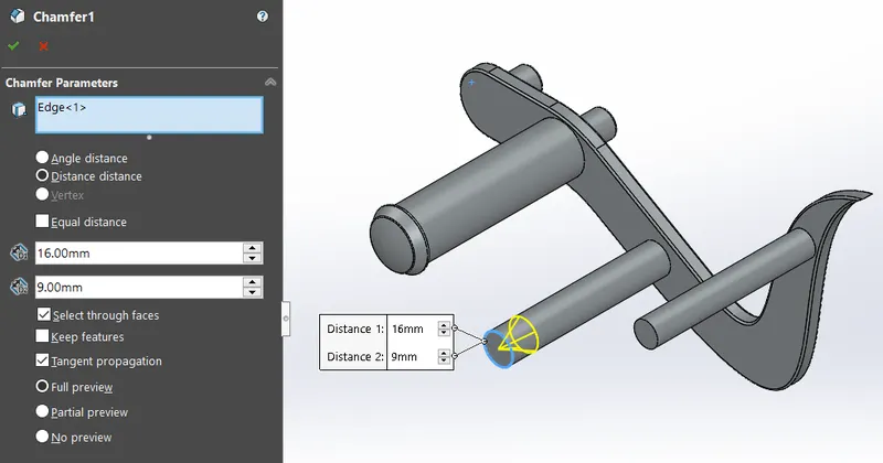
The chamfer feature creates a angular cut at the edge of a solid body. Here the solid body is a cylinder and the type of chamfer is a "distance distance" type with two different distance parameters which will create a sharp point.
- Lineat Pattern
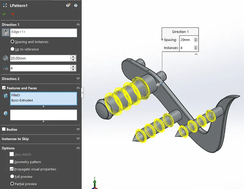
Linear pattern is a usefull feature which reduce time of modeling a particular feature which repeats itself in a linear direction. Here a ring like structure is linearly patterned and the parameters needed for this process is the number of instance and the spacing in between two instances. Also an edge is selected to identify the direction. We have selected the features, fillet and boss extrude to pattern, in the case of patterning a whole body we can check the body tab and add the solid body to pattern.
- Boss Extude
- Fillet
- Revolve
- Dome
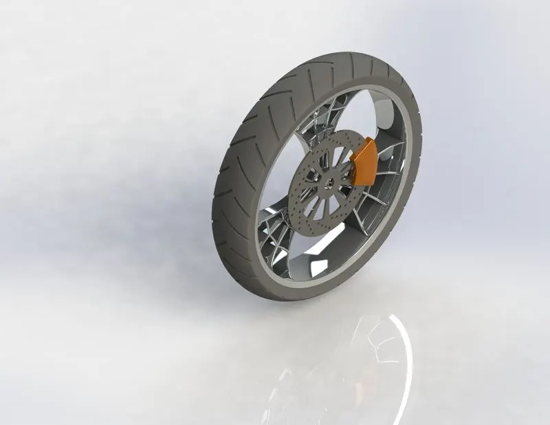
8. Front Wheel
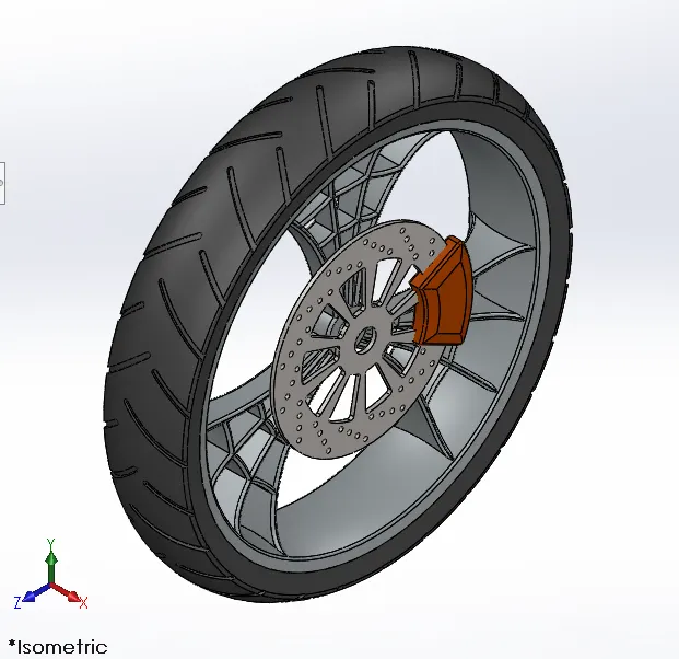
The function of the front wheel is to enable the bike to be moble, to turn and to support the front section of the bike. It houses a disk for braking. The appearance given to the tyre is matt rubber, Chromium plate for the wheel and disk and siena for the brake caliper.
Tools & Features Used
- Cut Revolve
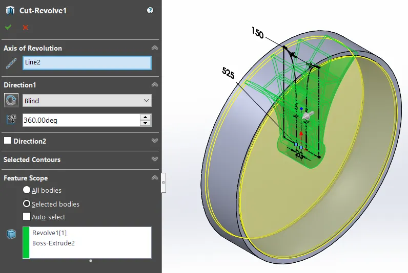
This feature is similar to the cut extrude tool. Instead of linear extruction here the extruction is curcular with respect to the center point or axis of rotation. Here the extruction is 360 degrees.
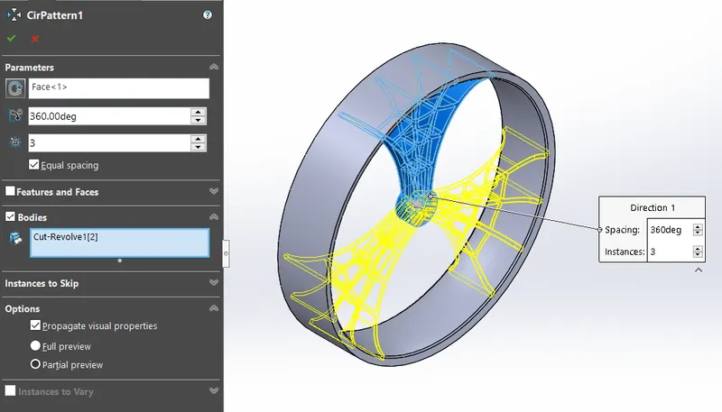
- Circular Pattern
The circular pattern creates pattern of a body or a feature in circular manner. The parameters can include a circular face or edge, a point or an axis. Here there are 3 instances to create a 3 spoked wheel.
- Revolve
- Boss Extrude
- Extrude Cut
- Combine
- Fillet
- Chamfer
9. Rear Wheel
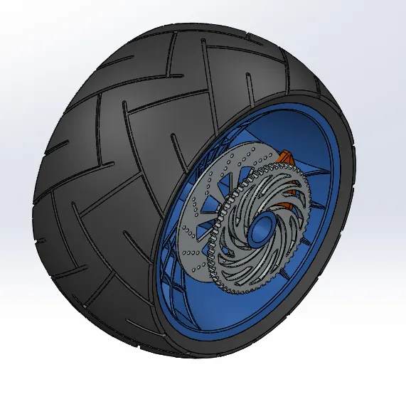
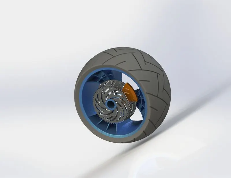
The function of the rear wheel is to transfer the engines work into linear motion via the rotation of the rear wheel. It connects the chain from the engine to the sprocket attached to the wheel. It also have disk for braking. The appearance include matt rubber for tyre, Chromium plate for sproket and disk, blue anodized Aluminium for the wheel and siena for the brake caliper.
Tools & Features Used
- Revolve
- Boss Extrude
- Cut Extrude
- Circular Pattern
- Combine
- Cut Revolve
- Fillet
- Chamfer
10. Front Fork
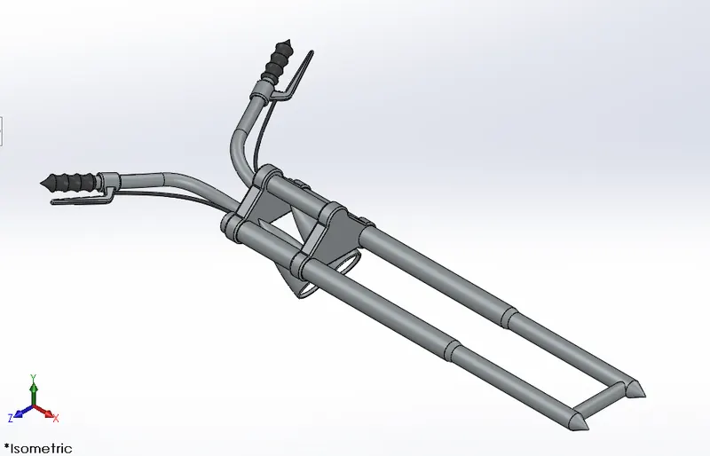
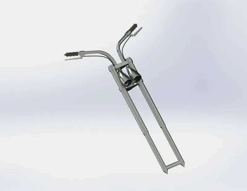
The front fork holds the front wheel, head lights, and the handle bar which enable the left-right movement of the front wheel and inturn turns the bike in the specific direction. The material used for the handle is glossy rubber, for the fork is Chromium plate and for the head light cover is a clear glass.
Tools & Features Used
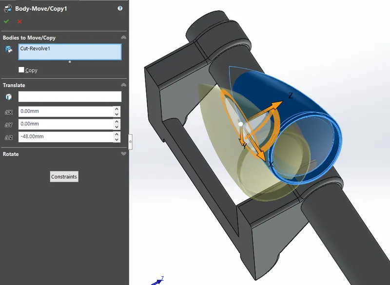
- Body Move/Copy
This enable us to move a body from its current position to an another by entering the x, y, z cordinates values. Here the head light housing is moved in -z axis about 48mm.
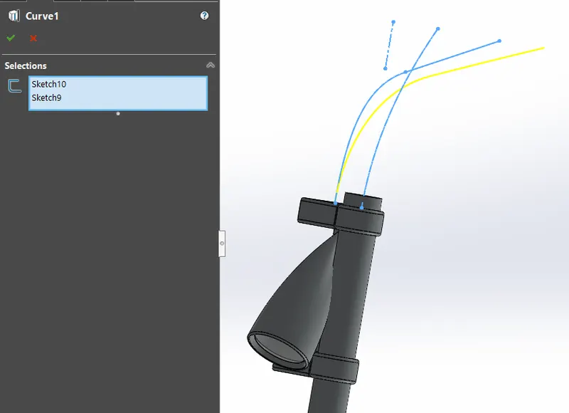
- Project Curve
The project cure feature will create a common cure which is reference with the two skeches in two different planes. Here the handle is a 3D cure which is resultant of sketch 10 and 9.
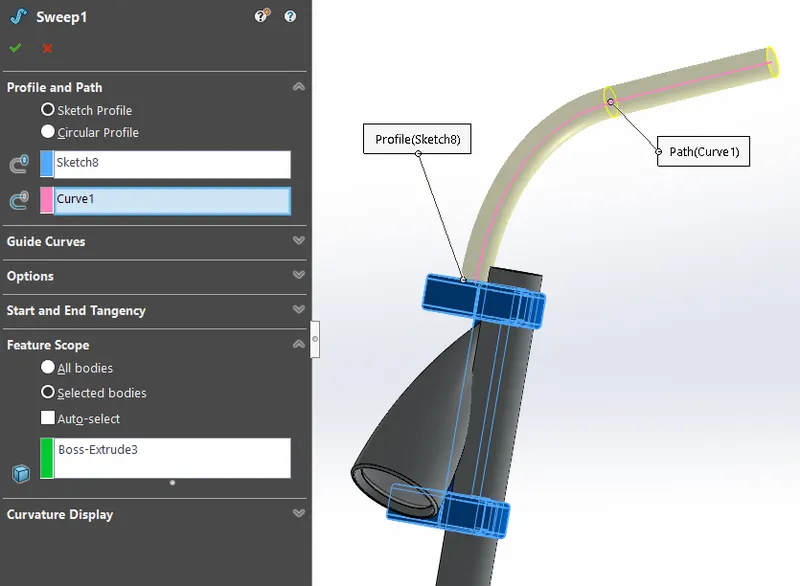
- Sweep
This feature will create a solid body with two parameters, a closed sketch and a curve. So a projected curve can be used to create a 3D sweeping extrude.
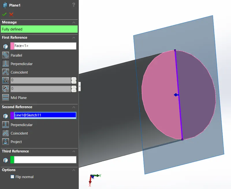
- Plane
A new plane can be created by using a reference plane and a line or an axis or even an another plane.
- Revolve
- Boss Extrude
- Fillet
- Linear Pattern
- Cut Extrude
- Dome
- Cut Revolve
- Mirror
- Combine
11. Chassis
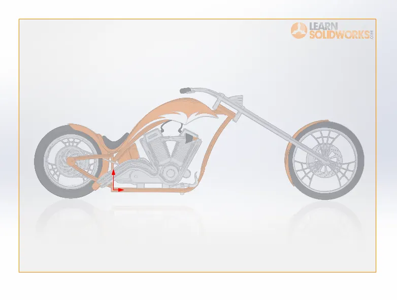
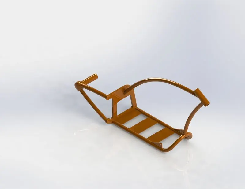
The chassis is the most important part in an automobile. The chassis performs the function of holding the other components and to give structural rigidity for the vehicle. The appearance of the chassis is siena.
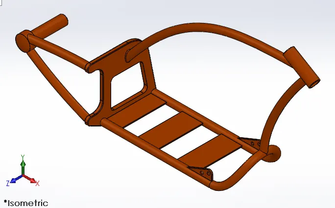
Tools & Features Used
- Sketch Picture
The function of this tool is to help us to create a sketch or a model with the help of a reference image also called as blueprint. We can change its size and give some transparancy so that the skeching will be easy to perform in both sides of the sketch picture plane.
- Project Curve
- Sweep
- Mirror
- Boss Extrude
- Cut Extrude
- Chamfer
- Fillet
- Plane
- Dome
- Split
- Combine
- Revolve
12. Engine
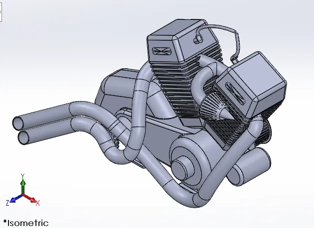
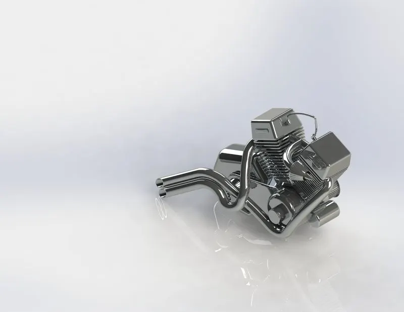
The engine is the heart of the bike. It provides power and torque by converting the linear motion of the piston after the combustive expansion of the fuel to rotational motion with the help of crank shaft. The material given to the engine is Chromium plate.
Tools & Features Used
- Composite Curve
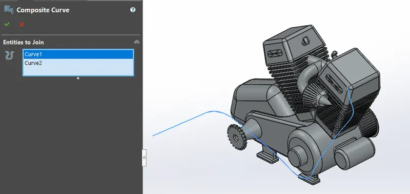
When there is two projected curve which was from two different sketches but they should connect so to make a continuous sweep to make a single curves. We can use composite curve for this function.
- Sketch Picture
- Boss Extrude
- Fillet
- Revolve
- Plane
- Circular Pattern
- Dome
- Cut Extrude
- Chamfer
- Plane
- Project Curve
- Linear Pattern
- Mirror
- Split
- Sweep
- Combine
13. Gas Tank
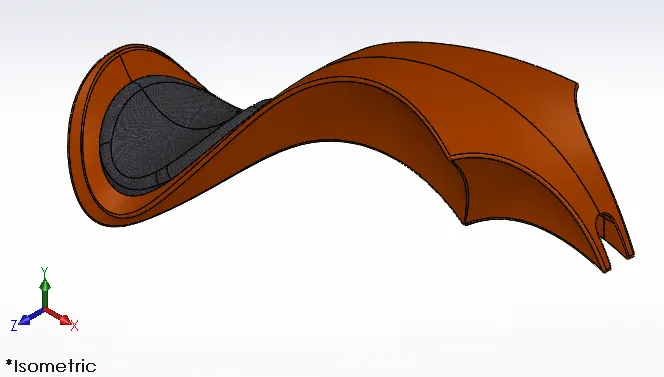
This gas tank model has two functions, one is to hold the fuel and the other is to hold a pillion seat. The appearance given to the tank is siena and the material for the seat is grey cotton.
Tools & Features Used
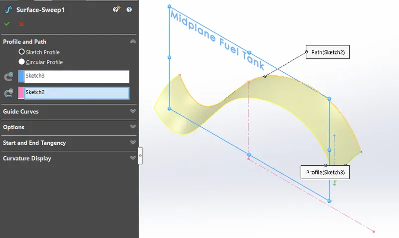
- Surface Sweep
With the parametres sketch profile and sketch path we can create a surface extrude.
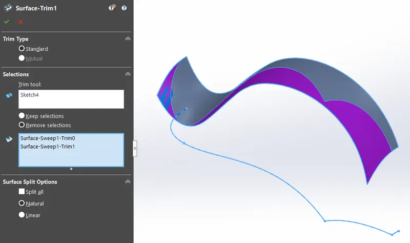
- Surface Trim
With a sketch, we can trim away selected sections of a surface.
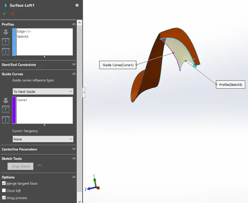
- Surface Loft
Like solid body loft, we can create surface with boundaries. Two adjacent profiles are selected and a guide curve acts as a boundary sketch.
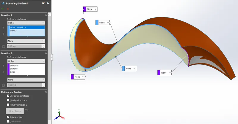
- Boundary Surface
The side of the gas tank is a challenging part to make into a surface. We divided the surface into two sections. The right most end has a sketch and a mid sketch and left side also have a closing sketch. In the boundary surface tool box, there is a direction 1 box in it the top and bottom curves were entered. In the direction 2 box the sketches that made the sketch into two sections were entere. These all parametere enabled the boundary surface work and output the desired surface.
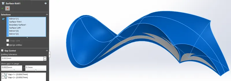
- Surface Knit
Knit surface convets the individual surfaces which have gaps in between them to a single connected surface .
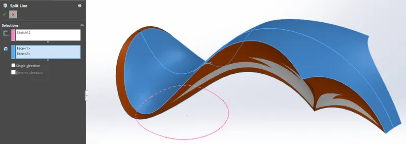
- Split Line
The seat sketch is to be projected from a plane to the curved surface of the tank, so the tool split line is used and the parameters are the sketch and the surface the sketch is to be projected.
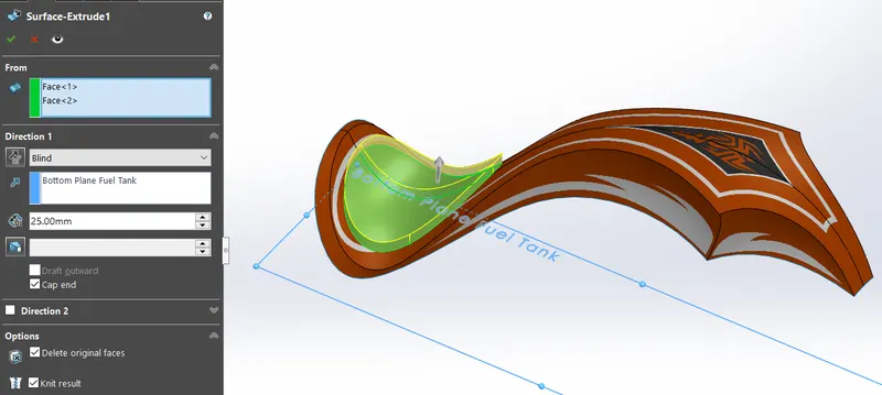
- Surface Extrude
The surface extrude a shelled varient of a boss extrude. Here we can use weather the top end should be caped or not and weather the bottom face should be present or deleted. We also can knit with in the tool box.
- Sketch Picture
- Plane
- Project Curve
- Mirror
- Fillet
- Shell
ASSEMBLY OF THE CHOPPER
The chassis is the part which is fixed in place and helps as a reference for mating other components. The only mirrored part is the pedal which was oriented correctly for proper placement.
Mates Used
- Coincident: This mates makes the selected entities on the same plane.
- Distance: We can set a distance parameter between two entities.
- Concentric: The selected circular edge or a vertex will have a common center after applying this mate.
- Limit Angle: It gives a component a rotational constrain by giving maximum and minimum angle.
- Width: It mates a component at a midpoint of another component by selecting two wnd faces.
- Angle: It gives an angular constrain between two entities.
- Parallel: It makes two entities parallely constrained.
- Tangent: A tangential relation is given to a circular edge and a line or a face.
Assembly Model Rendered Views
- Front View
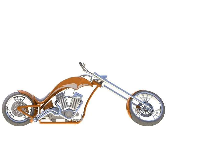
- Side View (Left Side)
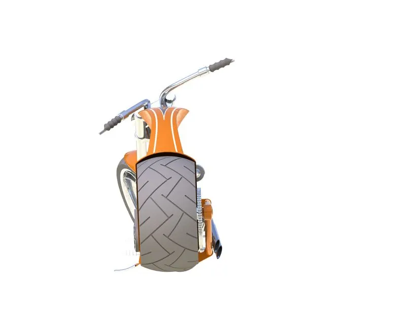
- Isometric View
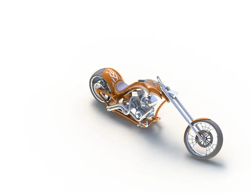
- Camera View
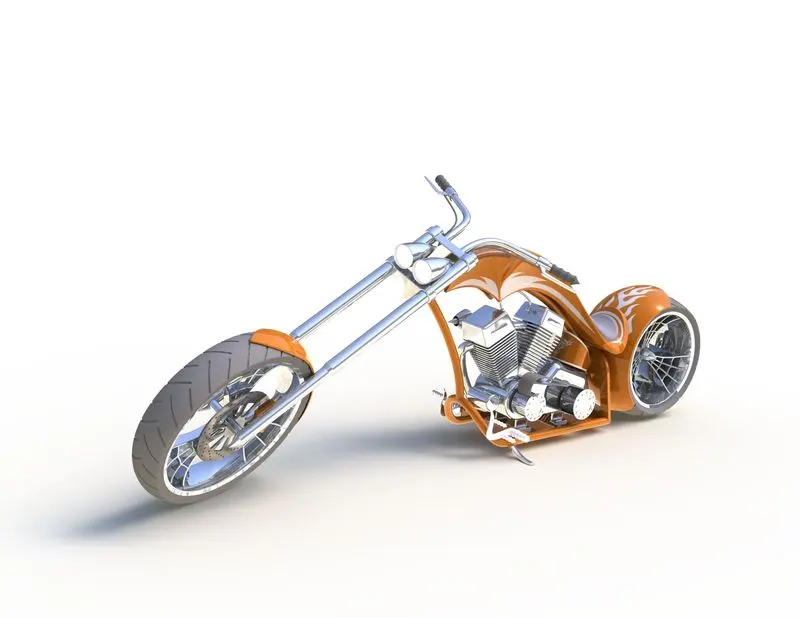
- Top View
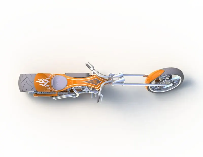
Rendered Parts
- Transmission Belt
- Kickstand
- Front Fender
- Rear Fender
- Chain
- Oil Tank
- Pedal
- Front Wheel
- Rear Wheel
- Front Fork
- Chassis
- Engine
- Gas Tank
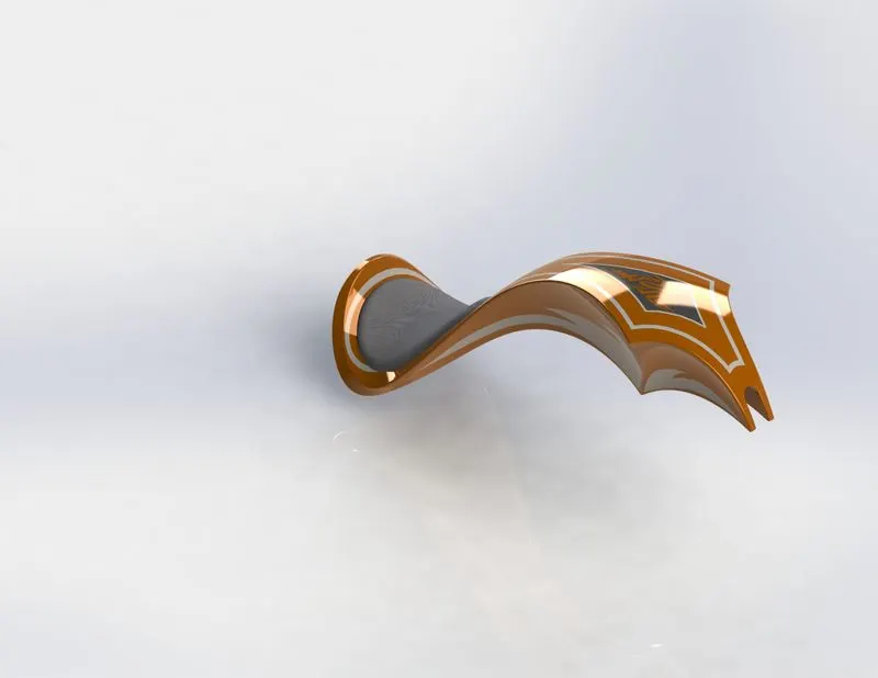
Rendered Images of Assembly with Scenes
CONCLUSION
After finishing this project, i understood the various tools and features and when and where to use them for sketching and modeling a component efficiently. Learned some tips and tricks. Performed adding decals, lighting and camera view to the American chopper and understood tools on how to make the model more realistic for a final render after adding scenes.