Radar Mast & Final Assembly of Yacht
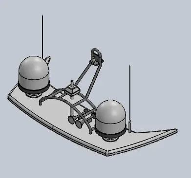
Radar mast:
Isometric:
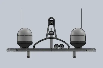
Front view:
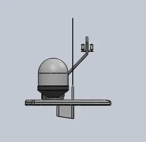
Side view:
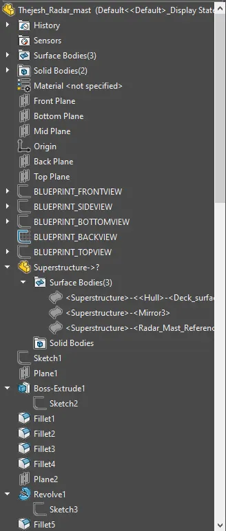
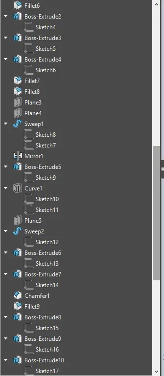
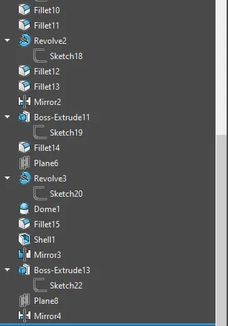
Modal tree:
DESIGN AND RENDERING OF SUNSEEKER PREDATOR YACHT USING SOLIDWORKS
Objective:
- To design various components of a Sunseeker Predator Yacht and to assemble them using proper constraints.
- To render the assembled Yacht using proper lightings, camera angle, and the background image as per the needs and provide a photorealistic image.
Introduction to Yacht:
Sunseeker International is a British luxury performance motor yacht brand. Sunseeker Yachts builds composite luxury semi-custom sport boats and performance motor yachts from 12.9 to 47.24 meters.
The Yacht is designed considering the major parts and it consists of the following.
- Propeller
- Radar
- Hull
- Front, middle and rear seat
- Garage door
- Superstructure
- Radar mast
The design phase consists of modeling each part with various sketch tools and features. Colour has been provided at the end to provide a realistic look for the parts after completion.
Design Approach:
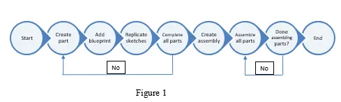
The design is done based on the Bottom-up approach where a blueprint is initially sketched as per the needs. A bottom-up approach is a traditional approach which deals with creating individual parts. Each part is properly modeled at its level and the will be added to the assembly by proper constraints. The design of the parts was performed by following the blueprint sketch. The below flowchart explains the design methodology clearly
Description:
The design of each part and the tools used for the design of American Chopper is explained below which is done in Solidworks and the rendering is done in Solidworks Visualize. For all the parts, a 2d sketch is a key tool to start the design.
Propeller:
A propeller is a device with a rotating hub and radiating blades, that, when rotated, exerts linear thrust upon a working fluid. The blades are specially shaped so that their rotation through the fluid causes a pressure difference between the two surfaces of the blade by Bernoulli's Principle which exerts a force on the fluid.
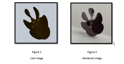
To design a propeller, we used tools like revolve, loft, circular pattern, extrude cut, and fillet.
- Revolve is used to make a propeller cap where the shaft assembles, which is done by providing an axis of revolution to a developed sketch.
- The loft is done by a couple of sketches which develops a blade for the propeller which spins around the axis of revolution.
- Extrude cut is used to cut the unwanted material from the cap.
- A circular pattern provides the desired number of blades around the axis.
- Finally, all the sharp edges are rounded using the fillet tool.
Radar:
Radar is used to detect obstacles and other ships around us. They are electronic navigation instruments that use a rotating antenna to sweep a narrow beam of microwaves around the water surface surrounding the ship to the horizon, detecting targets by microwaves reflected from them, generating a picture of the ship's surroundings on a display screen.
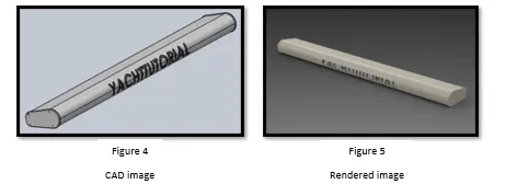
To design a Radar, we used tools like extrude and cut extrude, pattern, mirror, a split line, and fillet.
- Extrude uses a sketch to produce a 3-dimensional view of the radar.
- We develop one half and use the mirror tool to develop the other half.
- Cut extrude is used to develop the mounting of the radar.
- Using Split line, we can produce part markings to show the name visible.
- All the sharp corners were rounded finally.
Hull:
Hull is the base of the yacht and it carries the overall assemble. The hull consists of all the major components modeled in a single part. The chief parts that the hull consists of are the rudder, transom, helm, deck, bow, etc. This hull is built using surface features like a loft, extrude, trim, extend, offset, knit, fill, sweep, etc. and solid features like extrude, sweep, and many other tools. The building of the hull is explained below.
- First, the blueprint is developed for designing the parts as sketched for the appropriate location.
- The curves are developed using splines and lines in various sketches. Using a couple of curves, a surface profile is lofted. The process is continued many times to attain the shape of the blueprint as shown in figure 6.
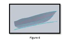
- After each and every extrude and loft surface the modal is trimmed to the desired shape and knitted to ensure the gaps are filled properly.
- After bringing the effective shape of the hull to one side, the part is transformed to solid while doing the knit operation.
- Handrails are constructed using a sweeping tool by creating proper planes and using the path of the sweep.
- Garage space is created by using extrude cut.
- Anchor is developed using several extrudes and chamfers.
- Linear patterns are made for some features to replicate the
- The propeller shaft is designed using revolve feature.
- After all the features were constructed, the part mirrored along the midplane.
- Finally, fillets are provided at all the required places and then colour is provided. The decals were provided for the deck and stairs.
Front, middle and rear seat:
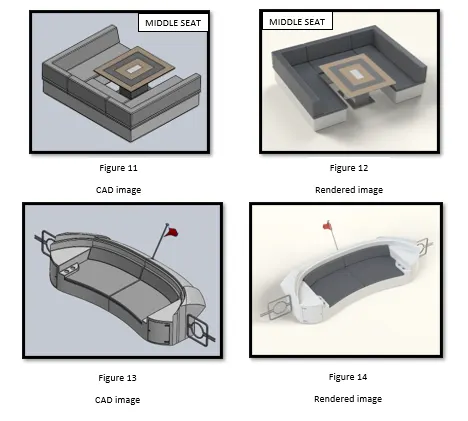
Seats are developed at the front, middle, and rear ends of the yacht. Each seat provides some wide views while traveling at the sea. The seats are developed using the reference of the hull deck. The features used to build the seats are surface sweep, extrude, trim, fill, knit, mirror, revolve, dome, fillet, chamfer, etc.
- The surface extrudes and a sweep was performed with the sketches to bring the shape of the seat. The unwanted surfaces are trimmed and then knitted to form a solid.
- The revolve is used to bring the shape of the seat.
- Dome is done at the top surface of the seats.
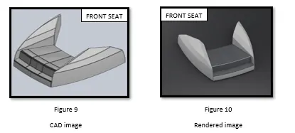
- Finally, the fillets and chamfers are provided for the sharp edges.
- The object is mirrored around the midplane to form the final seat.
- The colours are provided to them as per their needs.
Garage door:
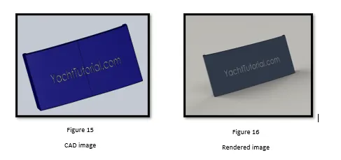
It is a normal door for the storage of goods. It is developed from the split block file of the hull. The design of the hull is done using extrude, shell, and mirror features.
- The split file is imported to the opened and the required cuts were made to make it look like a shape of the door.
- A shell is developed in the part and then it is mirrored over the other side.
- Then the required fillets were provided to avoid sharp corners.
- The part name bar is extrude cut to display the name.
Superstructure:
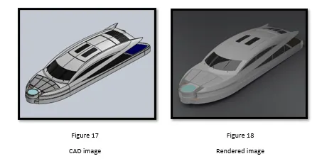
The superstructure is started from the surface of the hull. It uses a series of surface features to bring the required shape. It is a complicated feature as it uses a series of surface tools to bring the shape of the structure as per the blueprint. It uses features like surface extrude, sweep, loft, trim, fill, knit, extend, offset, etc. and solid tools like a dome, sweep, mirror, a split line, etc. The design process is explained below.
- The curves were created to provide a loft using the surface option. This will continue till we get a proper profile of the superstructure in the blueprint
- Once we attain the profile, we need to trim the unnecessary sections, knit the surface, and try to convert to solid.
- After converting to solid, we proceed with creating window profiles where needed. This is done by surface sweep.
- Then we split some lines to split the surfaces for aesthetics.
- Using extrudes we create steps and cut the unnecessary cross-sections.
- Once all the details were updated, we mirror the part and knit them to a single solid feature.
- Also, we will add handrails where needed using the sweep tool.
- Finally, we provide fillets and chamfers where needed.
Assembly of Yacht:
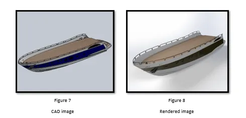
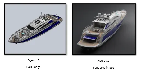
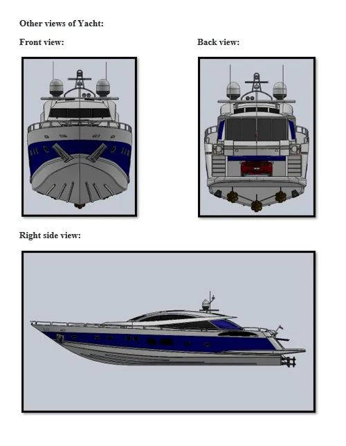
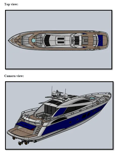
After completion of all the parts, we assemble them using the default constraint and some parts using manual constraint. The hull is placed first and then followed by other components. The assembly of the Yacht is then rendered as per the requirement.
Rendered Images:
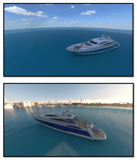
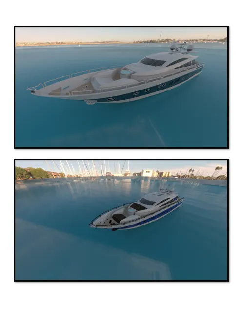
Rendering is done using Solidworks Visualize and the backgrounds were used to make sure it provides a realistic look with natural lighting and camera angles.
Conclusion:
- The parts of Sunseeker Predator Yacht have been successfully designed using Solidworks and it’s been assembled properly.
- The rendering of the Yacht has been done using Solidworks Visualize as per the requirement to make some photorealistic images.