Photo Realistic Rendering
DESIGN AND RENDERING OF AMERICAN CHOPPER USING SOLIDWORKS
Objective:
- To design various components of an American Chopper using various tools and sketches and to assemble them using proper constraints.
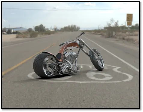
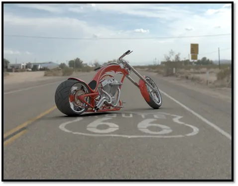
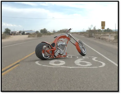
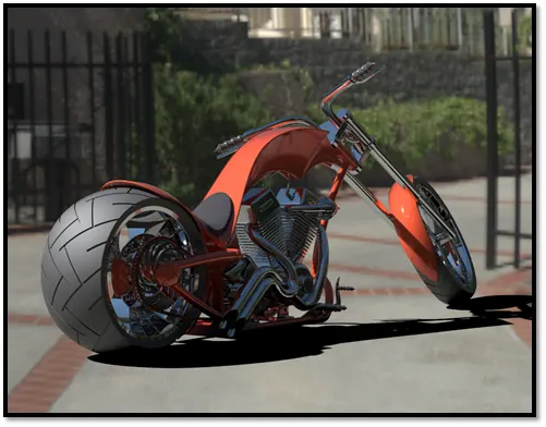
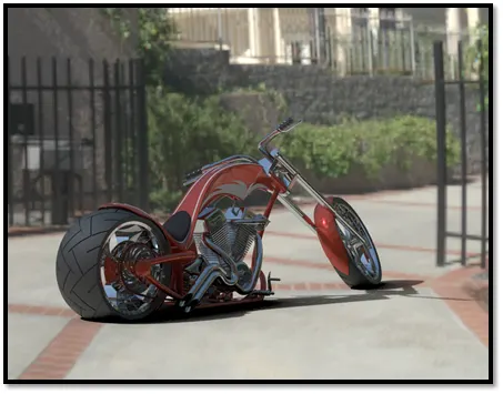
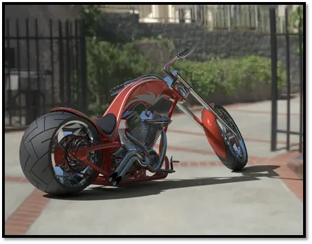
- To render the assembled Chopper using proper lightings, camera angle, and the background image as per the needs and provide a photorealistic image.
Introduction:
American Chopper is an innovative motorcycle designed and developed by Orange County Choppers. To design an American Chopper, we need to design the below parts in part modeling of Solid works.
- Transmission belt
- Kickstand
- Front and rear fender
- Chain
- Oil tank
- Pedal
- Front and rear wheel
- Front fork
- Chassis
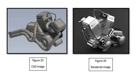
- Engine
- Gas tank
The design phase consists of modeling each part with various sketch tools and features. Material has been assigned at the end to provide a realistic look for the part after completion.
Design Approach:
There are two types of approaches to a design.
- Top-down approach
- Bottom-up approach
Top-down approach:
The top-down approach starts with creating an assembly with an assembly layout. The layout consists of creating a skeleton body in which the parts are constructed. The individual parts are created at the assembly level relative to other components. It is suitable for large assemblies.
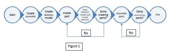
Bottom-up approach:
A bottom-up approach is a traditional approach which deals with creating individual parts. Each part is properly modeled at its level and the will be added to the assembly by proper constraints.
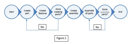
A bottom-up approach has been followed for the design of American Chopper. All the parts have been designed individually using different sketch tools and assembled finally.
Description:
The design of each part and the tools used for the design of American Chopper is explained below which is done in Solidworks and the rendering is done in Solidworks Visualize. For all the parts, a 2d sketch is a key tool to start the design.
Transmission belt:
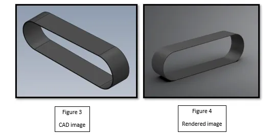
The transmission belt is the part that transmits power from one shaft to another. It transmits the power generated by the engine to the gearbox. The features used to build the transmission belt are sketch, offset sketch, extrude and fillet.
- The sketch is the basic tool to build a part to the required shape in 2d.
- Offset is used to create a boundary of the existing sketch inward or outward.
- Using extrude we convert the 2d sketch to 3d modal.
- Fillets are used to remove the sharp corners of the belt.
Rendering is done on Solidworks visualize with decent lighting.
Kickstand:
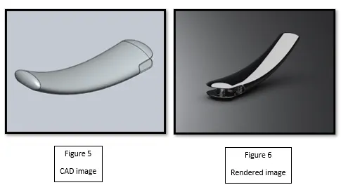
It is used to support the bike to the ground. For modeling a Kickstand, we need to use features like a loft, dome, extrude, extrude cut, fillet and split.
- First, we need to sketch a spline of the desired shape by providing proper angles and weights to constraint it. This spline serves as a path for the loft option. We need two sketches to describe the shape of the loft to the path it travels.
- Then, we need to proceed with using the loft option to bring the 3d projection of the stand.
- It is followed by the dome option to provide a smooth curvature at the end surface.
- A split tool is used to cut the material at the bottom to provide a flat base for the stand.
- The basic tools like extrude cut, extrude and fillets were used to make the required cuts and remove sharp corners.
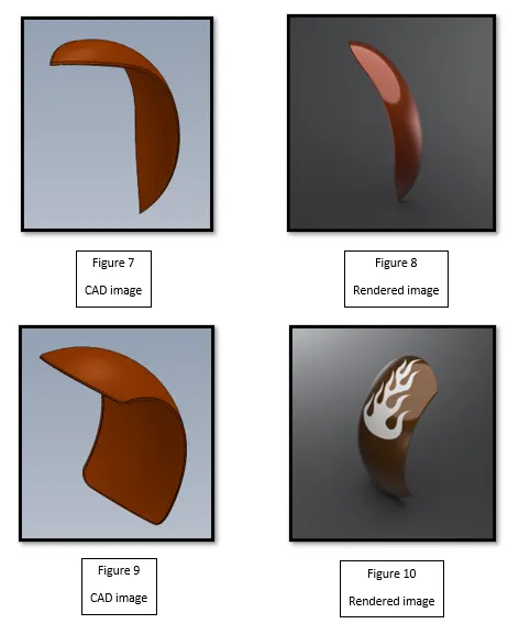
Front and Rear Fender:
Front and rear fenders are placed on the front and rear wheels to prevent the spray off of dirt, mud, water, etc. from tire.
The design of mud is done using revolve, split and fillet.
- Revolve is a feature that revolves the sketch at a fixed axis of rotation.
- Split is used to bring a required shape at the ends.
- It is followed by a fillet to remove sharp corners.
Chain:
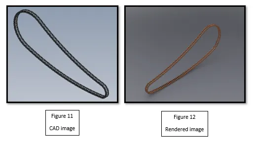
Chain is used to transmit power from the driveshaft to the sprocket. It is connected to the teeth of the gears and sprocket.
The chain is designed by the repeated process of extruding and pattern.
- The part traced by the chain is first sketched. Then, with the traced path we build and saved some 2d blocks which is used repeatedly for building a link.
- Extrude the required sketch and start building the 3d links.
- We pattern the links to the defined path to complete the chain.
- Fillets were used at right time and at the required places.
Oil tank:
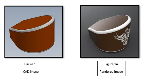
It is where the fuel is stored. The stored fuel will be sent to the engine when we start the bike.
The design of the oil tank is done using extrude, combine, fillet, and shell options.
- First, the tank is built with a couple of extrudes, and then using the common option we combine the potion which is linked.
- This effectively removes the uncommon portion of the extrudes and adds fillets where required.
- Then, we need to shell the modal to the required thickness.
Pedal:
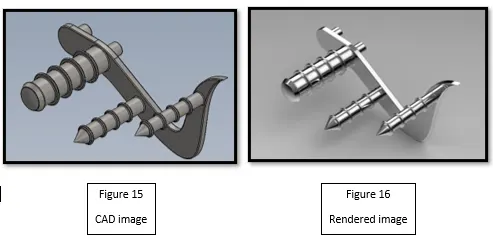
The pedal is where the footrests and the actual clutch for shifting gears are present. The pedal is designed with the extrude, revolve, dome, pattern, fillets, and chamfers.
- First, the bracket for the pedal is sketched and extruded.
- A sketch is revolved at its axis to provide the footrest. The ends are domed to provide smooth curvature.
- The features that need to be patterned were done at the end after the required fillets and chamfers were provided.
Front and rear wheel:
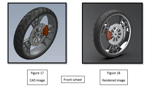
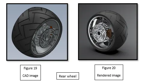
Wheels provide the connection between the ground and the chassis. The rotation of the wheels makes the movement possible. The wheel consists of the Rim, rotor, caliper, and tire. The rear wheel has a sprocket in addition. The design of the wheel is done by Revolve, Boss, and cut extrude, new planes combine, pattern, chamfer, and fillets.
- The Rim is made by revolving the sketch about the center axis. The circumferential support for the Rims was designed with boss and cut extrudes. The Rim is patterned about the center axis and then combines the three rims into a single body.
- The rotor is designed with extruding of the plate and then making the required cuts and holes using extrude.
- Caliper is designed with extruding at the side of the rotor and then provides proper chamfers and fillets to it.
- The tire is designed with the projections of the rim and then made some extrudes at the outer surface.
- The sprocket is the additional part of the rear wheel where the chain gets linked to the teeth. The teeth are cut to the plate of the sprocket and then fillets and chamfers were added to them and then we proceed with the pattern.
Front fork:
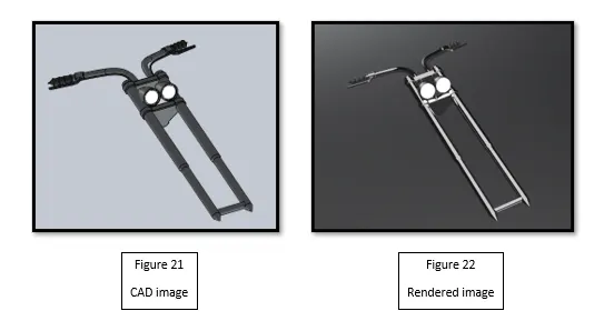
The front fork connects to the chassis and it connects the front wheel through the axle. The fork provides the suspension to the front wheel. The front fork has lamps, axle, handlebar, and fork. To design the fork, we need tools like extrude, revolve, pattern, body move, new planes, dome, sweep, curve, mirror, and combine.
- The intent is to design one side of the froe and mirror the other.
- The fork is revolved around the axis to have the desired length for suspension. The linear pattern is used to restrict the linear movement of the fork with the chassis allowing it only to rotate.
- Then, the lamps are designed using revolve, extrude cut and revolve cut for the dome look. It is moved to the required position using the body move option.
- The handles are created designed using a sweep by sketching the reference path and the cross-section for it. The grip for the handle is made using revolve.
- The fillets are added to the required edges of the desired radius.
- Once after completion of all the features, the fork is mirrored about the face and they are made into a single body using a combine.
Chassis:
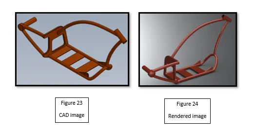
Chassis is the backbone of the chopper. All parts mount on the chassis and it connects the front wheel and rear wheel. The engine is placed at the bottom of the chassis. The design of chassis has sweep, mirror, extrude and cut extrude, split, dome, combine, curves and planes.
- The base outer profile of the chassis is designed by overlaying the blueprint of the chopper in the background.
- The 3d curves are constructed with 2d sketches to sweep as per the required profile.
- The required portions are extruded for the mountings of the engine, gas tank, front fork, pedal, etc.
- All the links are made using a sweep with a circular cross-section.
- The shaft and required support for the wheel are provided through sweep and extrude. Ensure the need to merge results while boss extrudes as it links all the features into a single body.
- Use dome at the rear wheel joint
- Use fillets where we don’t need any sharp corners.
Engine:
The engine is the brain of a chopper. It is mounted at the chassis. The power from the engine is transmitted to wheels through gears and chains. The engine consists of various features like extrude, revolve, pattern, mirror, composite curve, sweep, dome, etc.
- The base outer profile of the engine is designed by overlaying the blueprint of the chopper in the background.
- The engine is built with various extrudes and linear patterns for air ventilation. We also used drafts during extruding of the engine.
- The features like split and combine are used to remove and combine solids.
- The exhaust is designed with various curves and composite curves which provides a required path without interference.
- The curves for the exhaust are traced based on the background geometry and it needs to be tangential with feasible bends.
- The hoses were done using a sweep operation through which the fuel is sent to the engine.
- After the required features are done the engine is mirrored. This reduces the overall work.
- Once all the features are done fillets were used where needed to ensure the avoidance of sharp corners.
Gas tank:
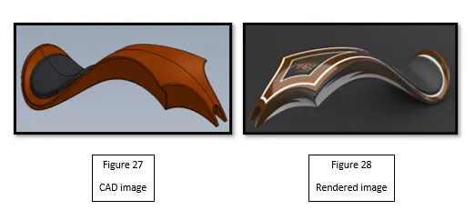
The gas tank mounts on the top of the chassis and provides the complete external structure of the chopper. It provides the exterior appearance of the chopper and contains the seat. The design of the gas tank is done on surfacing and it uses tools like surface sweep, surface trim, surface loft, surface knit boundary surface, a split line, and curves.
- The base outer profile of the gas tank is designed by overlaying the blueprint of the chopper in the background.
- Curves are created using multiple 2d sketches and are used to create a surface sweep, trim, and loft.
- After designing a proper tank, the surfaces are merged through surface knit.
- The seat is made using a split line and extrude and cap ends.
- Close all the open surfaces and add the required fillets.
- Use sweep for providing the mounting of the gas tank over the chassis.
- Use shell and give a required thickness.
- Customize the provided decals for the exterior images to bring more attraction to the gas tank.
Assembly: AMERICAN CHOPPER
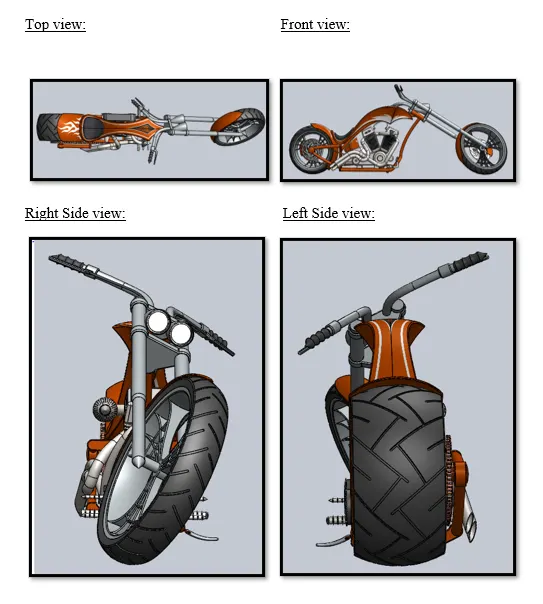
After designing the individual parts assemble all the parts using constraints like coincident, parallel, distance, tangent, etc., and provide a realistic look for the chopper. After completion of the assembly render the chopper with photo view 360 in the solid works. We can improve lighting, new cameras, real-time effects to bring more attractive images to the chopper.
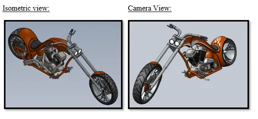
The lightings for the lamp can also be provided through photo view 360 to provide some realistic looks. They can be added to display states of the modal to provide different looks based on need.
Solid works Visualize Rendering with background:
Background: Route 66
Background: Sunny Driveway
Conclusion:
- The parts of the American chopper have been designed in Solid works with proper dimensions and been assembled with proper constraints.
- The rendering of the American chopper has been completed which produced realistic images with proper lighting and exposure.