Final Assembly of Yacht
MODELLING OF YACHT AND ASSEMBLING
OBJECTIVE:
To design, assemble and render a sunseeker yacht using solidworks.
INTRODUCTION:
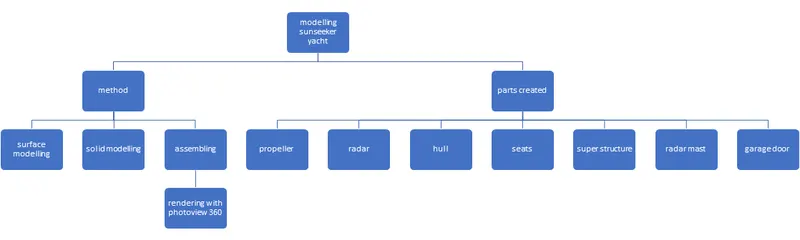
In this model, I have designed all the individual components of the yacht separately in the part file and then later assembled them together. In the end I used photoview 360 to create a final render of my model.
METHODOLOGY:
DESIGNING:
PROPELLER:
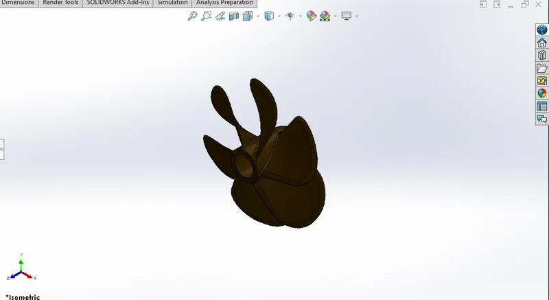
TOOLS USED: cut extrude, circular pattern, revolve, fillets, loft.
In this part we start by making the base sketch required to create a revolve. This revolve will act as the base for creating the blades of the propeller. Now we create a sketch of the blade and make a loft. Finally use the circular pattern option and pattern it. In the end use fillets to make the edges nice and smooth.
RADAR:
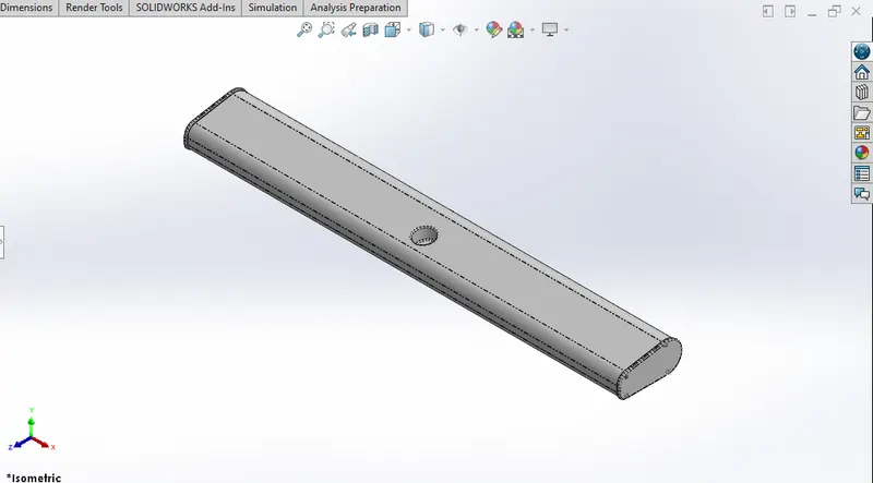
TOOLS USED: boss extrude, cut extrude, sketch pattern, fillets, mirror, split line.
In this part we start by making the base sketch required to make the boss extrude of the radar. Now we make another boss extrude to create the sides of the radar. At one side we make the holes using the sketch pattern and the cut extrude feature. Now mirror this onto the other side of the radar. Finally apply fillets to all the edges to make them nice and smooth.
SETTING UP THE BLUEPRINT:
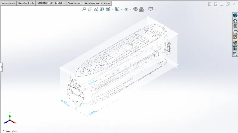
Here we make the foundation to create all the main components of the yacht. We arrange all the blueprints( side,top,bottom,front and back) in their respective planes. We do this so that it makes our work simple and easier to design the upcoming parts.
HULL:
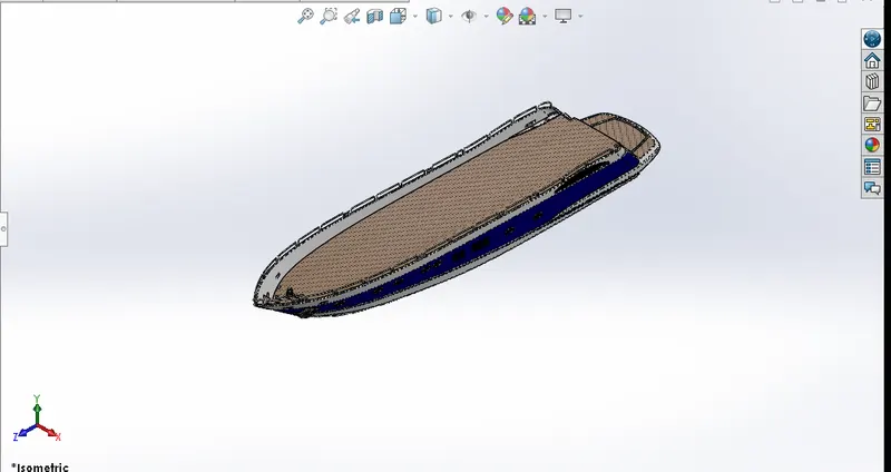
TOOLS USED: projected curve, surface loft, surface trim, surface knit, boss extrude, fillets, surface fill, shell, chamfer, cut extrude, sweep, dome, helix, linear pattern, mirror, split line.
This is the foundation of the yacht. We make this by making use of the blueprints. We start by creating two projected curves and then making a surface loft. Surface loft helps us to create a lofted surface with help of the sketch we make. Then we use the surface trim option which helps us in trimming off the non-required surfaces from our model. Later we also make use of the surface knit option which merges all the non-merged edges of the surface. When the color of the edge turns black from blue, it means that the surfaces are knitted properly without any issue. As we continue with the model, we make use of the surface fill option which is used to fill the gaps between the surfaces. The shell feature is used to convert the hull into a hollow shell. As we proceed, we use the helix/spiral option to make a spring like structure which acts as a pipe in our model. We also use the boss extrude and cut extrude option while dealing with the solid bodies. The chamfer is used to make an angled/uneven surface with required dimension. We make us of the split line feature to split the hull into different parts. Finally using the mirror option, we mirror the hull.
MODELLING OF FRONT, MID AND REAR SEATS.
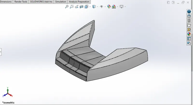
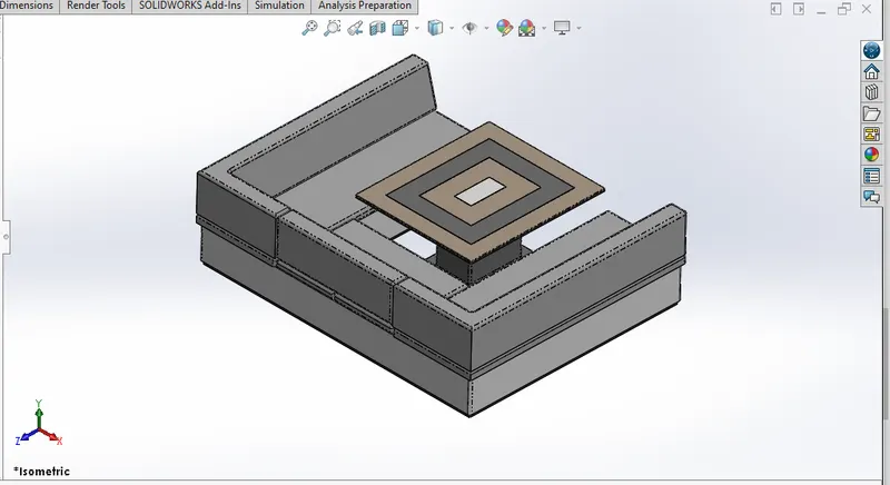
TOOLS USED: boss extrude, surface sweep, surface knit, cut extrude, surface trim, fillets, surface loft, chamfer, dome, mirror, surface offset.
Here we create the seats of the yacht. We make use of the surface sweep and surface extrude to create the flat/curve surface required for our seats. We make use of the surface trim option to delete the extra extended surfaces. Once the surfaces are created properly, we knit them using the surface knit option. Apply fillets to all the edges of the seats to make it nice and smooth. Apply dome to make a hollow spherical surface. Use the boss extrude and cut extrude feature to create and cut the solid bodies while the making of the seat. The surface offset feature is used in rear seat, which is used to offset a selected surface to the mention distance. Finally mirror the seat using the mirror option to get the full seat.
SUPER STRUCTURE:
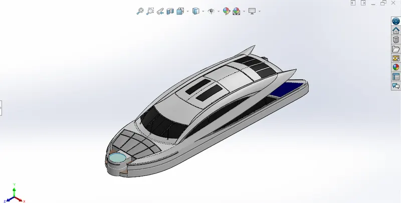
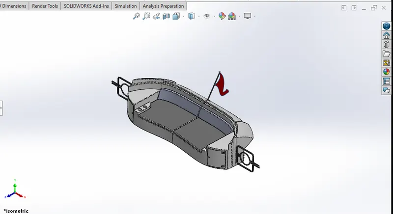
TOOLS USED: boss extrude, cut extrude, surface loft, surface extrude, trim, extended surface, swept surface, projected curve, fillets, surface knit, ruled surface, mirror, chamfer, 3D sketches.
For this we highly make use of the blueprint setup. We start by using the surface extrude feature to create bottom of the structure with the help of a 2D and 3D sketch. Further we make projected curves and loft the surfaces. As we move further we create 3D sketches and make a surface sweep. The extra extended surfaces will b trimmed using the surface trim option. After each surface is created properly we knit the surfaces using the surface knit option. We also make use of the extended surface option to extend a particular surface when needed. We make use of the boss extrude and cut extrude while the making of the jacuzzi and the front seats. Apply fillets to all the edges to make the edges smooth. Once the structure is completed, we mirror it to get the complete the superstructure. Later we create the windows and the front wipers for the model using boss extrude, cut extrude, sweep, fillets and chamfer.
RADAR MAST:
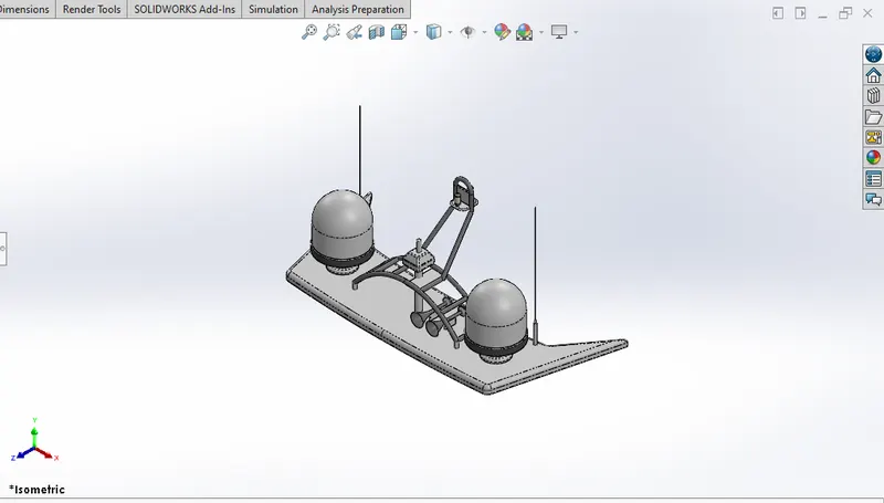
TOOLS USED: boss extrude, cut extrude, revolve, fillets, chamfer, mirror, shell, dome, sweep.
We start by creating the bottom surface of the radar mast using the boss extrude feature. Then use the revolve feature to make the dome like structure. Now create the antenna using the boss extrude feature. Create the horn using the revolve feature. Once all of it is done, mirror the radar mast excluding the horn to get the full model. Now separately mirror the horn beside it to finish the radar mast model.
ASSEMBLING AND FINAL RENDERING:
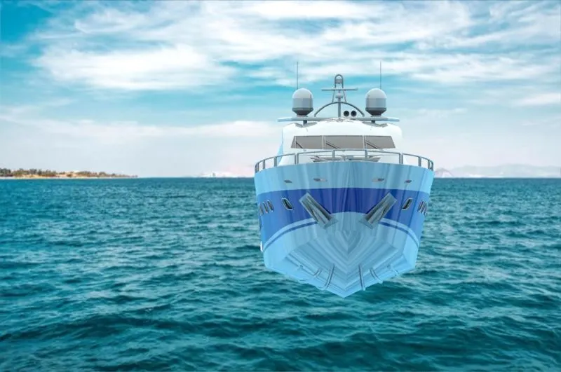
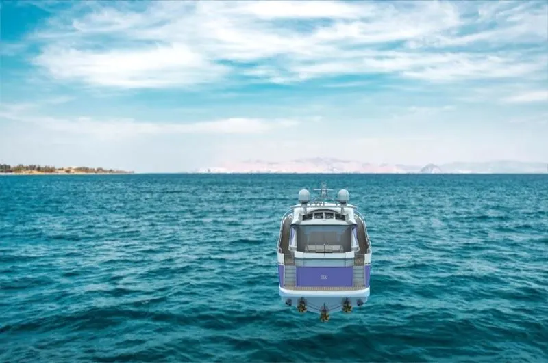
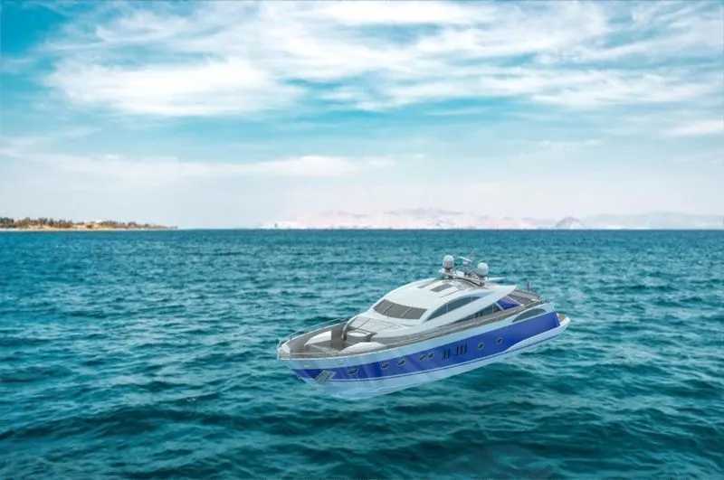
First, Import the hull and fix it. Now add the other components and give the appropriate mate relations to fully assemble the model. Once the assembling the done, use the photoview 360 to render the yacht and get a final preview of it.
assmebly images without rendering:
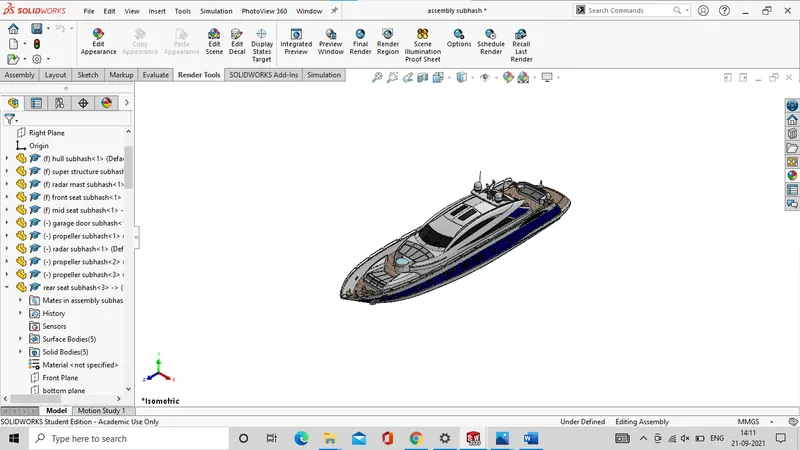
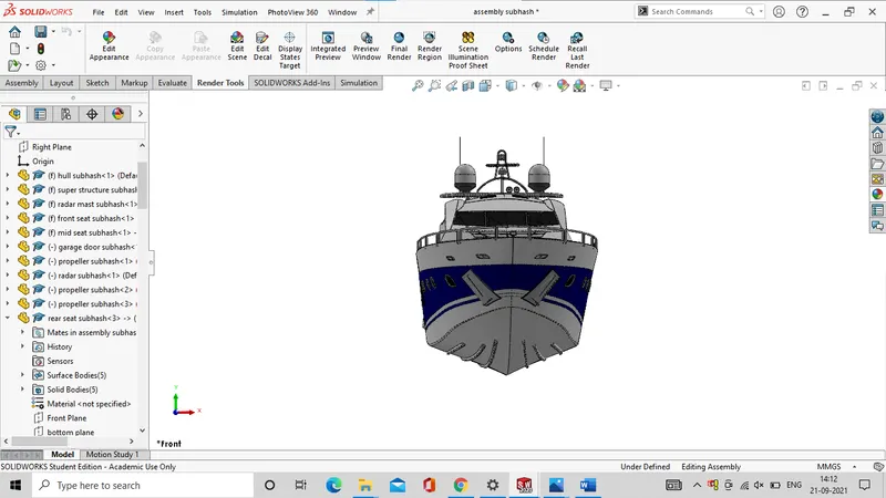
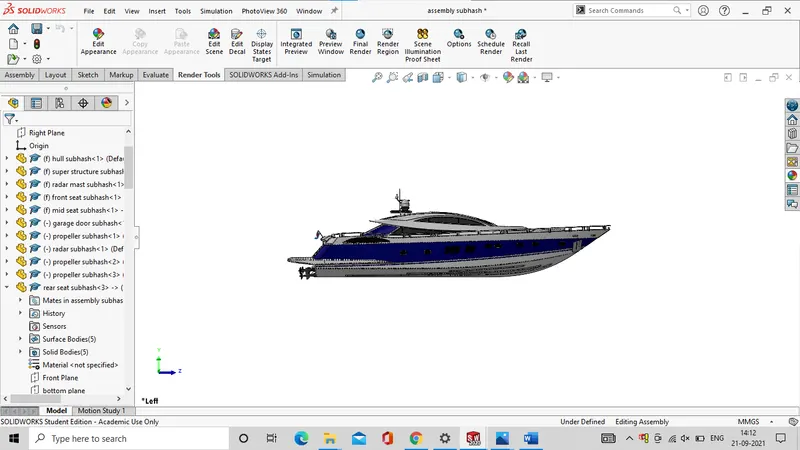
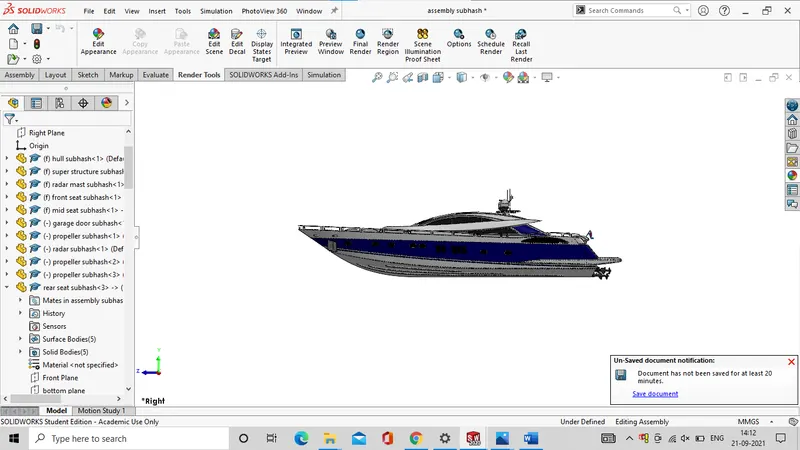
rendered images are shown below
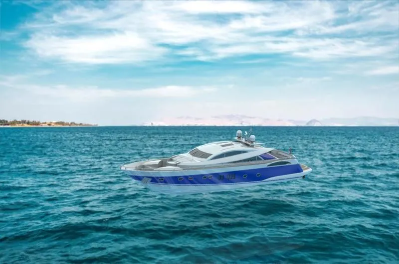
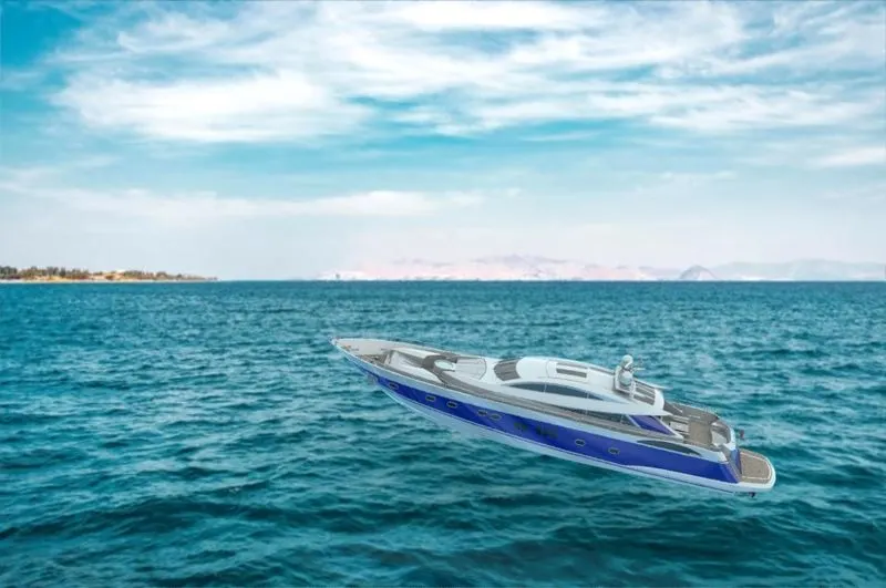
CONCLUSION: The yacht is assembled and rendered successfully.