Radar Mast & Final Assembly of Yacht
Report on Sun Seeker Predator Yacht
Objective:
To design individual parts of the yacht with fully defined sketches and appropriate appearances.
To assemble all the individual parts of the yacht model by assigning suitable constraints.
To render the yacht model by adding appearances, decals, lights, cameras, and background scenes.
Software's Used:
Solid-works 2020
Solid-works Visualize 2020
Introduction:
Solid-works: Solid works is a product of Dassault systems. It is a software used for designing, assembling and real time rendering of the real time models. Any kind of complicated and sensitive designs can be easily modeled using the tools and interface of this software. The basic tools and its usage are explained in the description section
Yacht: A yacht is a Watercraft used for pleasure or sports. The term originates from the Dutch word yacht (which means "hunt'), and originally referenced light, fast sailing vessels that the Dutch Republic navy used to pursue pirates and other transgressors around and into the shallow waters of the Low Countries. The yacht was popularized by Charles ll of England as a pleasure or recreation vessel following his restoration in 1660.
Today's yachts are almost exclusively for leisure A yacht is any sail or power vessel used for pleasure, cruising, or racing. The word often connotes luxury; however, luxury is not a quality necessary to meet the definition, nor is it always desirable. Many racing yachts are stripped out vessels with a minimum of accommodations to lower weight. The term 'sailboat' or 'sail yacht' is used in America to differentiate from a powerboat' or 'power yacht' As of December 2018, there were about 6,500 yachts over 24m on the market.
Design methodology Flowchart:
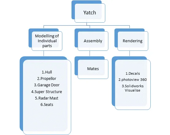
Design Process
The entire modelling process is divided in to Six Stages
- Blue Print Setup & Creating Planes.
- Modelling of Hull Part
- Modelling of Super Structure
- Modelling of Radar Mast
- Modelling of front, middle & Rear Seats.
- Assembling the individual parts.
Parts of yacht
- Hull
- Superstructure
- Radar mast
- Rear seat
- Middle seat
- Front seat
- Radar
- Garage door
- Propeller
Commands Used:
- Line: This feature allows us to create a straight line. The line can be a solid line or
- Circle: This feature allows us to create circles.
- Rectangle: This feature allows us to create squares or rectangles.
- Spline: This allows us to make curved lines
- Curve Projection: this is used for the projection of the curves made in different planes to create an intersected curve
- Arc: This allows us to create arc.
- Projected Curve: It is a very powerful tool which can project two different 2D splines from two different planes into a single spline or a curve in 3D which can meet our need. It is the most often used feature before creating any surface.
- Split: This feature is used to split to bodies using a sketch
- Trim: This is used to trim sketches.
- Extend: This feature allows us to extend the sketches
- Extrude Bose: This feature allows us to create solid bodies.
- Extrude cut: This feature allows us to create cuts or holes of any shape in the solid body.
- Swept Bose: This feature allows us to make a solid body along a curve path or create a curved solid body.
- This feature allows us to create exact copy of the solid body using a reference plane or face.
- Revolve: This allows us to create revolve solid body around an axis.
- Linear Pattern: This allows us to create a pattern in a straight line.
- Circular Pattern: This allows us to create a pattern in a circle
- Fillet: This is used to create circular edges.
- Chamfer: This is used to create inclined edges.
- Plane: This feature is used to create new planes.
- Loft: This feature allows us to make solid bodies with uneven geometry,
- Dome: This feature is used to make a dome shaped solid over a flat solid body.
- Shell: This is use to make a hollow solid body
- Mirror Entities: This is use to create a mirror of sketch.
- Split Entities: This is used to split a line into two or more parts.
- Split line: the Split line is used to divide parts into multiple bodies. You can use the Split line feature to save the new bodies when you split the part or use the Save Bodies to save them after the split is complete.
- Convert Entities - Converts selected model edges or Sketch entities into Sketch segments, Loft this is creates a feature by making transitions between profiles. A loft can be a base, boss, cut, or surface. We can create a loft using two or more profiles. For a solid loft, the first and last profiles must be model faces or faces created by split lines, planar profiles, or surfaces.
- Fillet: this is creates a rounded internal or external face on the part. We can fillet all edges of a face, selected sets of faces, selected edges, or edge loops. • Helix: this is create a helix or spiral curve in a part. The curve can a lofted feature be used as a path or guide curve for a swept feature, or a guide curve for.
- Loft Surface: Loft Surfaces are surfaces generated by multiple 3D Curves or existing edges creating a smooth tangent between the selected curves.
- Surface trim: It is used to cut away material from a surface, and provides two modes: Standard and Mutual. Extend Surface it is used to extend the surface which is already created. There are different options available on the extended surface. We can extend the surface as same surface or we can extend the surface tangent to the surface.
- Surface knit: It is used to knit the two free edges/open edges of the surfaces together Also it reduces the gap between the two edges of the surface.
- Sweep Surfaces: This is surfaces that are generated from a section curve positioned along a path.
- Filled Surface: This Surface feature constructs a surface patch with any number of sides, within a boundary defined edges, sketches, or curves, including composite curves by existing model
- Ruled surface: It is used to obtain the extruded surface perpendicular to the plane and can be titled in certain angle.
- Rollback: Rollback is yet another powerful tool that allows going back to any phase of design in case if we need to edit or add some features later. We can use roll-up bar while removing errors too. This reduces the rebuild time and avoids further errors in the children features.
- Combine
- Combining Bodies - Add:
In a multibody part, you can combine multiple bodies to create a single
- Combining Bodies - Subtract:
In a multibody part, you can subtract one or more bodies from another body • Combining Bodies
- Common:
In a multibody part, you can create a body defined by the intersection of multiple bodies.
- Combine Property Manager:
In the Combine Property Manager, you specify which bodies in a multibody part to add, subtract, or overlap.
- Delete/Keep Body:
You can select bodies to keep or delete using the Delete/Keep Body feature. This is useful in working with multibody parts with multiple configurations.
Design and Methodology
- Blueprint Setup
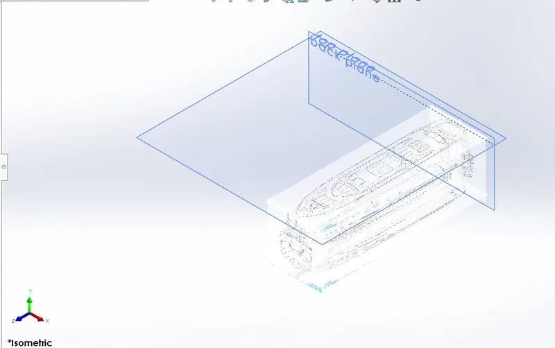
Blueprint is basically a design plan or technical drawings of different orthographic views of a product. The main motto of the blueprint is to bring out the exact same shape and form of the product as designed by a designer. It also the accuracy and the proportion of the product. Designing a product without a blueprint may lead to multiple errors, unnatural proportions and improper dimensions. A proper blueprint setup omits all those problems. To set up a blueprint, we use sketch mode in SOLIDWORKS in each plane. In this case, the images provided for the front view, side view, top view, back view, and top views are added in respective planes. One very important thing to note while setting up a blueprint is the size of it. all the parts are going to be designed laying up the blueprint and taking its reference, it is very crucial to maintain the correct and real size of the blueprint in the very first step. It can either be adjusted manually with the dimensions or by adjusting the scale bar.
Methodology
- Select a Plane & select a 2d drawing option & go to Tools- Sketch Tool-Sketch Picture.
- Browse the Image & change the dimensions as per requirement & use transparency tab & chose full image for convenient sketching & name the views
- Repeat the above steps & name it as Front view, side view, Top view, Back view.
- change the names of the planes as front plane, bottom plane & mid plane & Arrange the blue prints in a sequential order.
- Hull:
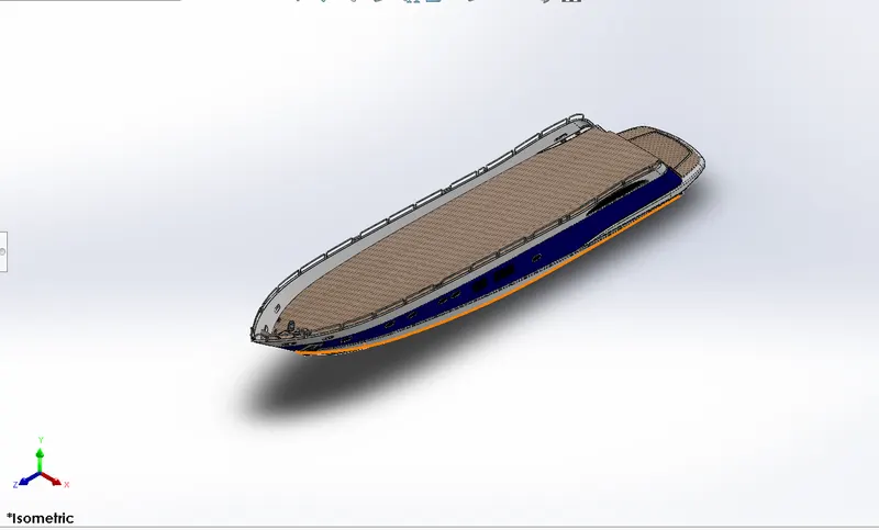
A hull is the watertight body of a ship or boat. The hull may open at the top, or it may be fully or partially covered with a deck. Atop the deck may be a deckhouse and other superstructure, such as a funnel, derrick, or mast. The line where the hull meets the water surface is called the waterline.
Hull is the main part of the Yacht. It is the giant component which extends 108ft long. It is the structure which holds all the other components of a marine vehicle. It is the part which is enclosed and water-lift is created for the movement of the vehicle on the surface of the water. The curves are sketched as close as the blueprints from 2 different views and are projected to form a 3D curve. 3D sketches are also used in this part. The Hull for this Yacht was created using the surfaces made out of the projected curves using the blueprints sketches. It consists of parts
like railings, bow, deck, pulpit, anchor, garage, windows, etc There is a wide variety of hull types that are chosen for suitability for different usages, the hull shape being dependent upon the needs of the design. Shapes range from a nearly perfect box in the case of scow barges, to a needle-sharp surface of revolution in the case of a racing multihull sailboat. The shape is chosen to strike a balance between cost, hydro static considerations (accommodation, load carrying and stability), hydrodynamics (speed, power requirements, and motion and behaviour in a seaway) and special considerations for the ship's role, such as the rounded bow of an ice breaker or the flat bottom of a landing craft.
Features used to create the Hull
o Sketch
o Offset
o Entities
o Project curves
o Lofted Surface
o Trim surfaces
o Extruded Surface
o Knit Surface
o Filled Surface
o Shell
o Extruded Boss
o Extruded cut
o Fillet
o Chamfer
o Swept Boss
o Revolved Boss
o Dome
o Helix
o Linear Pattern to Delete Face
o 3d sketch
o Mirror
o Split Body
o Offset Surface
Methodology
- Blue Print setup - Insert all views like Top view, Side view, bottom view, front view, etc. by giving proper X,Y & Z - Create two new planes Back Plane and Top Plane using Front & bottom plane as references. direction - Bottom Plane - Draw a Horizontal line and a spline with midpoint, give relations and dimensions to make it fully defined dimensions to it.
- Mid Plane - Draw a Inclined line in-z direction, vertical centre-line and a spline blue print
Create a Projected curve using above two sketches with 2 midpoints, drag the arrows to make sure it matches
- Similarly create one more projected curve by drawing sketches on Mid plane & Bottom Plane using lines and splines
- Back Plane - Draw a spline and use pierce relation to connect with projected curve.
- Mid Plane - Draw one more spline and use pierce relation again. Now create a lofted surface using above two sketches
- Similarly create one more surface loft by drawing sketches on Midland and Back Plane using splines. - In order to trim extra surface draw a vertical line in Mid plane and trim extra portion
-Mid Plane - Draw a spline parallel to surface loft and do surface loft. - Mid Plane - Draw a horizontal line and vertical line do surface extrude.
- Trim Extra surfaces an knit them together
- Make sure all lines turn out to black colour which indicates proper knitting - In order to fill the gap use Filled surface by drawing a sketch on Mid Plane
- Now Knit Surfaces and create Shell.
- Mid Plane - Offset created surface entities inwards and draw a line to make closed
surface. Trim extra entities using Trim entities and extrude it.
- Bottom Plane - Draw a sketch using 2 splines and do cut extrude. - Apply Fillets and Chambers to respective edges.
- For Side Windows - Draw four lines as a rectangle on Plane 1 and apply fillets to corners, do linear pattern. Remove extra created Window & do cut extrude and create a cut extrude
- For Port holes - Draw a straight slot on Plane 1, copy the slot to another port hole using copy feature as per blue print Create a 2D Sketch in new plane by drawing a circle and for profile create a 3D Sketches by converting sweep. Repeat similar steps for creating remaining forth holes.
- For Lower Deck - Create a sketch on Top Plane as per Blueprint using Splines, lines and do extrude, forth holes entices. Now for
- Staircase - Crest a sketch on Top Plane by drawing line in rectangle shape and do cut extrude. Select the extruded right face create a solid and draw few connecting horizontal and vertical lines in the form of stairs, extrude it Up-to next/Up-to surface.
- For Lower Portion of Hull - Create a plane at an offset of 3000mm from Bottom Plane Draw 3 splines and drag their arrows to match as per blueprint Offset the splines and make it closed by drawing lines, extrude it.
- Anchor House - Draw a sketch on Top face of Hull using two circles and connect them with lines and trim the inner half of circle to create a lower surface of Anchor house. Draw a vertical line & horizon line on new plane using previous sketch as reference and revolve it. Create a sketch by drawing lines and circles, extrude it. To remove some portion from previous extrude, create a sketch and do cut extrude.
- For Rope - Draw a helix and create a plane using helix as reference, draw a circle at the end point of helix. Using Helix as path and circle as profile do sweep. Create one more sweep to connect the rope from house to created helix - Create some extra forth holes at front end and rear end with the help of few sketches and extrude them, use linear pattern accordingly to pattern them
- For Hand railing - Create a new plane offset from left face of stair connected portion Draw a sketch by 3 Point Centre rectangle and apply fillets to two top comers. Create one more plane using lower left end point of rectangle and draw a circle Now Sweep using Circle and rectangle as profile & path respectively.
- For Side Railing - Draw a sketch on Mid Plane by offsetting inner edge of Hull inwards and outwards respectively. Draw few vertical lines as per blue print and trim the unwanted portion, so that it will form a chain, apply fillets to end portion and draw one more sketch in respective plane were offset the inner edges of hull Now create a projected curve using above two sketches. Create a new plane at the end of created sketch for railing reference and draw a circle sweep by using circle and projected curve.
- For Caliper - Draw a sketch on Back Plane using few lines and extrude it, to develop caliper surface. Select the surface of Caliper draw a sketch as per blueprint & revolve it.
- For Propeller Shaft - Create a sketch on Back face of Hull by drawing lines as per blue print and revolve it Pattern it accordingly with the help of Pattern direction sketch.
- For Connecting Rod - Draw a 3D Sketch using line to connect both Propeller shaft holes & extrude it.
- For Anchor - Draw a sketch on Mid plane at front portion of Hull using lines and splines as per blueprint and extrude it and mirror it across respective face
- For Garage Door - Draw a sketch on Mid plane by drawing a comer rectangle & do cut extrude, sketch extrude left face and sketch on it by converting previous sketch as entities create cut extrude. Now use split and remove the appropriate portion and save it as Garage door. - Create a pin by drawing circle on previous extruded face, extrude it.
Create a new sketch on Mid Plane by drawing Splines and offset in upward and downward direction. Use Split line and select all faces to split.
- Now give appearance to Hull, windows, Railings, Caliper, Anchor, etc.,
- Finally mirror the whole body across Mid Plane and check all appearance are applied correctly
- Superstructure
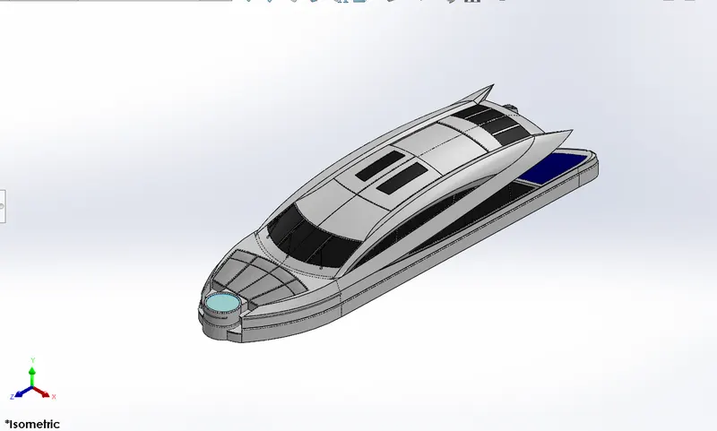
A superstructure is an extended construction of any building or platform that rises above the rest of the building or platform in a distinct manner. The word comes from a combination of two Latin words, the Latin prefix 'super means in addition or above or in excess of whereas the stem word structure means to build or to heap up. Thus, superstructure means to add a construction to an already existing structure. In ships this is the name given to the part of the ship that emerges from the deck. However, any mast, sails, any armaments or arsenal are not included in this category.
The size of the superstructure has a great influence on the mobility of the vessels. They are designed in a manner, so that, they add value and hinder the speed and mobility in the least. The superstructure is mostly designed in fashion as well. This is because it is the most easily visible part of the ship, in fact it is the identification of the ship, and so the designers try to provide it with the identity that is unique.
It is the part that sits on the deck surface of the Yacht. In general, the superstructure of a Yacht consists of cockpits, mast, tables etc. For the modelling of this superstructure, the deck surface was used as the base so it directly inserted and fixed in position in the assembly. The curves are sketched as close as the blueprints from 2 different views and are projected to form a 3D curve 3D sketches are also used in this part. Windows and the windscreen wipers are also included in this part. Back doors and the windows are provided with dark coloured glass.
Features used to create the Superstructure:
o Line
o Spline
o Circle
o Extrude cut
o Projected curves
o Offset
o Surface fill
o Surface Extrude
o Surface sweep
o Dome
o Surface Trim
o Extend Surface
o Surface Knit
o Plane
o Ruled Surfaces
o Split Entities
o Split Lines
o Delete Faces
o Fillet
o Chamfer
o Mirror
Methodology
- Blue Print setup - Insert all views like Top view, Side view, bottom view, front view,etc.. by giving proper X,Y & Z direction
- Create two new planes Back Plane and Top Plane using Front & bottom plane as references.
- Insert the Hull part by selecting the surface bodies.
- Create a sketch on Deck Surface by drawing a two Splines and a line as per blueprint and extrude the surface.
- Create a Plane at the end of Create surface Extrude.
- Create a surface sweep by drawing sketches on created Plane using line (Horizontal) and apply pierce reaction with extruded sketch by convening Outer surface as entities. - Extend the Outer edge of surface using Ruled surface at an angle and trim the extra surface. Knit all the surfaces dimensions to it surface.
- Create one more Projected Curve by drawing-two sketches on respective Planes using Splines and lines which is further used in creating Lofted Surface
- Create one more surface sweep by drawing sketches on created Plane using line(Horizontal) and apply pierce reaction with extruded surface. A 3D sketch by convening Outer surface as entities.
- Trim the surfaces which are not required by drawing sketches on respective faces/Planes.
- Create a Swept Surface by drawing a sketch - Trim the extra surfaces on Mid Plane using Splines and a 3D Sketch by converting respective edges.
- Similarly, for creation of surfaces on Top, draw two sketches on respective Planes to get Projected Curve as per Blue print which is further used to create Lofted Surface.
- For Side Windows Select the outer surface of Super structure use Ruled surface for extension. Trim the Extra surfaces.
- Select the Deck face and create a sketch by drawing a line at rear portion and do Surface extrude. Trim extra surfaces and Knit all together.
- For Front Portion - Draw a sketch on Mid Plane by converting respective edges and do surface extrude. Trim extra surfaces and Knit all thereto. Create one more sketch on Mid Plane by drawing line and spline and do surface extrude.
- Select the deck surface and create a sketch sketch by drawing a circle at a distance from above surface extrude. Extrude it and draw a circle at on extruded face to perform cut extrude. Draw two more circles on extruded face which are again to be extruded. Apply fillets to respective edges. In order to remove extra portion draw a rectangle on deck surface do cut extrude. Use Delete face option to remove respective faces.
- For Steps: Draw few lines horizontal and vertical lines accordingly and extrude them. Trim the Extra Surfaces.
- In order to make it Solid, Sketch on deck Surat by drawing a cantonal line and do surface extrude. Trim the extra surfaces and Create Solid by knitting the surfaces.
- FOR Mattress - Create a Surface Offset at Front end and Trim unwanted surface and thicken the surface by selecting respective faces. Create a cut extrude and apply domes and fillets to them.
- For Railing (Side and Front) - Create a sweep by drawing sketches on respective planes using circle and splines. - For Door (at Rear end) - Create a cut extrude by offset rear face inwards. Draw a L shape and extrude it for handle creation
- For Front Glass - Create a Sketch on Top Plane by Offset entities and do cut extrude
- For Frames - Sketch on respective face by drawing two vertical lines and converting top and bottom edges of glass. Trim unwanted entities and do Extrude
- For Top Glass- Create a sketch on Top Plane by drawing a line and Spline and do cut extrude - For Top Frames - Create a sketch by offset introspective edges and remove unwanted entities using Trim entities. Extrude it Similarly create windows and frames for side faces by drawing few sketches and doing cut & Boss extrude respectively - For Rear portion, draw a sketch on Mid plane Offset respective face and do split line.
- For Wipers Holders - Create a Sketch on top face of Super structure by drawing one circle and half circle. Extrude them.
- Mirror the bodies across Mid plane.
- For Radar Mast Reference - Create a Offset Surface by selecting rear portion of Top face of Super Structure and rename it
- For Wipers - Create a Rectangle on respective plane and do Boss extrude. Repeat two more times at respective places. Apply Chamfer and offset the Side faces and do cut extrude. Similarly do it for remaining Wipers. Draw a 3D sketch by drawing a line connecting holder and wiper, extrude it which acts a connecting rod. Repeat for remaining ones.
- Give Appearance to windows, Doors, Frames, Mattress, Wipers, water, Railing and Superstructure.
- Radar
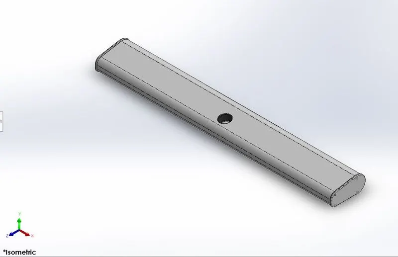
Marine radars are X band or S band radars on ships, used to detect other ships and land obstacles, to provide bearing and distance for collision avoidance and navigation at sea. They are electronic navigation instruments that use a rotating antenna to sweep a narrow beam of microwaves around the water surface surrounding the ship to the horizon, detecting targets by microwaves reflected from them, generating a picture of the ship's surroundings on a display screen. A Radar has a flat antenna that spins, emitting a signal, then listening back for that signal The return signal bounces back at varying times based on what it may be bouncing off.
it has a detection system that uses radio waves to determine the range, angle, or velocity of objects. It can be used to detect air crafts, ships, spacecrafts, guided missile, motor vehicles, weather formation, and Terrell. A radar system consists of a transmitter producing electromagnetic waves in the radio or microwaves domain, a transmitting antenna, a receiving antenna (often the same antenna is used for transmitting and receiving) and a receiver and processor to determine properties of the object(s). Radio waves (pulsed or continuous) from the transmitter reflect off the object and return to the receiver, giving information about the object's location and speed.
Features used to create Radar Mast
o Spline
o Extrude Bose
o Revolve
o Circle
o Mirror
o Line
o Mirror
o Fillet
o Chamfer
o shell
o projected curve
Methodology:
- Blue Print setup - Insert all views like Top view, Side view, bottom view, front view, etc.. by giving proper XYZ direction dimensions to it - Create two new planes Back Plane and Top Plane using Front & bottom plane as references.
- Insert the Super structure part by selecting the surface bodies. - Create a sketch on surface of radar mast by drawing a horizontal line at a distance of 160mm from surface and apply fillets outer and inner edges
- Draw 4 splines and a line as per Blue Print and extrude it on created plane - For Radar Indicators - Draw a sketch on Top face of Previous extrude using a line and 3 point arc., revolve it. Draw a circle on extruded face and extrude it. Apply fillets.
- For Antedate - Create a Sketch on Extrude face by drawing a circle and extrude it. Draw one more circle on extruded face and extrude it. Do one more extrude on previous extrude face by drawing a circle.
- Create a sweep by drawing a sketch on created plane using spline and a circle on 3D sketch.
- Mirror above sweep across Plane 2 and connect them by drawing three circle on sweep and extrude them.
- Create a Projected curve as per requirement by drawing sketches on respective Planes.
- Create a Sweep by drawing a circle at the edge of projected curve.
- For Horn -Draw few lines and splines as per blueprint do revolve. Apply Dome to one end and shell to other end
- Mirror Everything except Horn across Mid Plane
- For Ham Support- Draw a straight slot on Extrude 1 face and extrude unto Horn Face.
- Create a Plane using above extruded right face and offset it Mirror the Horn and its support across the created plane, - Finally give Appearance to Radar mast, Antenna, Horn & Indicators
- Rear Seat
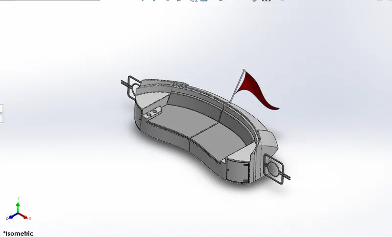
A seat is a place to sit. The term may encompass additional features, such as back, armrest, head restraint but also headquarters in a wider sense. It may also come under luxuries, materials use for the seat etc. here, this seat position on back side of the yacht. It is placed at the back end of the hull it can accommodate 3 persons and gives a perfect of the backside of the ocean, usually used for Altman watching. It is also designed with reference to the deck surface as the ground and the blueprint sketches as the reference for the dimensions and views.
Surface features are employed more in this seat than in the others. It is also provided with a flag at the end which is designed as a surface to represent the natural looks of a flag in wind. It lies at the back of the middle table and the end of the deck surface.
Features used to create Rear Seat:
o Surface loft
o Surface extrude
o Surface Offset
o Surface trim
o Sweep
o Ruled Surface
o Surface Extend
o Surface Knit
o Surface Extend
o Extrude Bose
o Chamfer
o Extrude Cut
o Mirror
o Plane
o Fillet
Methodology
- Blue Print setup - Insert all views like Top view, Side view, bottom view, front view, etc. by giving proper X, Y & Z direction dimensions to it. - Create two new planes Back Plane and Top Plane using Front & bottom plane as references.
- Insert the Hull part by selecting the surface bodies. - Mid Plane - Draw 2 Splines as per Blueprint dimension it to make full define.
- Create a Plane using Deck face & vertex of spline as references. - Create one more sketch on new plane by drawing a spline.
- Now using above two sketches do Surface Sweep.
- Create a offset surface of previous sketches by selecting respective faces. Trim the Extra Surface by drawing sketches accordingly.
- Use Ruled Surface to extend the surface and Knit everything. - Draw a sketch on Plane 1 using Splines which is used to trim surface.
- Create few Planes and draw sketches by causing convert entities and splines. Do Surface sweep using these sketches - Extend the Surface and trim the unwanted surfaces using surface trim and Knit them.
- Create few 3D Sketches and do surface loft.
- Create a sketch on deck face by converting respective entities and spline with midpoint, extrude it - For Hand resting - Create a Sketch on Previous Extruded face by selecting face and convert entities. Draw few lines as per blue print and trim extra entities, Extrude it.
- For Doors/Drawers - Create a cut extrude by drawing a lines on Front Plane,
- Offset the appropriate faces for creation of Seats in the surfaces by keeping the selection to split the surfaces.
- For Upper Seats - Create a Boss Extrude by drawing Sketch on offset surface using convert entities and line. Apply Chamfer and fillets accordingly.
- For Lights - Create a sketch on Plane 4 by drawings and extruding line. - For Locking Gates - Create few planes as per requirement and draw sketches accordingly using circle and line. Using these sketches sweep and mirror it.
- Mirror the Bodies across Mid Plane by Selecting Knit Surfaces & Merge solids. - Mirror seats and gates across Mid Plane separately by deselecting Knit Surfaces & Merge solids.
- For Flag Stand - Create a sketch on Mid Plane by drawing lines at an angle and revolve it.
-For Flag - Create four 3D Sketches by drawing spline with midpoints in each sketch and loft the surface.
-Finally Give Appearance to Seats, Lower Surface, Flag, Hand resting, Lights, Drawers & Gate.
- Middle Seat
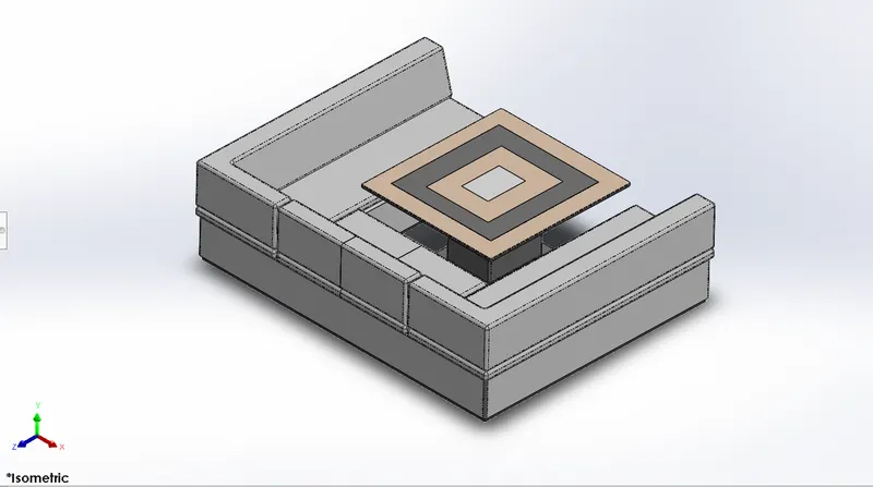
The middle seats are designed to accommodate more people. It can accommodate 6 people and a Table is provided at the centre to have a party. This is located between superstructure and the rear seat. A seat is a place to sit. The term may encompass additional features, such as back, armrest, head restraint but also headquarters in a wider sense it is also designed with reference to the deck surface as the ground and the blueprint sketches as the reference for the dimensions and views. This seat is U shaped seat with a table in the middle. It lies behind the superstructure of the Yacht. This part deign was done without involving surface design.It may also comes under luxuries, materials uses for the seat etc. here, this seat position on centre of the yacht.
Features used to create Middle Seat
o Extrude Bose
o Chamfer o Fillet
o Mirror
o line
o Rectangle
o Sketch
o Offset Entities
o Extrude Cut
Methodology
- Blue Print setup - Insert all views like Top view, Side view, bottom view, front view, etc.. by giving proper XY & Z direction dimensions to it.
- Create two new planes Back Plane and Top Plane using Front & bottom plane as references.
- Insert the Hull part by selecting the surface bodies.
- Draw a L Shape using lines on face of deck and extrude for lower portion of seat.
- Create a sketch on above extrude face offset the face and extrude. Create a Plane on above extrude face by offsetting at a distance of 5mm. Sketch on it by drawing lines as per blueprint and extrude.
- Mirror the bodies across Mid Plane by selecting Knit Surfaces and merging solids.
- Mirror seats across Mid Plane by DE-selecting Knit Surfaces and Merging solids. - Create a Table by selecting deck face using lines and offset entities.
- Create a Cut Extrude at the top surface of the table and apply fillets.
- Finally give Appearance to Table & Seats.
- Front Seat
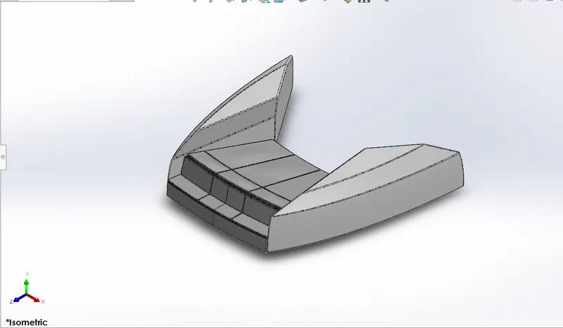
A seat is a place to sit. The term may encompass additional features, such as back, armrest, head restraint but also headquarters in a wider sense. it is designed with reference to the deck surface and the blueprints. It is designed using surface features and also extrude features. Domes are applied to the surfaces to imitate the cushions of the seat. A small water pool lies in the superstructure behind the front seat. It may also come under luxuries, materials use for the seat etc, here, this seat position on front side of the yacht. The front seat is designed on the front to have the perfect view of the ocean and can accommodate 2 people,
Features used to create Front Seat
o Plane
o Sweep
o Surface Loft
o Surface Trim
o Extrude Cut
o Revolve
o Surface Knit
o Surface Fill
o Dome
o Mirror
o Fillet
o Chamfer
Methodology
- Blue Print setup - Insert all views like Top view. Side view, bottom view, front view.etc. by giving proper XY & Z direction dimensions to it.
- Create two new planes Back Plane and Top Plane using Front & bottom plane as references.
- Create Swept Surface by creating a sketch on Deck face by drawing a spline & another sketch on created plane by drawing a line. - Draw two lines and connect with previously created surface sweep and Extrude the surface.
- Trim the Extra surface and fill the gap portion with Filled Surface.
- Draw few sketches accordingly to trim extra surfaces.
- Create Surface loft using above two sketches. Knit it together.
- Trim the Extra surfaces & Draw lines accordingly to create seat and revolve it about 10 degree.
- Apply Fillets and mirror the bodies.
- Finally Apply Dome to seats & give appearance.
- Radar Mast
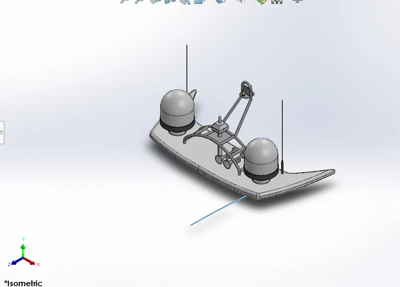
Marine radars are X band or S band radars on ships, used to detect other ships and land obstacles, to provide bearing and distance for collision avoidance and navigation at sea. They are electronic navigation instruments that use a rotating antenna to sweep a narrow beam of microwaves around the water surface surrounding the ship to the horizon, detecting targets by microwaves reflected from them, generating a picture of the ship's surroundings on a display screen A Radar has a flat antenna that spins, emitting a signal, then listening back for that signal The return signal bounces back at varying times based on what it be bouncing off. This is the part used for the GPS and navigation of the ship
Features used to Create Radar
o Sketch
o Extrude
o Fillet
o Line
o Polygon
o Circle
o Text
o Mirror
Methodology
- Right Plane - Draw a Trapezium using lines & extrude it.
- Sketch on Face of previous extrude by converting sketch 1 entities & extrude it.
- Sketch on Face of Sketch 1 extrude by drawing a circle at a distance of 60mm from lower edge converted entity & extrude
- Draw a circle on Previous Extrude face and do cut extrude.
- Use Sketch point to locate the previous extrude at required place and do sketch pattern.
- Now mirror across Right Plane.
- Draw a circle at lower edge of Radar face & do cut extrude.
- Sketch on Outer face of Radar using line, insert text as of choice and split across line.
- Finally give Appearance to it.
- Garage Door
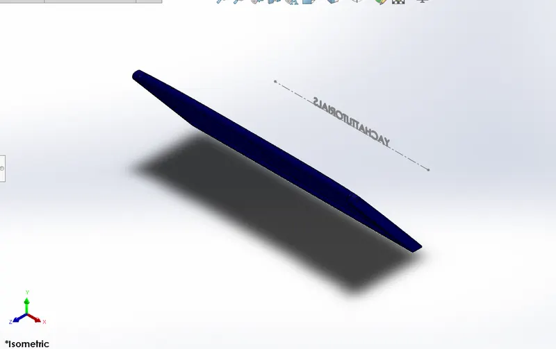
It's a door for the Garage. A garage door is a large door on a garage that opens either manually or by an electric motor (a garage door opener). Garage doors are frequently large enough to accommodate automobiles and other vehicles. Small garage doors may be made in a single panel that tilts up and back across the garage ceiling.it was created out of the split ed block from the Hull. It is provided with two holes to adjust the pins in order to open or close the garage door. It encloses the garage space which can accommodate a locomotive inside it.
Features used to Create Garage Door
o Extrude cut
o Mirror
o Text o fillet
o shell
o plane
Methodology
- Open Garage Door part which was saved while designing Hull part Create a sketch on right face of Stock by drawing lines and do cut extrude
- Apply Shell by selecting faces of the stock
- Draw a circle at the top by selecting side face of stock and do cut extrude to create a hole.
- Apply fillets & mirror across Right Plane.
- Create a plane using Front Plane as a reference by offsetting it. - Draw a sketch on created Plane by drawing Horizontal Center line and insert Text in Text box, do cut extrude.
- Finally give Appearance to Door and Text.
- Propeller
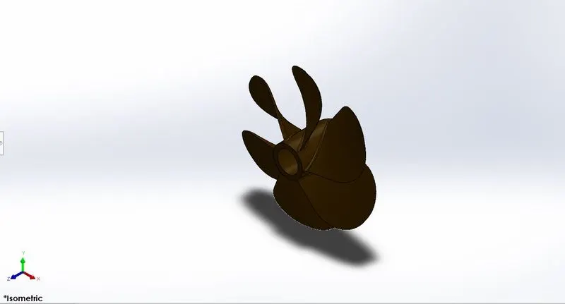
A Propeller is a device with a rotating hub and radiating blades that are set at a pitch to form a helical spiral, that when rotated, performs an action which is similar to Archimedes' screw. It transforms rotational power into linear thrust by acting upon a working fluid, such as water or air. The rotational motion of the blades is converted into thrust by creating a pressure difference between the two surfaces. A given mass of working fluid is accelerated in one direction and the craft moves in the opposite direction. Propeller dynamics, like those of aircraft wings, can be modelled by Bernoulli's principle and Newton's third law. Most marine propellers are screw propellers with helical blades rotating on a propeller shaft with an approximately horizontal axis. The sketch profiles are created with provided dimensions and the features are applied.
There are three instances of the propeller at the bottom of the yacht.
Features used to Create Propeller
o Sketch
o Line
o Circle
o Loft
o Rectangle
o Revolve
o Circular Pattern
o Fillet
o Extrude cut
Methodology
Right Plane - Draw 2 horizontal lines, 1 vertical line & a spline connecting left end points of horizontal lines and revolve it.
- Create a new plane, Top plane as reference at an offset of 360mm.
- Top Plane - Draw a 3-point rectangle at an angle of 74from bottom edge of revolve.
- New Plane - Draw one more 3-point rectangle at an angle of 14 degree from similar edge.
- Using above two sketches create a loft surface & apply fillet.
- Draw a circle on bottom face of revolve and do cut extrude, apply fillet.
- Do circular pattern of above above features in feature scope with 6 no. of instances.
- Give Appearance to the part of light red colour changing RGB values to 71/45/0.
- Assembly
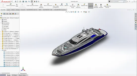
The assembly of the Yacht is quite simple since we have taken the base deck surface for the most of the parts it gets mated automatically although some mates are used to assemble the Yacht.
Mates Used
o Coincident
o Concentric
o Angle Limit
Steps to be followed for Assembly
- All Designed Parts to be inserted one by one as per requirement.
- Apply Mate Conditions with respective parts for giving exact location in Assembly.
- In this assembly Only Rear seat, Radar and Propeller are to located using coincident and Concentric relations with respective Parts. Other Parts are already fixed (Using Surfaces as references) so no need of giving separate mate conditions.
- Final Rendering:
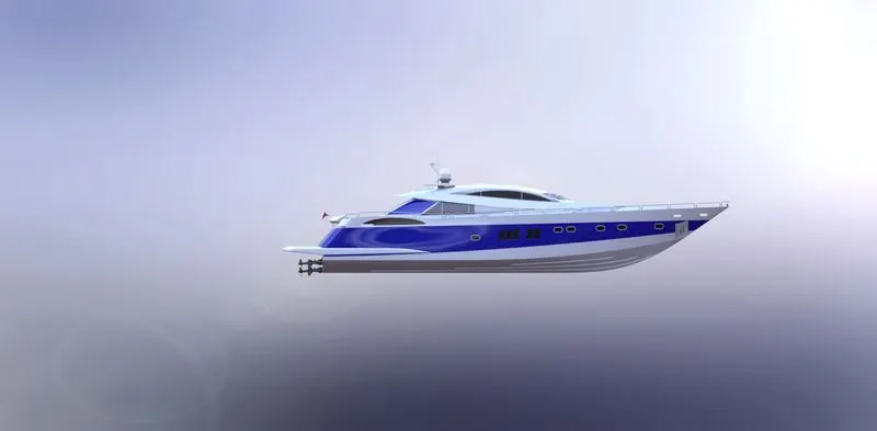
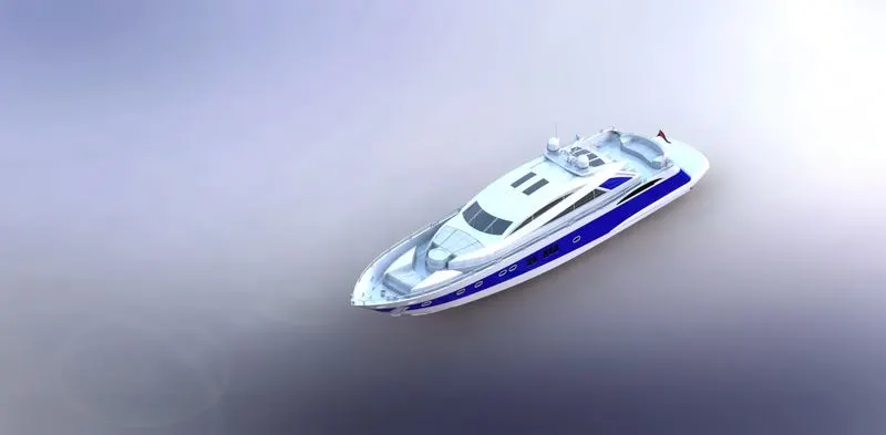
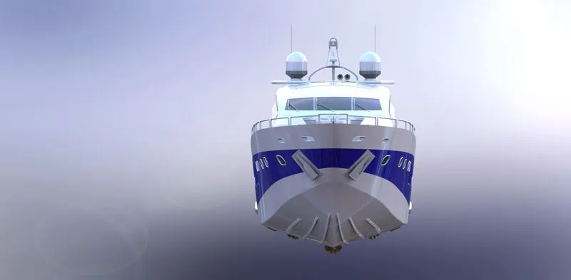
In this our Yacht Assembly rendered to make it more realistic using Solid-works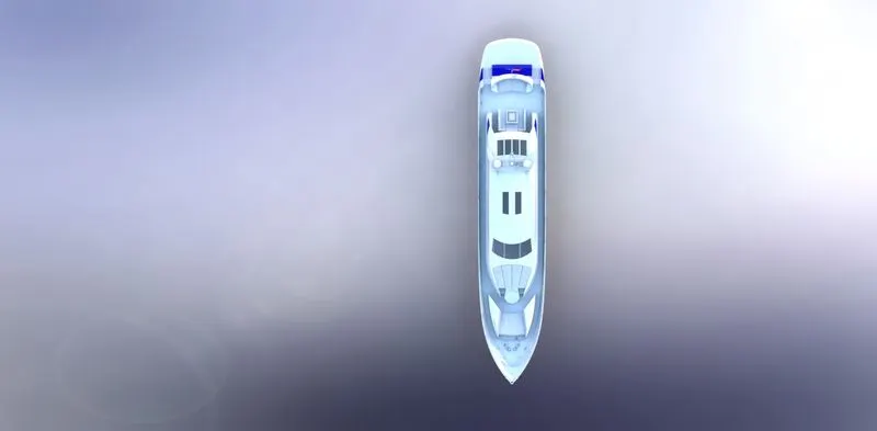
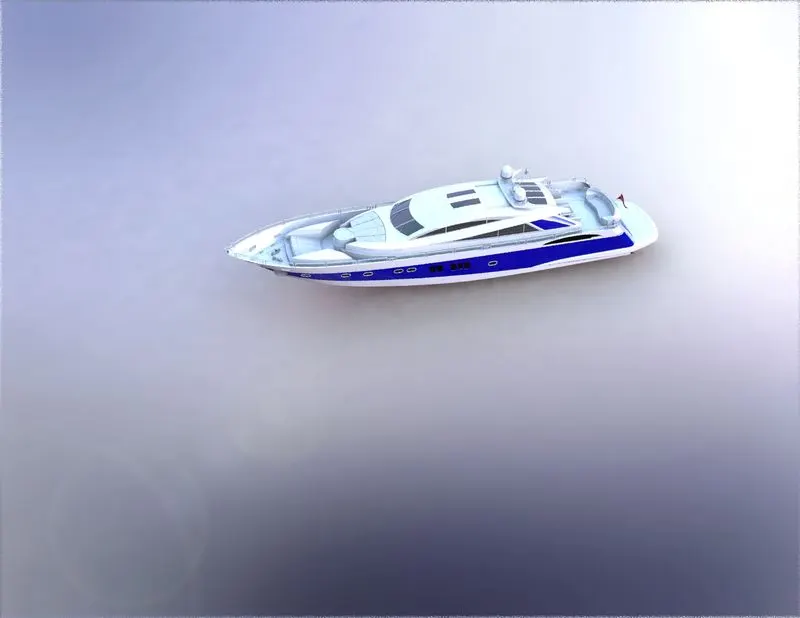
Methodology
o Import - Import assembly once created a new project.
o Appearance - Give appropriate appearances to various parts to make more attractive after rendering.
o Scenes - Use Proper Back Plates/Environment as scenes and drag the assembly at proper location.
o Decals: Graphics or designs used
o Lights & cameras. To adjust lighting and set camera
o Output - Once done with all setup, a quick render helps you out to review final output. Changes the colours by increasing/decreasing various values for better look (if required). Then go for final quality rendering
CONCLUSION
To conclude, design, assembly and rendering of the Sun seeker Predator Yacht are done using SOLIDWORKS.