Advanced Sheet Metal Design Using NX Cad Challenge_6_Bracket
TO DESIGN A SHEET METAL BRACKET BY USING SIEMENS NX CAD
Objective:
The main aim is to design sheet metal bracket by using NX CAD.
Introduction:
To design a bracket in sheet metal, brackets are used to support and holding the load like a fixture. Brackets need more strengthening to withhold the weight of the objects.
Wall mounted brackets are used for tv mount, door handles, etc.,
Design methodology:
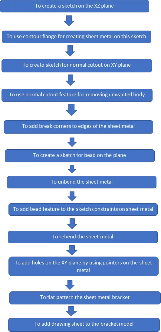
Features used for design a casing:
- Sketch
- Contour flange
- Create sketch for normal cutout
- Normal cutout
- Break corners
- Create sketch for bead
- Unbend the sheet metal
- Bead feature
- Rebend the sheet metal
- Holes
- Flat pattern the sheet metal
- Add drawing sheets to model
Sketch:
To setup the coordinate system and draw a sketch by giving dimensions and constraints to the plane, in this model to use origin point and make the sketch portion by using tools like
- Line
- Curve
For sketch by given dimensions for contour flange.
Contour Flange:
To add contour flanges to sketch model for required thickness and direction.
Sketch for normal cutout:
To create sketch constraints on the XY plane for normal cutout.
Normal cutout:
To add this feature for to remove the unwanted portion from the sheet metal.
Break corners:
To add this feature to transition the edges into smooth fillets by giving radius to the sheet metal.
Sketch for bead:
To add create sketch on the required plane for creating bead by giving the sketch constraints.
Unbend:
To unbend the model for further operations by selecting the center face for unbend the sheet metal.
Bead:
To create a bead on the sheet metal for providing addition strength to the model.
Rebend:
To rebend the model by selecting the feature and make select stationary face and drag the left mouse button on the model.
Create holes:
To create holes on the plane by giving sketch pointers and add diameter to them.
Flat pattern:
To flat pattern the model for drafting and manufacturing purpose.
Drafting:
To adding into drawings file for manufacturing the model by referring dimensions.
Bracket design tree:
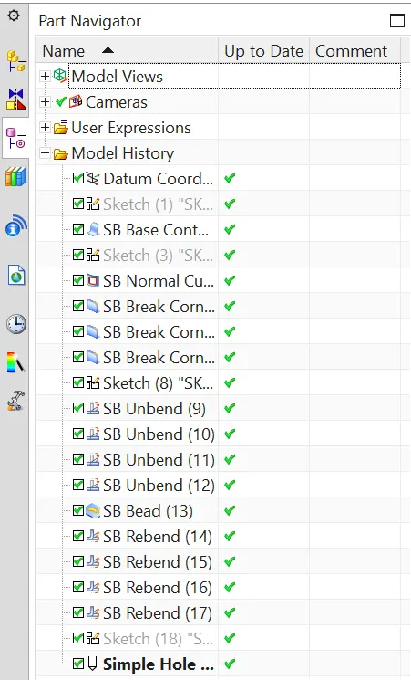
Tree image
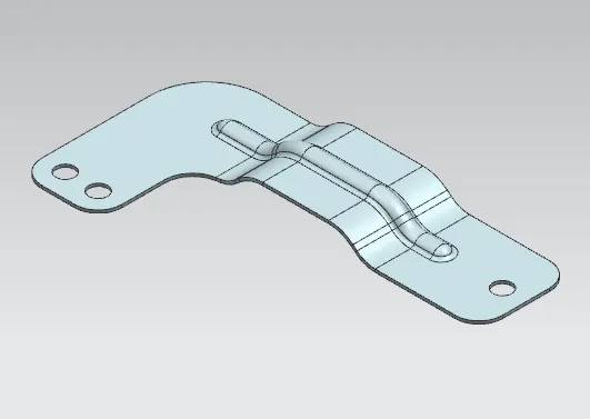
isometric view
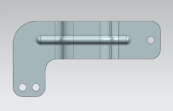
Top view
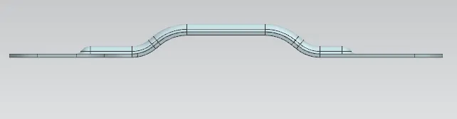
Front view
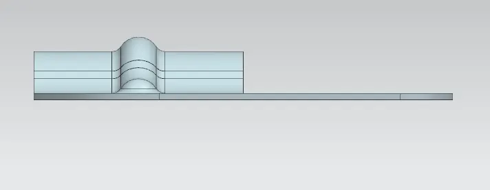
Side view
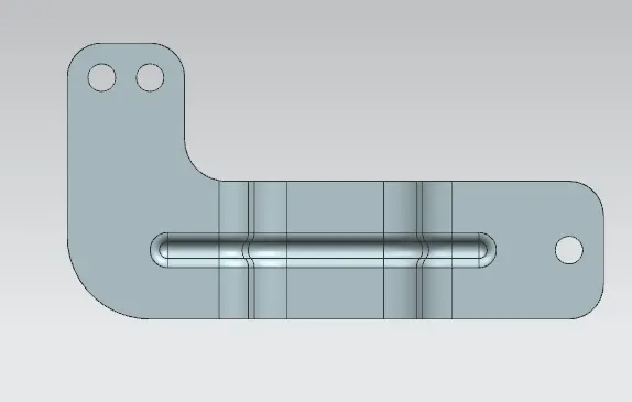
Bottom view
Drafting images:
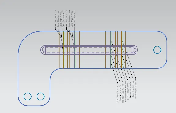
Flat pattern image
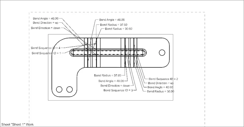
Flat pattern drawing
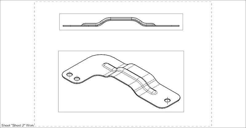
Front and isometric
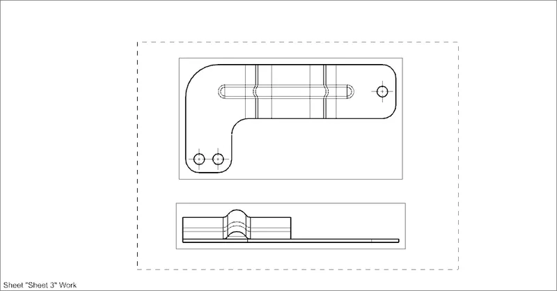
Top and right view
Conclusion:
To learn the sheet metal designing and tool methodology by design bracket in sheet metal by using tools and it’s features by using NX CAD.