Radar Mast & Final Assembly of Yacht
DESIGN, ASSEMBLY AND- PHOTOREALISTIC RENDERING OF AN AMERICAN PREDATOR YACHT
OBJECTIVE
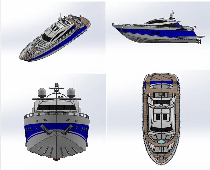
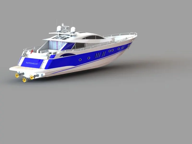
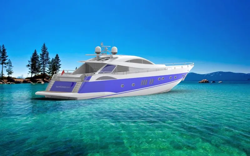
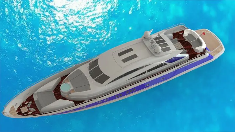
The objective of the project is to design and model all the parts of an American Predator Yacht and assembling it to create the Photo- Realistic rendering of the yacht.
INTRODUCTION
In this project the American Predator Yacht was taken as a conceptual model, to understand the 3D modelling methodology of Solid Modelling and Surface Modelling. Each and every part of the yacht was designed and modelled using SOLIDWORKS. Then the modelled parts were assembled by adding proper mates and constraints to create the Photo- Realistic rendered image of the Yacht.
SolidWorks is a solid modelling computer-aided design (CAD) and computer-aided engineering (CAE) computer program published by Dassault Systèmes, that runs primarily on Microsoft Windows. SolidWorks is a solid modeller to create models and assemblies.
Rendering of the assembly is done to make good quality 2D images for the purpose of advertising and promotion of the products before selling it to the customers. Photorealistic rendering creates high quality images or motion graphics if available so as to look appealing in various environments and backdrops.
SOLIDWORKS Visualize is a photo-realistic rendering tool that utilizes our CAD data to create magazine quality images or commercial quality animations.
DESIGN APPROACH
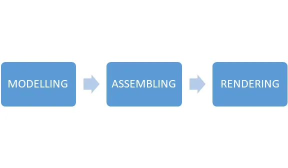
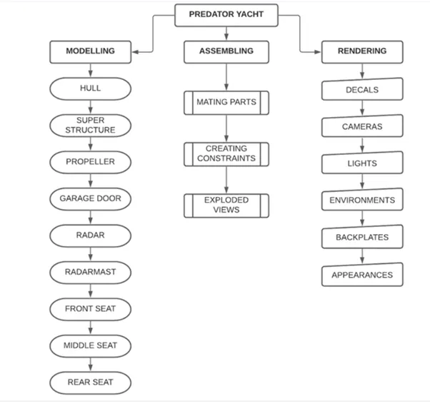
FEATURE COMMANDS
1.Extruded Boss/ Base:The Extruded Boss is the most basic of all SOLIDWORKS features and extrudes a sketch along a straight-line path to add material. As a sketched feature, it requires a sketch before use. Once the sketch has been created, exit the sketch and select the Features tab of the Command Manager. Then, click the Extruded Boss/Base command.
- Extruded Cut: Similar to the extrude boss feature this feature needs a sketch on the solid body which needs to be cut and the desired shape is then cut off.
- Split: Lines are used to divide model faces into two. Split lines are created like any other sketched feature. They can be one or more connected sketch entities. They must be oriented so that they will pass through model faces when projected normal to the sketch plane.
- Dome: It can add one or more domes to the selected planar or non- planar faces. The software calculates the distance using the radius of the arc as basis for the dome
- Pierce Relationships: The pierce relationship is used in sweeps. It can be thought of as a 3D coincident relationship. In our spring, the circle will follow the helix. Think of the helix as a thin piece of wire and the profile sketch a being drawn on a piece of paper. If we stick the wire through the paper at the center of the circle, this would be a pierce relationship. When we perform the sweep, the paper will slide along the wire, held at the pierce point.
- Project Curve: Select Bi- directional to create a projection that extends on both sides of the sketch. The curve can be used as a path for sweep
7.Composite Curve: We can create composite curves by combining curves, sketch geometry and model edges into a single curve. Composite curve can be used as a guide curve when creating a loft or a sweep
- Wire Frame: It is a view mode in which all edges of the part or assembly are displayed.
SURFACE MODELLING
Surface Modelling is a method of creating planar or non-planar complex geometry which has zero thickness. This zero thickness geometry is known as surface. We can convert surface models into solid models. We can also extract a surface from solid model using the tools available for surface modelling.
SURFACE COMMANDS
- Lofted Surface : Creates a lofted surface between two or more profiles or sketches. We should specify start and end constraints and add guide curves to control path shape.
- Boundary Surface : This feature lets to create surfaces that can be tangent or curvature continuous in both directions.
- Extruded Surface : Extrudes a selected sketch in one or two directions.
- Revolved Surface : Revolves a selected sketch around an axis.
- Swept Surfaces : It sweeps a closed profile along an open or closed path to create surface feature.
- Filled Surface : Patches a surface within a boundary defined by edges, sketches or curves.
- Ruled Surfaces : Inserts a ruled surfaces in a specified direction from edges. Tangent to surface, Normal to Surface, Tapered to vector, perpendicular to vector or sweep can be selected.
- Trim Surface : It trims the surface where a surface intersect with another surface, a plane or a sketch.
- Knit Surface : It combines two or more adjacent, non- intersecting surfaces into a single surface body. We can also create solid body.
- Move/ Copy Surfaces: Moves or copy surface about a plane or a sketch.
- Offset surface : Helps to create an surface with gaps.
- Extend Surface : Extends one or more edges or faces on a surface based on end conditions and extension type.
- Mirror Surfaces : It is a copy of a selected feature, mirrored about a plane or face. If the original sketch is changed, mirrored copy also updated automatically.
- Reference Plane : We can create planes in part or assembly document.
- Fillet : It is an internal rounding of a corner or edge in a sketch
- Split Line : It divides selected face into multiple separate faces.
PART MODELLING DESCRIPTION
1.BLUEPRINT
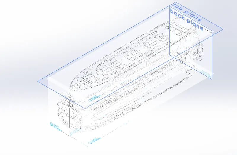
A blueprint is a reproduction of engineering drawing using contact print process on light sensitive sheets. Blueprint is a guide for making something.
2. HULL
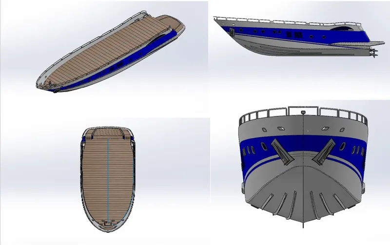
A hull is the watertight body of a ship, boat, or flying boat. The hull may open at the top , or it may be fully or partially covered with a deck. The line where the hull meets the water surface is called the waterline.
Tools used
Sketch Tools:
- Line
- Spline
- Rectangle
- Arc
- 3D sketch
- Straight slot
Surface Tools:
- Extruded Surface
- Revolved surface
- Lofted surface
- Surface trim
- Surface fill
- Surface Knit
Feature Tools:
- Dome
- Fillet
- Projected Curve
- Mirror
- Extruded Cut
- Extruded Boss
Modelling Procedure
- Creating a blueprint
- By using this hull was designed
- Shape of the hull is obtained using projected curve produced by drawing splines with the help of blueprint.
- Then the curves were lofted to create a lofted surface and remaining unwanted portion is trimmed.
- Back portion of the hull where the propeller needs to be placed was extruded using extruded surface and all surfaces knitted together with gap tolerance 0.1 mm.
- Then the offset option is applied and another surface created and both surface filled using surface fill.
- Shell feature was used to create the front portion where deck surface meets.
- Then the required chamfers and fillets were added.
- Windows and portholes were created using extruded cut and fillet is applied.
- A 3D sketch is created around the window hole to make a smooth edge using pierce and swept feature.
- Rails were created at the bottom of the yacht using extruded boss and fillets and chamfers added.
- The cable rollers were created using extruded boss and swept base and head part of it was created using revolved boss and extruded cut and dome created over it.
- Railings around the hull was generated with the help of blueprint and hand supported bar is created.
- Rope around the cable rollers created using spiral sketch and sweep.
- Staircase were created using extruded boss.
- By using straight slot option rope hangers were extruded and dome was applied.
- The axles for the propeller and surfer were created using revolved boss using 3D sketch. And linear pattern is applied.
- The half part of anchors were created and mirrored.
- Finally garage portion was created using extruded cut and portion saved separately using split option.
- Appearances applied to each part of hull and mirrored whole body about mid plane.
- Save the part.
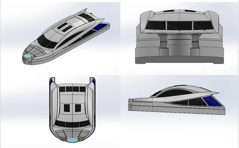
3.SUPERSTRUCTURE
A superstructure is an upward extension of an existing structure above a baseline. The size of the superstructure has a great influence on the mobility of the vessels. They are designed in a manner, so that, they add value and hinder the speed and mobility in the least. The superstructure is mostly designed in fashion as well.
Tools Used
Sketch Tools:
- Line
- Spline
- Circle
- Rectangle 3D sketch
Surface tools:
- Extruded surface
- Swept surface
- Knit surface
- Extend surface
- Filled surface
- Fillet
- Chamfer
- Revolved surface
- Lofted Surface
Feature Tools:
- Project Curve
- Split Line
- Reference Plane
- Convert entities
Modelling Procedure
- Deck surface from hull is imported and superstructure was modelled over it.
- Side surface of the superstructure was created using extruded surface, lofted surface, fill surface and knit options.
- Front side of the superstructure was designed with four rest beds using extruded boss, fillet and dome features.
- Front edge provided with water feature.
- The wind shield was created by extruded cut and wipers were created using 3D sketch.
- The portholes were created using extruded surface, trim surface and extend surface.
- Ruled surface was used to fill left out edges.
- All surface were knitted with 0.1 mm gap tolerance to create a solid body.
- The backdoors were created using extruded cut and fillets.
- All surfaces were mirrored about mid plane.
- Top surface of superstructure is offset with 0mm clearance for reference of radar mast.
- Appearance added for all bodies and part saved.
3.PROPELLER
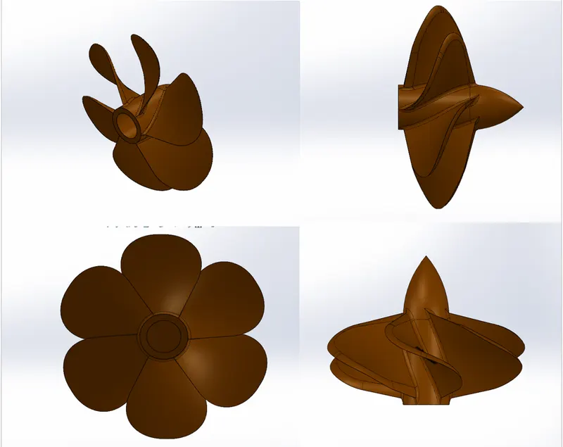
A propeller is a device with a rotating hub and radiating blades that are set at a pitch to form a helical spiral, that, when rotated, exerts linear thrust upon a working fluid, such as water. Yacht consists of three propellers. It’s working principle is Newton’s third law of motion.
Tools Used
Sketch tools:
- Spline
- Circle
- Line
Feature Tools:
- Revolved Boss
- Extruded Cut
- Fillet
- Circular Pattern
Modelling Procedure
- Hub was created using revolved boss and a hole was created at the centre using extruded cut.
- One blade is created using lofted surface and fillet and creates a circular pattern around hub for other blades.
- Proper appearance added and part saved.
4.GARAGE DOOR
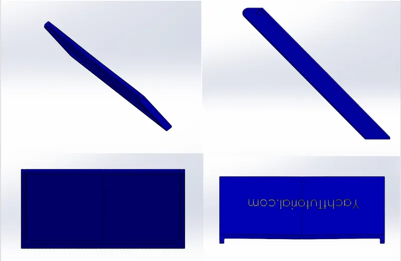
A garage door is a large door on a garage that opens either manually or by an electric motor. Garage doors are frequently large enough to accommodate auomobiles and other vehicles. Small garage doors may be made in a single panel that tilts up and back across the garage ceiling.
Tools Used
Sketch Tools:
- Line
- Spline
- Circle
- Text
Feature Tools:
- Extruded Cut
- Reference plane
- Fillet
- Shell
- Mirror
Modelling Procedure
- The solid body split while creating the hull was imported to model garage door.
- Chamfered face for the door was created using extruded cut.
- Solid body for garage door was created using shell feature.
- Door holders are created using extruded cut.
- The text made over the garage door.
- Proper appearance added and part saved.
5.RADAR
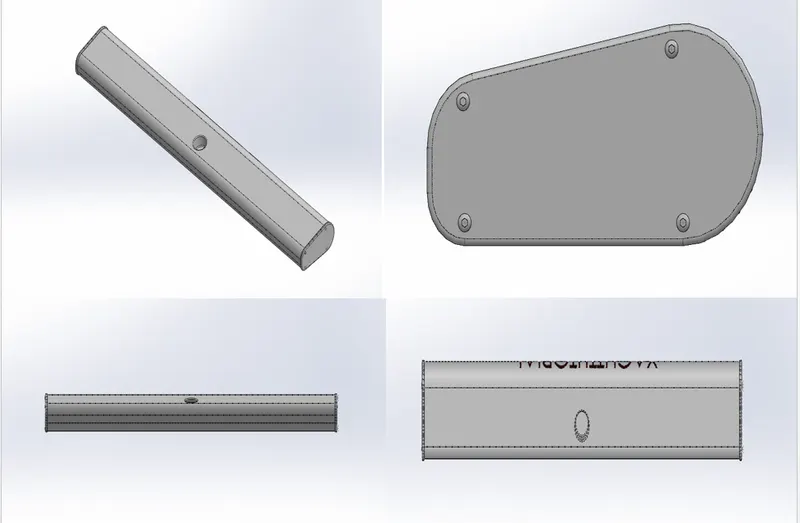
Radars are X band or S band radars on ships, used to detect other ships and land obstacles, to provide bearing and distance for collision avoidance and navigation at sea. They are electronic navigation instruments that use a rotating antenna to sweep a narrow beam of microwaVES around the water surface surrounding the ship to the horizon, detecting targets by microwaves reflected from them, generating a picture of the ship's surroundings on a display screen.
Tools Used
Sketch Tools:
- Line
- Text
- Circle
- Point
Feature Tools:
- Extruded Boss
- Extruded Cut
- Fillet
- Mirror
- Split Line
Modelling Procedure
- Body sketch was drawn and extruded.
- By using sketch pattern foyr dotted holes were created using extruded boss and extruded cut.
- A circular hole created under the radar using extruded cut.
- Mirrored next half of radar.
- Text made on the radar and appearance is added.
- Part saved.
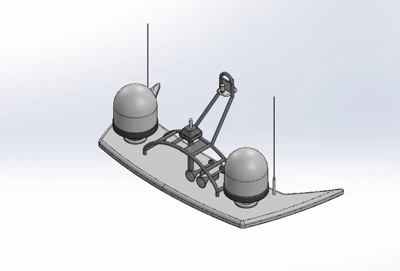
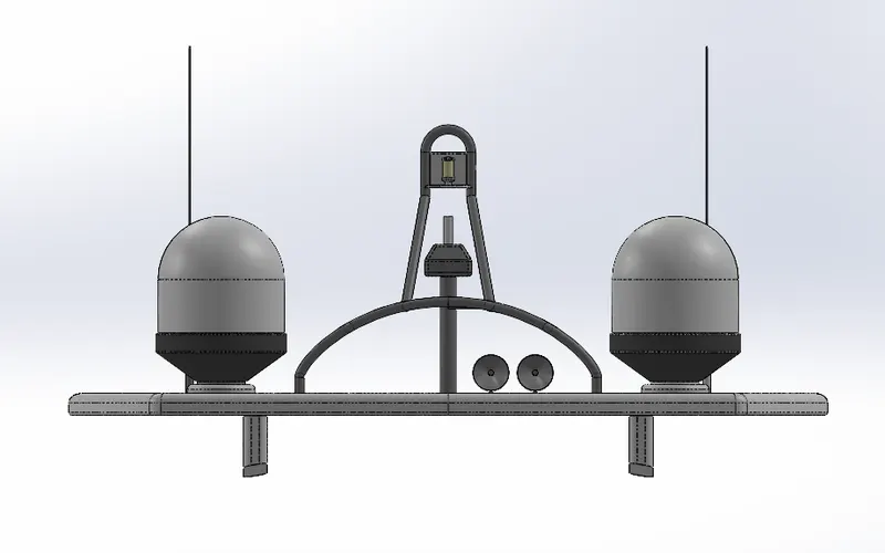
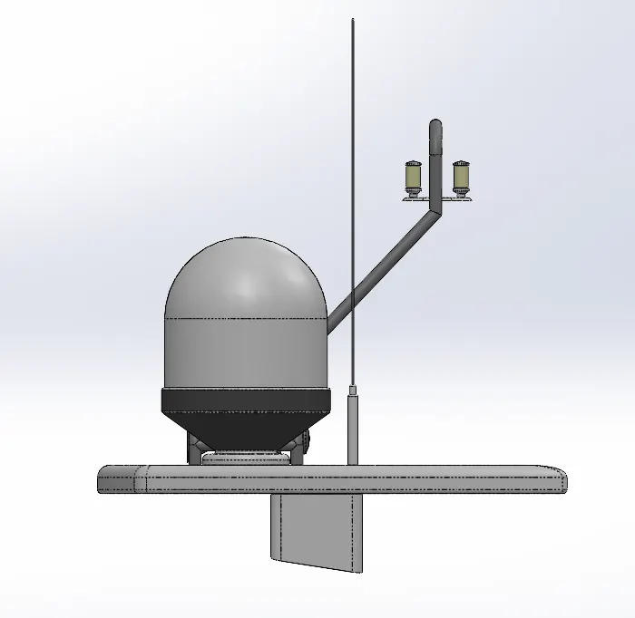
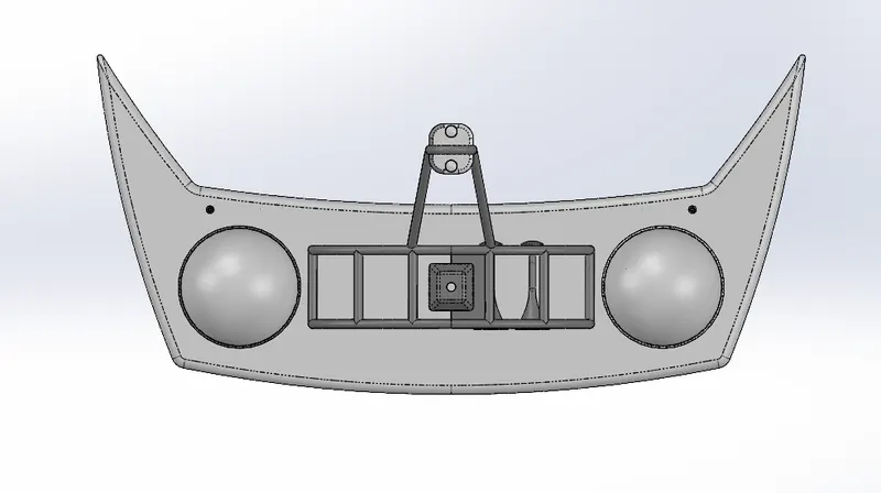
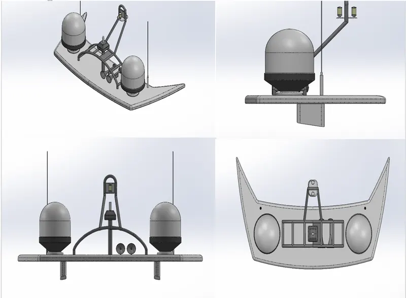
6.RADARMAST
The mast of a ship is a tall spar, or arrangement of spars, erected more or less vertically on the centre-line of a ship or boat.Its purpose to give necessary height to a navigation light, look out position, signal yard, control posstion, radio aerial or signal lamp.
Tools Used
Sketch Tools:
- Line
- Spline
- Rectangle
- Arc
- Sketch Picture
Feature Tools:
- Extruded Boss
- Revolved Boss
- Swept Boss
- Lofted Boss
- Reference Plane
- Dome
- Fillet
- Mirror
- Projected Curve
Modelling Procedure
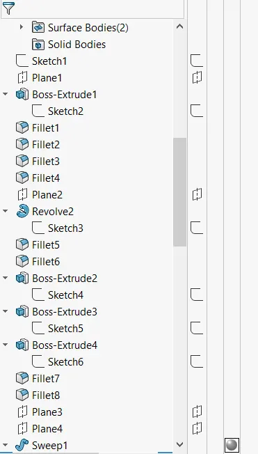
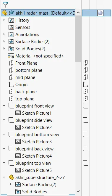
- The fisrt half of radarmast was created using blueprint and next half is mirrored.
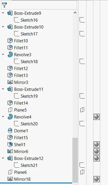
- Body of the radar mast created using extruded boss and revolved boss.
- Antenna for rad also created using extruded boss.
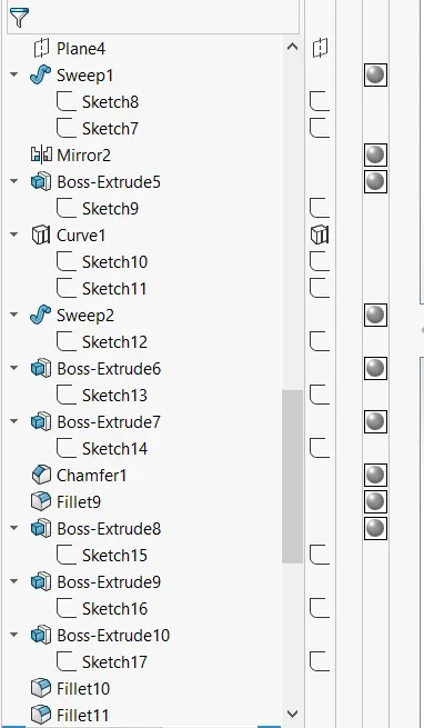
- Lamp stand along with connecting rod were created using swept boss.
- Lamp is created using swept boss and projected curve
- Horns were created using shept boss and shell.
- fillets added and apperanaces wre provied.
- Saved the part
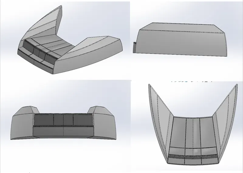
7.FRONT SEAT
Two connected seats that are built back-to-back from one and other. They have a built in storage unit underneath them.It is placed in front of the superstructure and it has sun pads to rest on them.
Tools Used
Sketch Tools:
- Sketch picture
- line
- Spline
- Arc
- Circle
Feature Tools:
- Extruded Cut
- Revolved Base
- Dome
- Fillet
- Chamfer
- Mirror
Surface Tools:
- Extruded Surface
- Loft Surface
- Trim Surface
- Fill Surface
- Knit Surface
- Swept Surface
Modelling Procedure
- Front seat created with the help of blueprint.
- The first half created and next haf mirrored.
- Body of front seat created using swept surface, extrude surface, loft surface and knit surface options.
- The chamfers, fillets and dom features added.
- Proper appearances added and part saved.
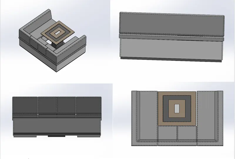
8.MIDDLE SEAT
Middle seats are just behind the superstructure. It provided with luxury table . It can also be used for casual meetings with copassengers.
Tools Used
Sketch Tools:
- Sketch Picture
- Line
- Rectangle
Feature Tools:
- Extruded Boss
- Fillet
- Chamfer
- Mirror
- Reference Plane
Modelling Procedure
- It is created using extruded boss and proper fillets and chamfers were added.
- All the surfaces created were knitted together with 0.1 mm gap clearance.
- Dining table created using reference plane and extruded base.
- Second part of the middle seat is mirrored about the mid plane.
- Proper appearances added and part saved.
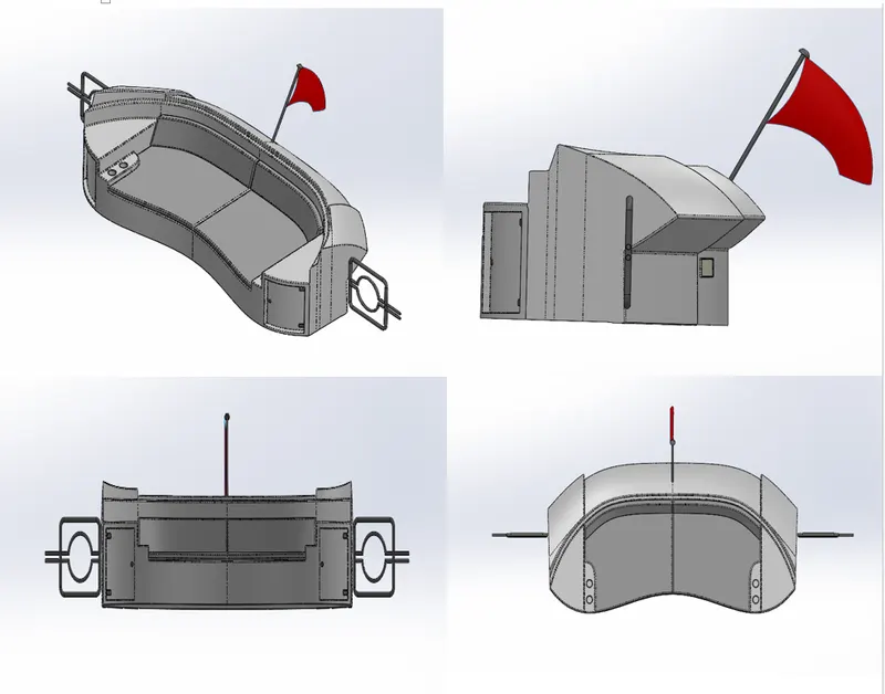
9.REAR SEAT
Rear seat was placed at the end of the deck surface. The rear seat consist of locker racks and steel doors for our stairs.The flag is placed behind the rear seat.
Tools Used
Sketch Tools:
- line
- Spline
- Arc
- Circle
- Rectangle
- Sketch Picture
Feature Tools:
- Reference Plane
- Extruded Boss/ Base
- Revolved Base
- Mirror
- Fillet
Surafce Tools:
- Swept Surface
- Extruded Surface
- Offset Surface
- Filled Surface
- Knit Surface
- Ruled Surface
- Lofted Surface
Modelling Procedure
- Main body is modelled using swept surface, offset surface and extra unwanted portions were trimmed off.
- By using reference planes seats were created with the help of lofted surface.
- Flag post was created using revolved boss and flag is created using 3D sketch.
- The tail lamps were created using Extruded boss.
- The steel gates for stairs were designed by using reference plane and swept surface.
- All the surfaces were knitted with 0.1 mm gap tolerance.
- The required fillets and chamfer were createdbefore mirroring
- mirror the next half part of rear seat.
- Finally appearances provied and saved the part
ASSEMBLY
An assembly is a document in which parts, features and other sub assemblies mated together.
Approach: Bottom- Up
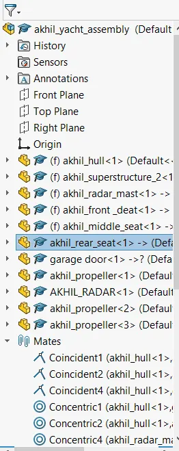
Bottom- Up design is the traditional method. You will first design and model the part individually, then insert them into an assembly and use mates to position parts. To change parts you must edit them individually. These changes are then seen in assembly. If there is any interference in the assembly or changes required in the assembly you need to modify the components individually either in the assembly level or in the part document level.
Assembly Commands
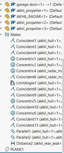
- Smart Mate: In this matring relation created automatically.
- Mate: A mate is a geometric relationship such as coincident, perpendicular, tangent and so on.
- Mate group: It is a collection of mates that are solved together.
- Sub assembly: It is an assembly document that is a part of a larger assembly.
- Insert Components: We can insert multiple group of components without closing the property manager.
Assembly Procedure:
- Insert each part manually using insert component option.
- Mate the planes of the hull with planes of the assembly by making coincident mate .
- Then for each part apply the necessary mates
- For garage door apply limit angle mate for door opening.
- Use offset mate of 50mm for rear seat.
RENDERING
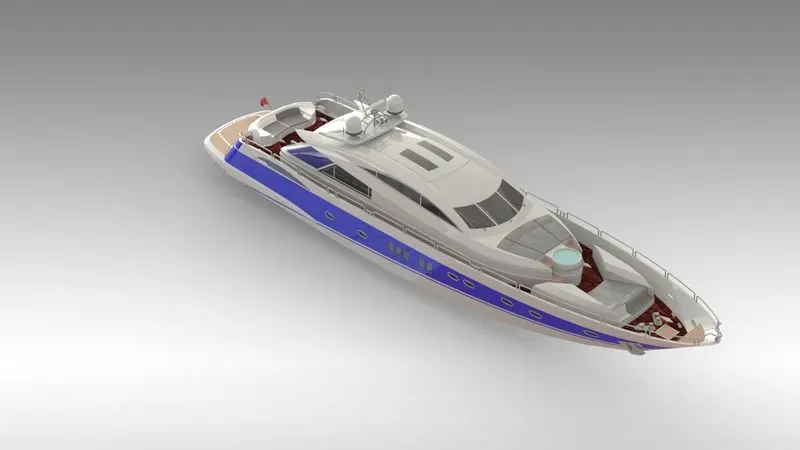
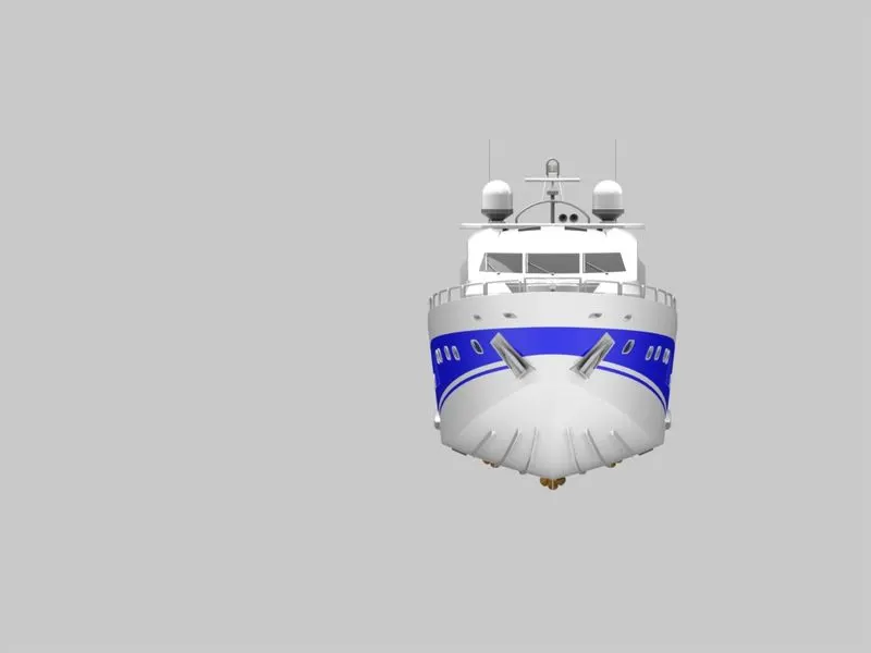
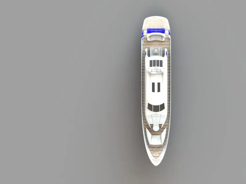
Rendering of the assembly is done to make good quality 2D images for the purpose of advertising and promotion of the products before selling it to the customers. Photorealistic rendering creates high quality images or motion graphics if available so as to look appealing in various environments and backdrops.
Photoview 360 is a visualization and rendering solustions included in solidworks.It provides highly interactive environments, lights, scenes,apperances decals and so on.
SOLIDWORKS VISUALIZE
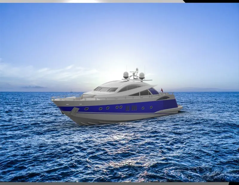
SOLIDWORKS Visualize allows create photo-quality content in the fastest and easiest way you can–from images to animations, interactive web content, and immersive Virtual Reality.It provides industry-leading rendering capabilities.Visualize produces only 2D rendered images, but has full access to the online libraries and all of the technology and tools to create beautiful renderings.
Rendered Samples
CONCLUSION
The project design,assembly and photo-realistic rendering of an AMerican Predator Yacht was modelled and rendered successfully.