Photo Realistic Rendering
MODELLING OF AMERICAN CHOPPER MOTORCYCLE USING SOLIDWORKS
OBJECTIVE
The objective of this project is to Supercharge design skills, discover how to sketch, model and render an incredible chopper. In the design, different sketch tools, defining relations to make the model fully defined, in assembly stage importance of mates and usage of photoview 360 as well as Solidworks Visualize completely understood.
INTRODUCTION
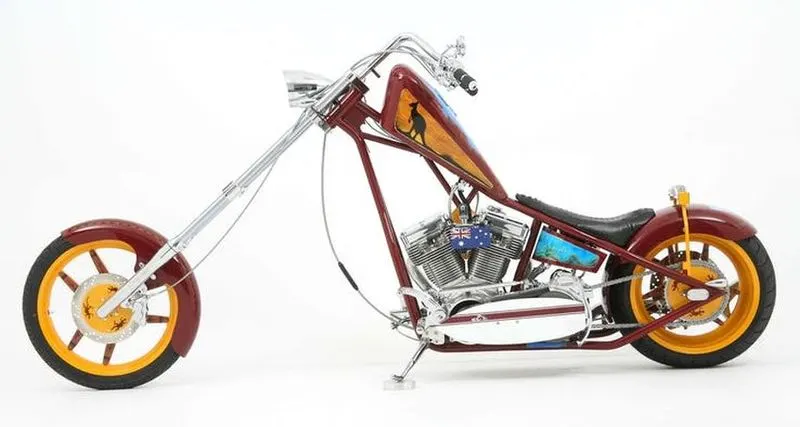
A chopper is a type of custom motorcycle which emerged in California in the late 1950s. A chopper employs radically modified steering angles and lengthened forks for a stretched-out appearance. Some of the characteristic features of choppers are long front ends with extended forks often coupled with an increased rake angle, hardtail frames (frames without rear suspension), very tall "ape hanger" or very short "drag" handlebars, lengthened or stretched frames, and larger than stock front wheels.
Design Tool: SOLIDWORKS
SolidWorks is a solid modelling computer aided design (CAD) and computer aided engineering(CAE) computer program published by Dassault Systèmes, that runs primarily on Microsoft Windows. According to the publisher, over two million engineers and designers at more than 165,000 companies were using SolidWorks as of 2013. Its user base ranges from individuals to large corporations, and covers a very wide cross-section of manufacturing market segments.
SolidWorks is a solid modeller, and utilizes a parametric feature based approach which was initially developed by PTC (Creo/Pro-Engineer) to create models and assemblies.
Parameters refer to constraints whose values determine the shape or geometry of the model or assembly. Parameters can be either numeric parameters, such as line lengths or circle diameters, or geometric parameters, such as tangent, parallel, concentric, horizontal or vertical, etc.
Features refer to the building blocks of the part. They are the shapes and operations that construct the part. Shape-based features typically begin with a 2D or 3D sketch of shapes such as bosses, holes, slots, etc. This shape is then extruded to add or cut to remove material from the part. Operation-based features are not sketch-based, and include features such as fillets, chamfers, shells, applying draft to the faces of a part, etc.
Building a model in SolidWorks usually starts with a 2D sketch. The sketch consists of geometry such as points, lines, arcs, conics (except the hyperbola), and splines. Dimensions are added to the sketch to define the size and location of the geometry. Relations are used to define attributes such as tangency, parallelism, perpendicularity, and concentricity. In an assembly, the analogue to sketch relations are mates. Just as sketch relations define conditions such as tangency, parallelism, and concentricity with respect to sketch geometry, assembly mates define equivalent relations with respect to the individual parts or components, allowing the easy construction of assemblies. Finally, drawings can be created either from parts or assemblies. Views are automatically generated from the solid model, and notes, dimensions and tolerances can then be easily added to the drawing as needed. The drawing module includes most paper sizes and standards
File formats in Soildworks
Parts : SLDPRT
Assembly: SLDASM
Drawing : SLDDRW
MODELLING AND ASSEMBLING FEATURES
Approach: Bottom- Up
Bottom- Up design is the traditional method. You will first design and model the part individually, then insert them into an assembly and use mates to position parts. To change parts you must edit them individually. These changes are then seen in assembly. If there is any interference in the assembly or changes required in the assembly you need to modify the components individually either in the assembly level or in the part document level.
1.Extrude Boss
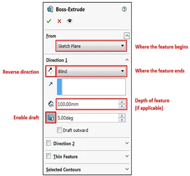
The Extruded Boss is the most basic of all SOLIDWORKS features and extrudes a sketch along a straight-line path to add material. As a sketched feature, it requires a sketch before use. Once the sketch has been created, exit the sketch and select the Features tab of the Command Manager. Then, click the Extruded Boss/Base command. If a yellow dialog box appears in the Property Manager asking you to create a new sketch, don’t worry – simply click on the sketch in the graphics area to use it for the feature. The Property Manager for the Extruded Boss allows you to control starting location, extrude depth and draft for the feature, among several other parameters:
2. Fillet
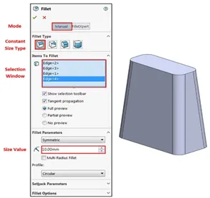
Fillets are classified as applied features, and as such do not require a sketch to be used. Fillets serve to round off edges and/or corners by adding or removing material, depending on whether the edge is internal or external. It should be noted that fillets of different sizes must be created as separate features. Typically, it is best practice to create the largest fillets first and follow with smaller fillets.
3. Revolved Boss Feature
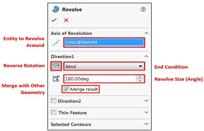
Adds material by revolving a sketch around an axis. Remember, once geometry has been created in your model, any flat face can be used as a sketching surface. It is very important to draw an axis in the sketch which needs to be revolved.
4. Extrude Cut
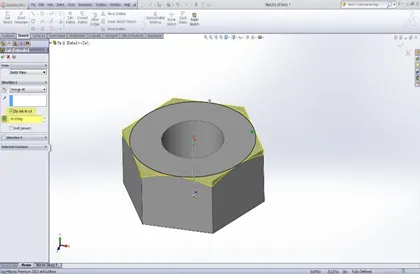
Similar to the extrude boss feature this feature needs a sketch on the solid body which needs to be cut and the desired shape is then cut off.
5. Shell
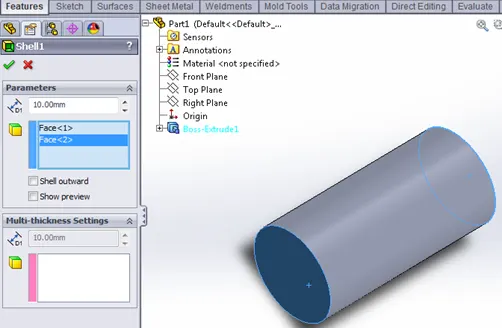
SolidWorks shell tool is mainly used for shelling process, in which the material removed from the inner body of model by keeping small thickness and results a hollow model. Using this tool, you can make either completely closed hollowed model or one face opened type.
6. Sweep Boss / Sweep Cut
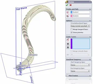
Sweep creates a base, boss, cut, or surface by moving a profile (section) along a path, according to these rules: The profile must be closed for a base or boss sweep feature; the profile may be open or closed for a surface sweep feature.
7. Loft Boss/ Loft Cut
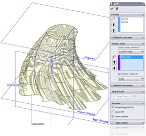
The loft feature is an important tool for (surface) modelling in SolidWorks. The loft feature creates a shape by making transitions between multiple profiles and guide curves. This tool is very valuable for modelling complex surfaces. You can do some cool stuff when you use this feature properly.
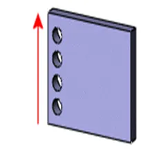
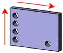
8. Linear Pattern:
You can use linear patterns to create multiple instances of one or more features that you can space uniformly along one or two linear paths. Pattern instances inherit the visual properties of the original feature when you select Propagate Visual Properties in the Property Manager.
9. Mirror
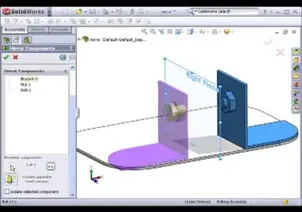
Creates a copy of a feature, (or multiple features), mirrored about a face or a plane. You can select the feature, or you can select the faces that comprise the feature. Bodies to Mirror: Select a body in a single model or multibody part to create a mirror entity. Multibody parts: Apply features to one or more multibody parts by selecting Geometry Pattern and using Feature Scope to choose which bodies should include the feature.
10. Reference Geometry
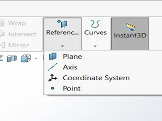
Reference geometry defines the shape or form of a surface or a solid. Reference geometry includes items such as planes, axes, coordinate systems, and points. You can use reference geometry in the creation of several kinds of features. For example:
- Planes are used in lofts and sweeps.
- An axis is used in a circular pattern.
11. Projected Curve
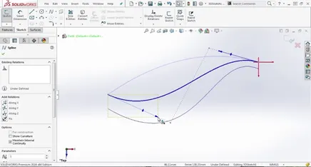
You can project a sketched curve onto a model face to create a 3D curve. You can also create a 3D curve that represents the intersection of two extruded surfaces generated by creating sketches on two intersecting planes. You can create multiple closed or open-contour projected curves from a single sketch. You can also use 3D sketches as input for the Projected Curve tool. Note: the Projected Curve tool does not support projections of intersecting curves.
12. Mate
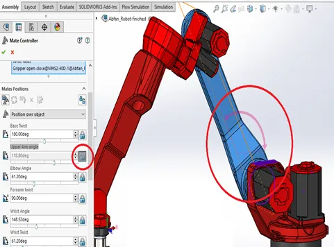
Mates create geometric relationships between assembly components. As you add mates, you define the allowable directions of linear or rotational motion of the components. You can move a component within its degrees of freedom, visualizing the assembly's behaviour.
Some examples include:
- A coincident mate forces two planar faces to become coplanar. The faces can move along one another but cannot be pulled apart.
- A concentric mate forces two cylindrical faces to become concentric. The faces can move along the common axis but cannot be moved away from this axis.
Mates are solved together as a system. The order in which you add mates does not matter; all mates are solved at the same time. You can suppress mates just as you can suppress features.
DESIGN METHODOLOGY
1. TRANSMISSION BELT
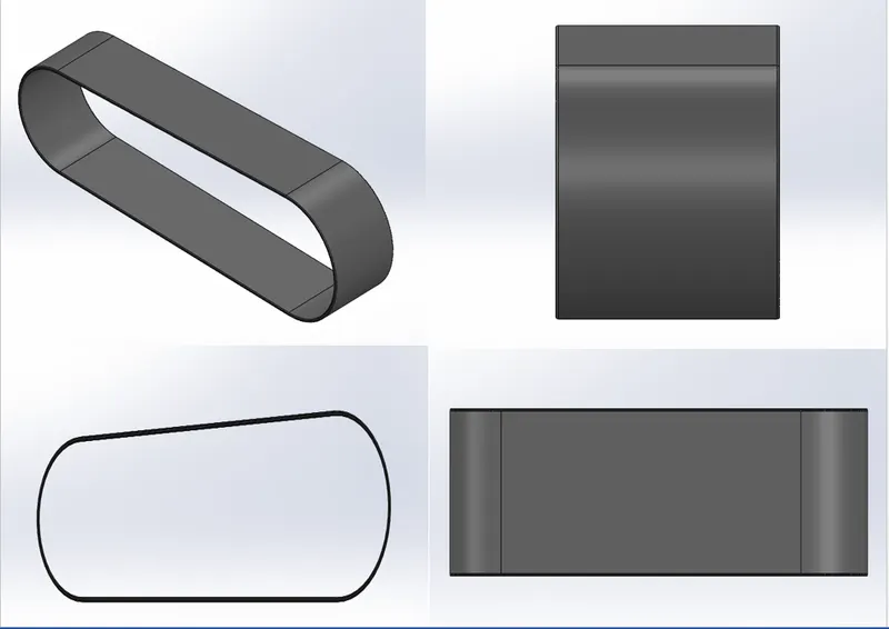
Transmission belt is a machine member used to transmit power from one pulley to another. Belts are commonly made of Rubber canvas material because of low slip, long life and low maintenance cost etc.
all views of transmission belt:
Tools Used
Sketch Tools:
- 3 point Arc
- Line
- Sketch Offset
Features:
- Extrude
- Fillet
- Appearance
2. KICKSTAND
all views of kickstand:
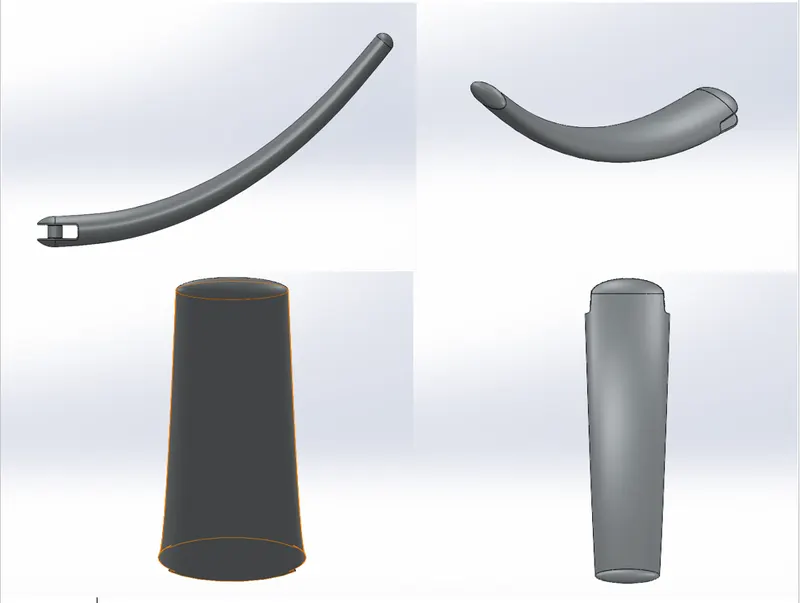
Kickstand is a machine member used to support the motorcycle in rest position. Kickstand is mounted to the chassis through a mounting point. While designing the kickstand we used the sketch drawing based on an additional plane, the sketch was used to create a lofted part and the dome features were applied on both the ends, then we used another sketch to flatten the surface which would rest on the ground to achieve the geometry, we also created an extrude cut for the assembly purposes. An extruded cylindrical boss is created join the cut parts and fillet is applied to the edges of the cut and joints of the boss. It is a metal chrome part.
Tools Used
Sketch Tools:
- Ellipse
- pierce
- Spline
Features:
- Loft
- Split
- Dome
- Extruded Boss
- Extruded Cut
- Fillet
- Appearance
3. FRONT FENDER
all views of front fender:
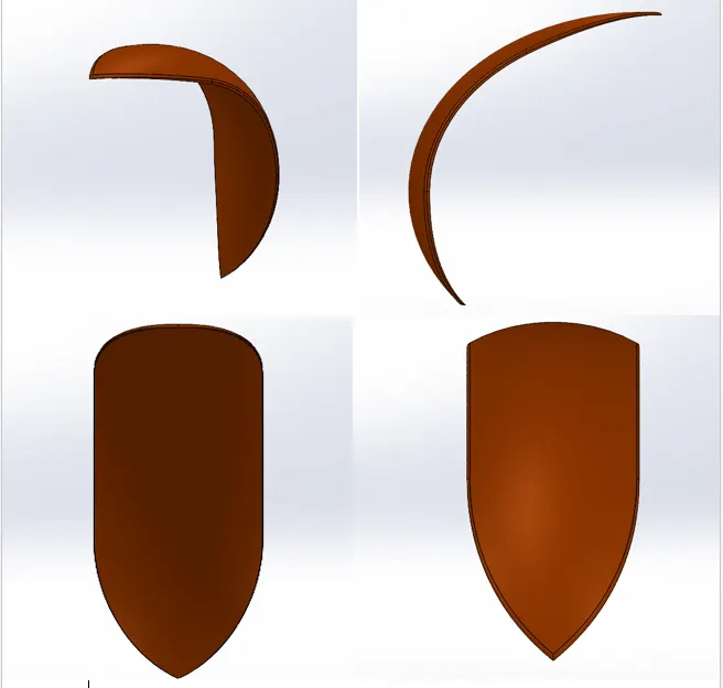
A fender is an automobile part that is bound to the vehicle frame and is placed as cover on the upper side of the tyres. Its primary purpose is to prevent sand, mud and other road spray from being thrown into the air by rotating tyre. This part is also known as mud guard. Here we have revolved the sketch using the axis again is a single solid body where both the sides have been designed with the help of sketches and the split tool. The outer edges of the fender are filleted.
Tools Used
Sketch Tools:
- 3 Point Arc
- Sketch Offset
- Line
- Spline
Features:
- Revolve
- Split
- Dynamic Mirror Entity
- Fillet
- Appearance
4. OIL TANK
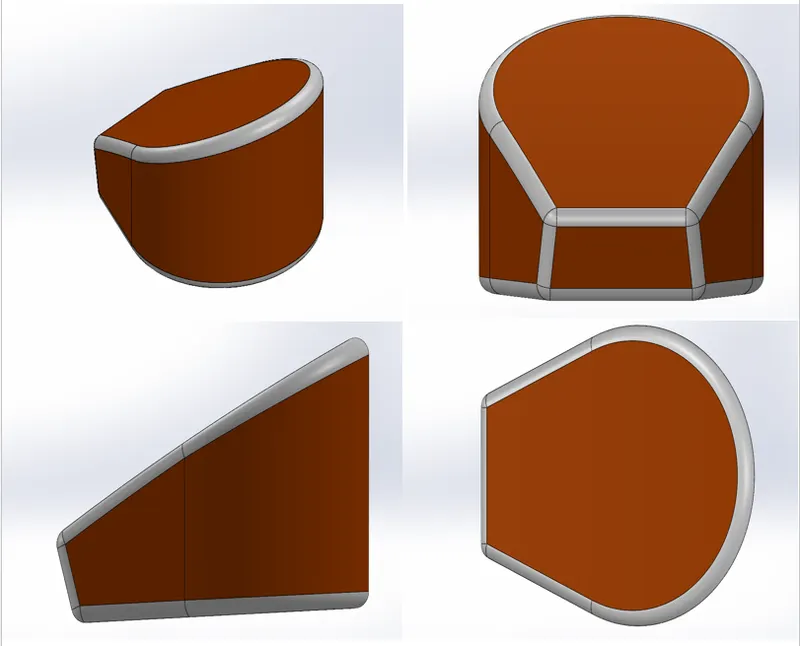
Oil tank is a component used to store the oil for lubrication and cooling purpose of the engine components. The tank is placed right below the rider seat on the top of the gear box. The base of the oil tank is sketched on the Top Plane and extruded boss above now to attain the structure of the oil tank one more sketch is made on the mid plane extruded and combined together and at last a shell function is used to make the part hollow and the edges are made round by applying fillet. Again the metal body is painted with the same sienna color and the filleted edges are given a white paint in the rendering process there is an application of decals which we will see further ahead.
all views of oil tank:
Tools Used
Sketch Tools:
- 3 Point Arc
- Line
Features:
- Combine
- Extruded base/ boss
- Shell
- Fillet
- Appearance
5. CHAIN
all views of chain
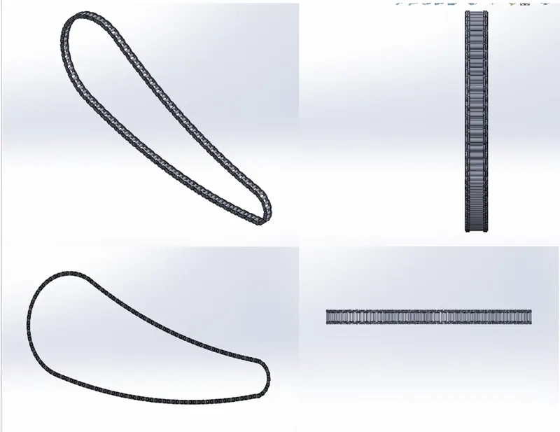
Chain is a set of several links made of small plates and pin joints, connected in a loop to make a power transmission component. This is mainly used for transmitting power from one shaft to another using sprockets. Now in this part we have first outlined the path of the chain with helps of arcs and lines then created the front and back link which we saved as a block diagram and then simultaneously applied with a concentric relation to one joint of the path then calculatedly we began with the process of curve path arrangement from on joint of the path to another determining the angles and the number of blocks required until the entire loop is completed. Finally after sorting out the arrangements we mirror the face of the links to the pins in the block diagram with respect to the mid plane. A fine finished chrome plate metal is used as the appearance of the linked part.
Tools Used
Sketch Tools:
- 3 Point Arc
- Centre Point Slot
- Circle
Features:
- Make and Save block
- Extruded base/ boss
- Mirror
- Fillet
- Curve driven pattern -tangent to curve
- Appearance
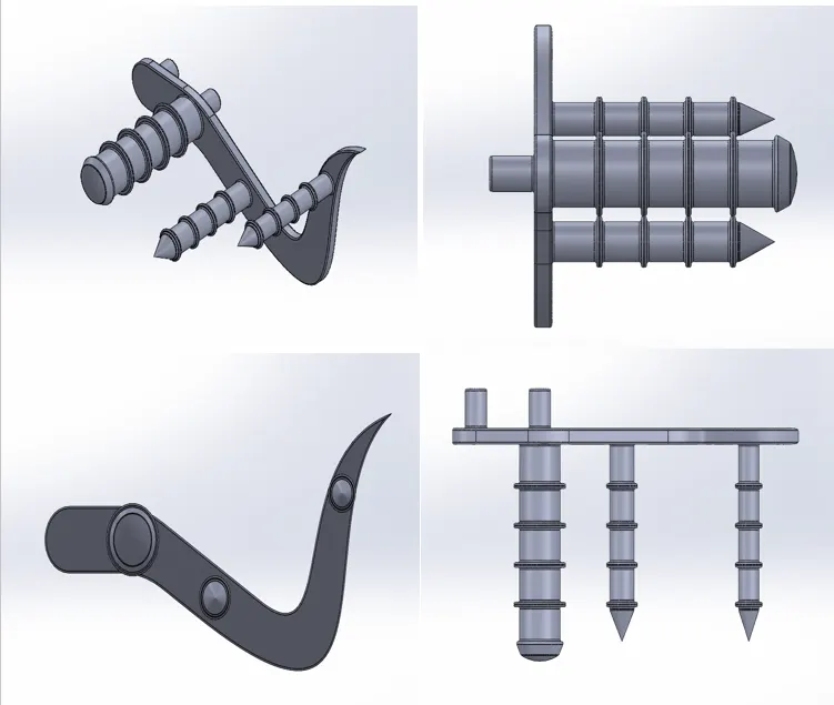
6. PEDAL
Pedal is a motorcycle component used by the rider to place his/her foot on it while riding the bike. It is mounted on both sides of chassis. In a chopper type motorcycle, the pedal are placed in forward position such that the legs of the rider are fully extended in a comfortable manner. The design starts with outlaying the sketch of the base of pedal on the front plane and an extruded boss is created with dimensioned circular holes for the foot rest and the pins which are extruded the second time. Now a sketch is created on the top plane for the foot rest which is then revolved to make an 3d image the top of the rest is applied with a dome and the edges and joints are filleted to avoid sharp cuts, the front and the rear extruded cylindrical parts are then chamfered to attain a proper finish and a circular pattern is extruded on each of the front facing extrudes which are then arranged using linear pattern. Fillet is applied to all the edges and the joints of the last pattern.
all views of pedal:
Tools Used
Sketch Tools:
- 3 Point Arc
- Spline
- Circle
- Line
- Sketch Fillet
Features:
- Revolve
- Extruded base/ boss
- Dome
- Fillet
- Chamfer
- Appearance
- Linear Pattern
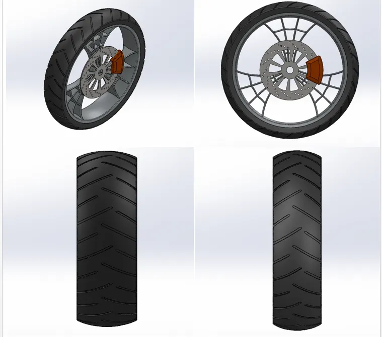
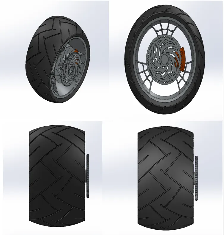
7. FRONT AND REAR WHEEL
Wheel consists of rim and tyre which make it the component that makes the connection between the motorcycle and the ground. The rim is an important strength component which ensures safe load carrying capacity of the bike. It should have enough compressive strength and able to absorb shocks and impacts. The tyres are the main contact surface to the ground. The wheel also houses a disc brake rotor and its caliper. The designing of both the wheels are similar the differences is in the size of the wheels. To begin a revolved part is created on the right plane which is the rim now the spokes are sketched on the right plane and extruded which is merged with the hub now to attain the spider web design on the spokes a sketch is made on the face of the spoke using the spline tool, converting entities and mirroring the part with proper references and construction geometries the sketch is then cut extruded. Then a circular pattern is made along the edge of the rim to make three forks. Now we design the disc or the hub of the wheel on the same plane offsetting it to a level and then extruding it now the designs are made on it and cut extrude is applied. The calipers are sketched on the face of the disk and extruded both sides which is then chamfered to attain the desired look and the edges are filleted. The sprocket is designed on the same plane and with an extruded cylindrical hub which is attained by revolving. The pattern is sketch on the face of the sprocket and cut extrude is applied which is then patterned in the entire sprocket, now the final sketch is made and revolved around are made using the revolve feature and on the inner face of handle bar we draw the geometry required for the levers and extrude them. The sharp edges are filleted and clutch we create a plane from which the other side of the fork is mirrored and all the parts are combined together to form the desired 3D shape.
all views of front wheel
all views of rear wheel:
Tools Used
Sketch Tools:
- 3 Point Arc
- Spline
- Circle
- Mid-Point Line
- Sketch Fillet
- Trim
- Extend
- 3 point Centre Rectangles
Features:
- Revolve
- Extruded base/ boss
- Extrude Cut
- Fillet
- Chamfer
- Appearance
- Circular Pattern
- Revolve Cut
8. FRONT FORK
all views of front fork:
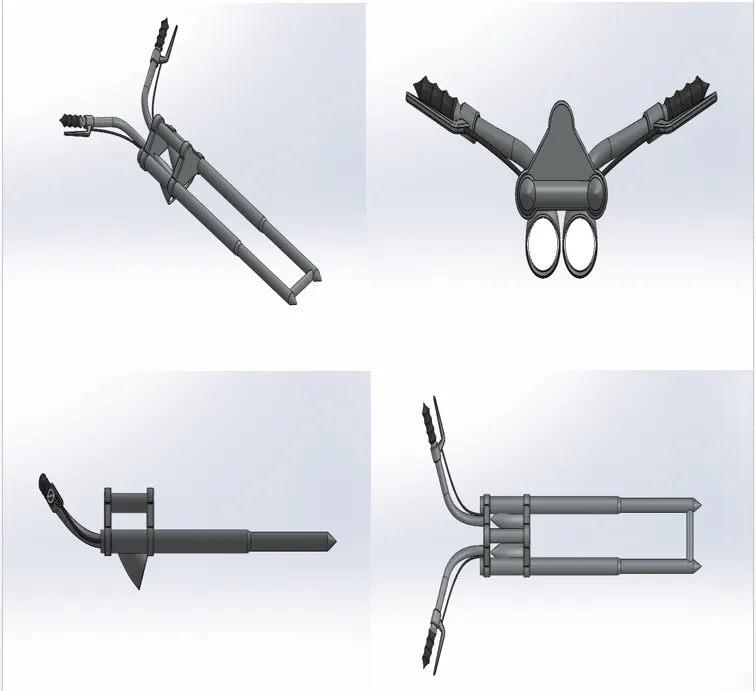
Front fork is a component that helps in maneuverability of the motorcycle. Its efficient design helps in better ride and handling of the motorcycle. It also houses various sub components such as headlights, handle bars, handle grips, triple clamps, brake lever, clutch lever etc. This part consists of front fork, handle bar, head lights, break and clutch levers, wires and handle grips. The idea to design the fork is to make one side of the fork or half the fork and then mirror it along the face and make cables and handle grips. The design is started with revolving a cylindrical fork along right plane then on the top of it the face is sketched and extruded which is mirrored and linearly patterned. Two cylindrical extrudes to join the upper deck and the mirror side of the fork. Another extruded part is curved along the top of the handle facing down which is the headlight. To make it hollow a part is extrude cut internal from the face of the headlight. The edges of the part is filleted to give it a headlight curved look. After all we focus on the handle which is sweeped using two curve used to form a projected curve and similarly on the front face of the sweeped area handle grips are made using the revolve feature and on the inner face of handle bar we draw the geometry required for the levers and extrude them the sharp edges are filleted and then comes another projected curve made to sweep the wires for the brake and clutch now we create a plane from which the other side of the fork is mirrored and all the parts are combined together to form the desired 3D shape.
Tools Used
Sketch Tools:
- 3 Point Arc
- Line
- Circle
- Sketch Fillet
- Trim
Features:
- Revolve
- Extruded base/ boss
- Extrude Cut
- Fillet
- Chamfer
- Appearance
- Linear Pattern
- Revolve Cut
- Chamfer
- Sweep
- Curve Projected
- Dome
- Body Move/ Copy
9. REAR FENDER
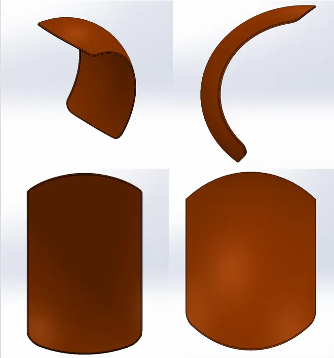
Rear Fender is an automobile part that is bound to the vehicle frame and is placed as a cover on the upper side of the tyres. It do the same function as front fender. The same method has been applied in the rear fender as it was in the front fender the only difference between the two are the sizes of both the fenders which vary accordingly with the size of the tire. Both the parts are metal and painted sienna which gives a bright orange texture.
all views of rear fender:
Tools Used
Sketch Tools:
- 3 Point Arc
- Line
- Spline
- Sketch Offset
Features:
- Revolve
- Split
- Shell
- Fillet
- Appearance
- Dynamic Mirror Entity
10. CHASSIS
all views of chassis
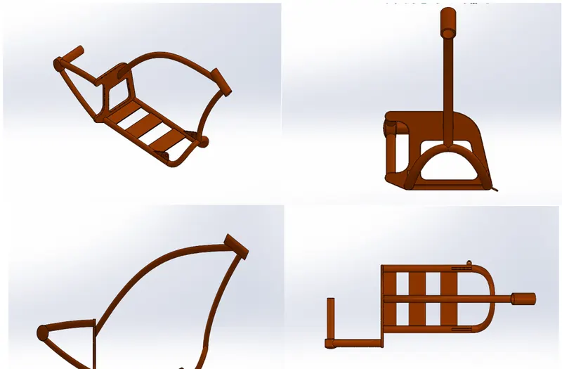
Chassis is the main strength component or structural frame work of any automobile. All the components of the motorcycle are either directly or indirectly or indirectly mounted to the chassis. Chassis should be made up of high strength material that can withstand variable compressive, tensile and shear stresses. The design of chassis begins with drawing two projected curve to attain the lower curved path of the block which is sweeped along the path which is then mirrored to attain the lower geometry. A sketch is made and extruded from the open end of the base and a block is created a part from the block is extruded out calculatedly to attain the desired shape and the base of the block is chamfered. The sharp edges are filleted both on the exterior and the interior two more sweeps are created and two more extruded geometry is made from the block to make the attachment required to join it with the sprocket, to make the upper rod of the chassis one more sweep is created from the front face of the block and the split tool is used to cut off the excessive materials, to join the chassis with the front fork a revolve part is created at the front and other the joints between the two sweeped rods is extruded. Now to make the attachments with the pedals and the kick stand two geometries are created extruded and the undesired part is extruded out. At the end all the sharp edges undergo desired fillet and a plane is added for the purpose of the further assembly purposes.
Tools Used
Sketch Tools:
- 3 Point Arc
- Line
- Circle
- Sketch Fillet
- Trim
Features:
- Revolve
- Extruded base/ boss
- Extrude Cut
- Fillet
- Chamfer
- Appearance
- Reference Geometry Planes
- Revolve Cut
- Chamfer
- Sweep
- Curve Projected
- Dome
11. ENGINE, MOTORS AND EXHAUST SYSTEMS
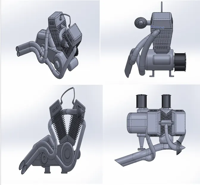
Engine is the main powerhouse of any of the automobile .Motorcycles are generally internal combustion engine spark ignition type. American Chopper has a V- Twin type engine consisting of external air filter, spark plugs for each cylinder, transmission pulleys, air cooling fins, starter motor, and front sprocket for chain drive, exhaust pipes and casing for sump and gear box. : a sketch is made on the front plane and extruded which is the design of the base of motor and several bosses are created along with the same sketch to attain a proper shape next the upper curved part. Now on the rear side of the motor two revolved features are made to make the arrangement for the transmission belt and the spokes are made using the extrude and linear pattern around the circular region and same process is used on the other side of the extrude too. The front of the cylindrical extrude is then cut out with the desired shape. The back of the motor the engine case and the top of the case is sketched and extruded one after the other and merged with the entire body a part from the engine body is cut out to make the fin which is linearly patterned throughout the surface. The fillets and chamfer are used . Now at the top a sketch is made and the spark plug is created with that the shape of the engine is now mirrored for the twin cylinder. Then the front gear is made for the chain link using extrude and cutting the edges of the 3D circular extrude as the design demands, and at the base of the engine hub the four stand are made for the assembly purposes a link is then sweeped between both the engines. Now comes the designing of the exhaust pipe from the engine to do that two projected curve is made both the curves are then joined together to form a composite curve which is sweeped all the way from the starting face of the engine to the back according to the dimensions the same process is carried out for the second pipe and at last the wires are attached to the spark plug with two different sweeps. The total appearance given to the engine is chrome plate metal.
all views of engine:
Tools Used
Sketch Tools:
- 3 Point Arc
- Line
- Circle
- Sketch Fillet
- Trim
- 3 Point Centre Rectangle
Features:
- Revolve
- Extruded base/ boss
- Extrude Cut
- Fillet
- Chamfer
- Appearance
- Reference Geometry Planes
- Revolve Cut
- Chamfer
- Sweep
- Curve Projected
- Dome
- Circular Pattern
- Linear Pattern
12. FUEL TANK
all views of fuel tank:
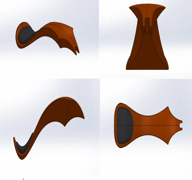
Fuel tank is the fuel storage component of the motorcycle. It is made to store flammable fluids or gas in a cool state away from the engine heat. Safety of the petrol is the main criteria in designing the fuel tank. Fuel tank of the American Chopper is made to house a seat and fit to the chassis centrally with the mount. It is made up of surfaces and finally these surfaces are knit together to form a complete solid body with hollow shell to store the fuel. To start off we must know all the features used in this come under the surface section of modeling, we begin by making an additional reference plane and draw two sketches on it which is surface sweeped to attain the basic layout of the gas tank. Now the edge is surface trimmed to attain the design of the tank one more plane is added and a surface loft is created as the front face of the tank now with the help of boundary sweep feature the front face and the side face are joined together with the rear of the gas tank. Mirroring the entire part and knitting them together we get the entire gas tank structure. At the rear end we make a seat by extruding the surface and filleting the edges of the seat to give a rounded off look now with surface loft and knitting tools we give a covering to the bottom of the gas tank, a sketch is drawn at the face of the gas tank to cut the u section for the assembly of the tank with the chassis and all the sharp ends are then filleted a shell is created at the end to make it hollow. Again the base sienna color has been applied to the part and a grey cotton material is used for the seat the decals are used which will be discussed under rendering the part.
Tools Used
Sketch Tools:
- Sketch Picture
- Line
- Circle
- Sketch Fillet
- Trim
- Spline
Features:
- Revolve
- Extruded base/ boss
- Extrude Cut
- Fillet
- Chamfer
- Appearance
- Reference Geometry Planes
- Revolve Cut
- Chamfer
- Sweep
- Curve Projected
- Shell
ASSEMBLY
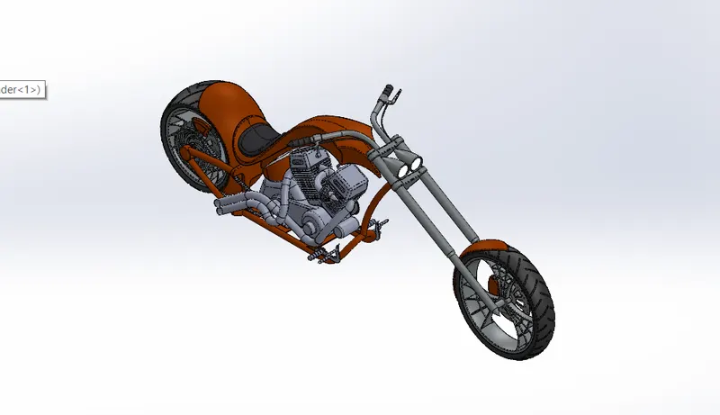
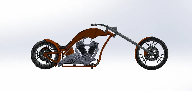
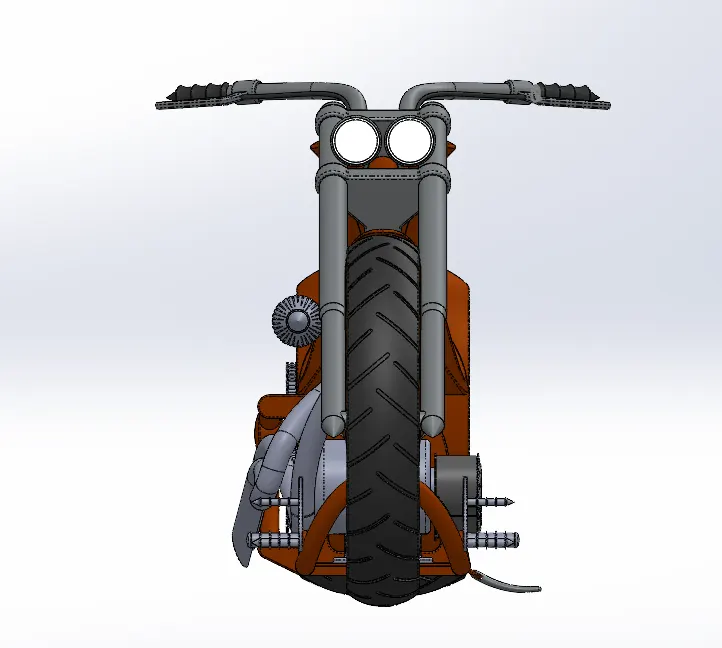
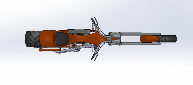
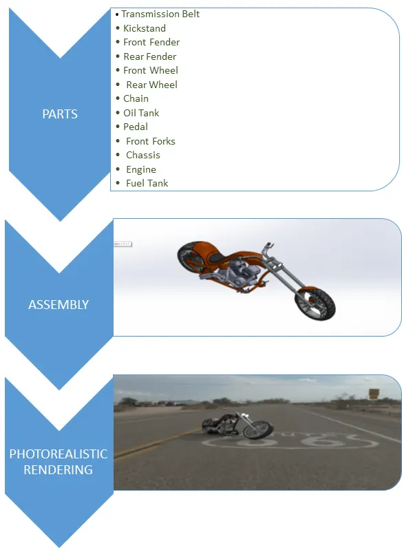
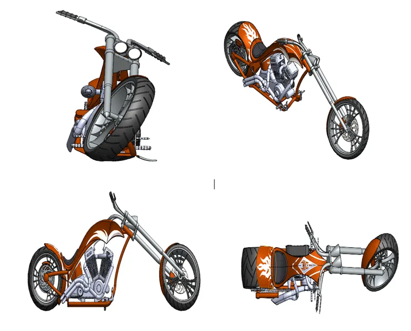
After making all the parts the most important part of assembling the entire chopper to a single file begins. To start we begin by bringing in the chassis first and using its plane and geometry as a base for the entire solid assembly, the second part we bring in is the engine the base stand of the engine is matted coincident with the base of the chassis then the planes of the engines are mated so it is a fixed body and doesn’t move at last a distance mate is applied so that the part is fully defined. After that we bring in the pedal the pedal has the pins which are mated with the holes in the chassis and a coincident mate is formed to make the part fixed. Now as we need pedal on both the sides the same pedal is then mirrored on the other side of the chassis with defining the properties of the opposite side. we bring in the kick stand here he first mate made is a concentric with the hole created in the chassis and the extruded part in the stand the to define the angular rotation of the kick stand an angular mate is provided with the body so that there is no disturbance with model. Now we bring the transmission belt which is mated on the engine drivers to fully define this with the mates we provide an angle to make the joint coincident with the drivers, next we bring in the oil tank which is directly placed and matted above the engine, comes in the rear wheel which is concentrically matted with the chassis and the hub of the wheel the planes are mated accordingly and a parallel mate is applied to fully define the sketch. The rear fender is now applied above the rear wheel, now the chain link is brought on to start a width mate between the chain link parts and the sprockets of the rear wheel and the engine, now the gas tank is fixed with a distance mate and a parallel mate with respect to the chassis, the front fork is mated coincidently with the upper part of the chassis and a width mate is applied to retain the vertical motion of the fork. For the turning angle of the front part of the chopper an angle mate with certain limitations is applied with the fork and the chassis, finally the front wheel is attached with the front fork as it was attached in case of the rear wheel and the fender is placed above the front wheel as shown in the diagram.
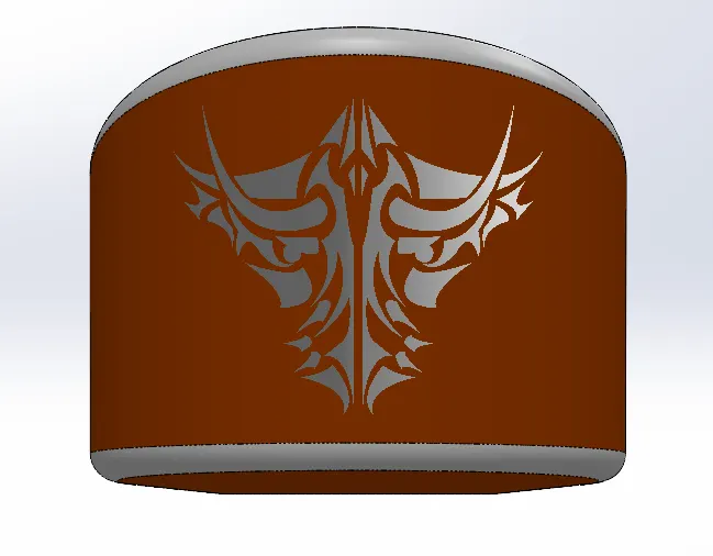
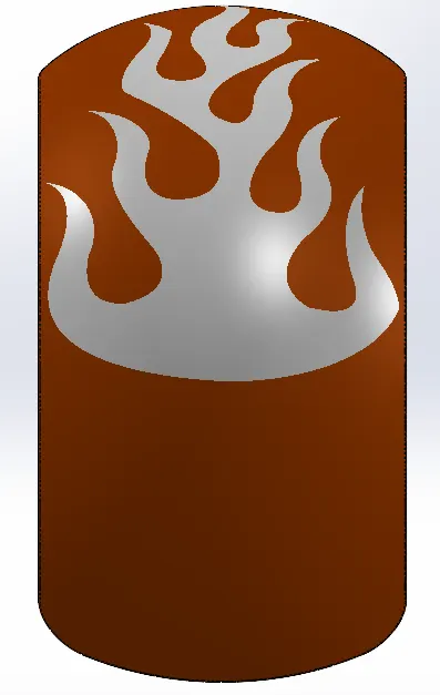
Decal adding to Individual Models:
1. Decal on Gas Tank :
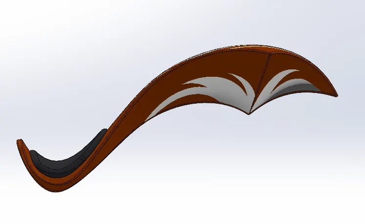
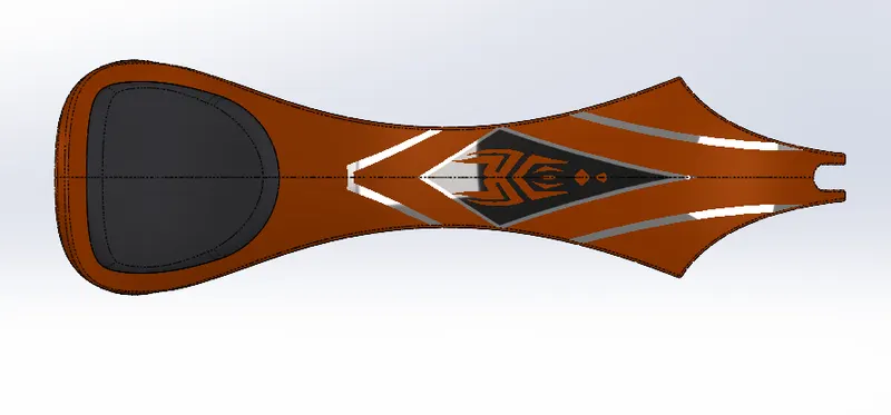
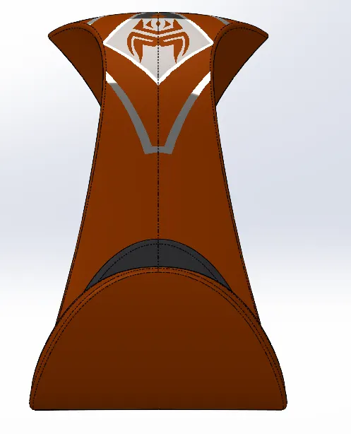
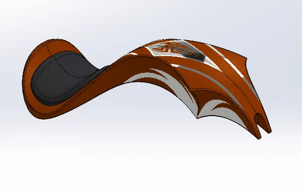
2. Decal on Oil Tank :
3. Decal on Rear Fender:
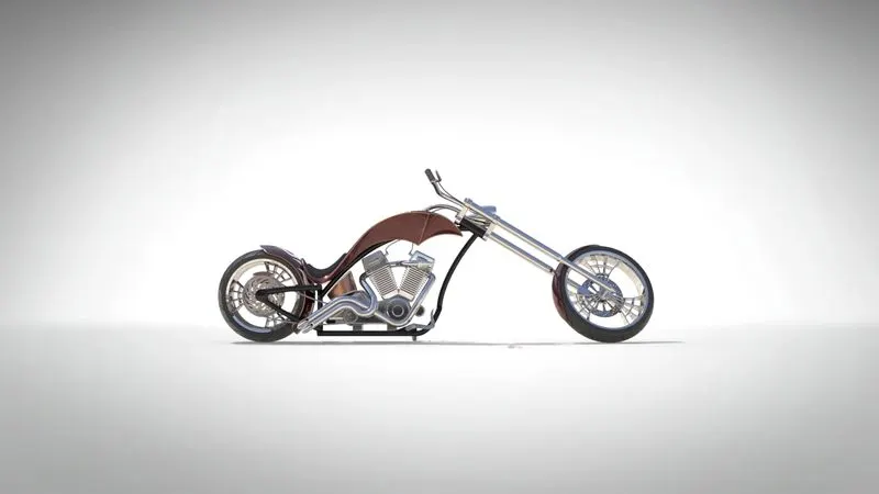
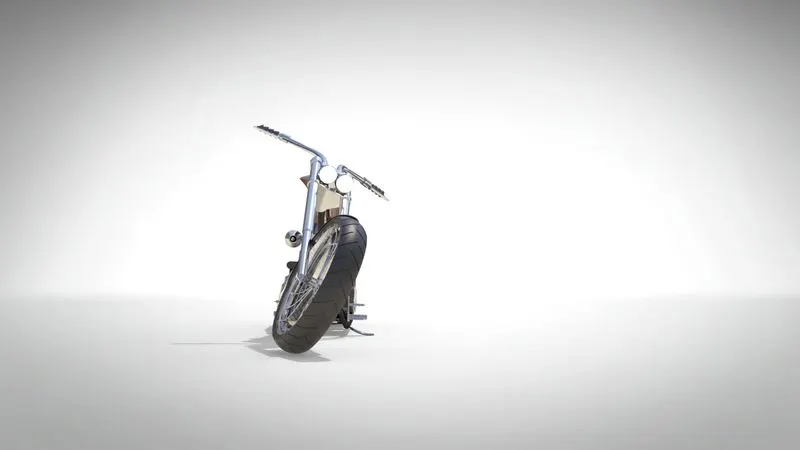
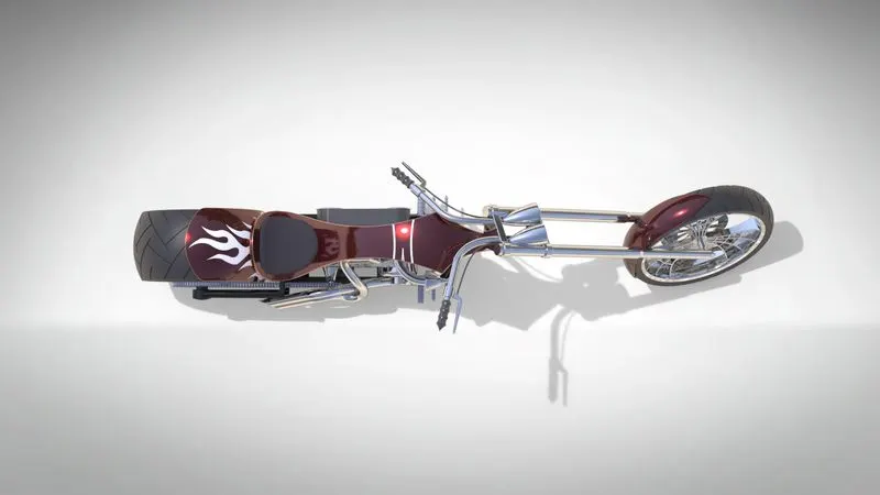
Assembly of Chopper With Decals
PHOTOREALISTIC RENDERING
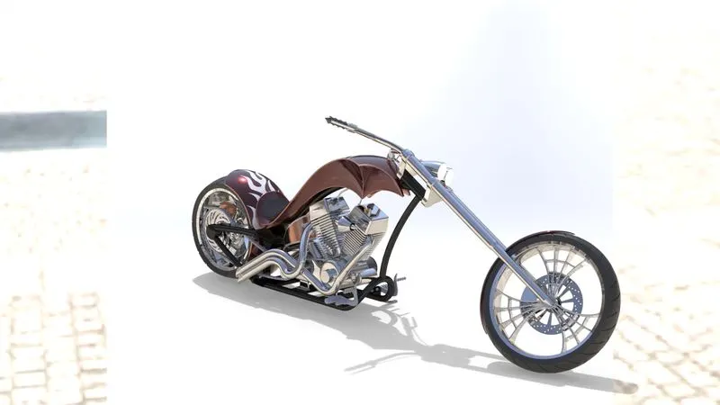
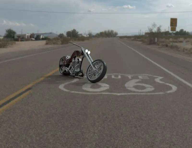
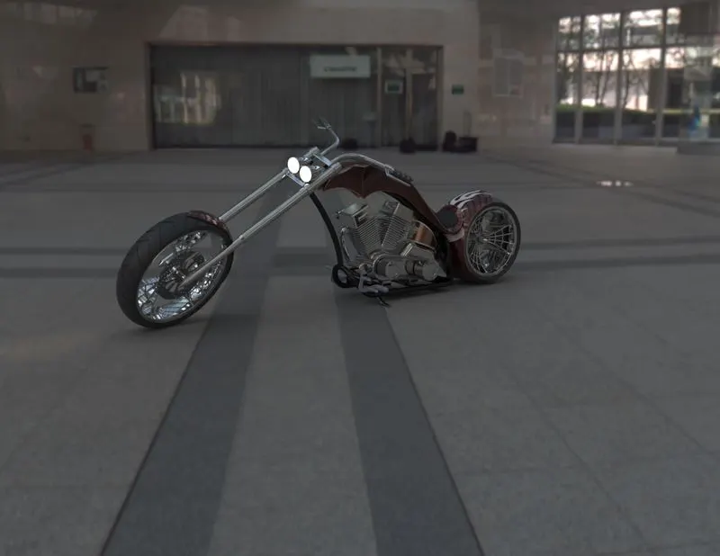
Rendering of the assembly is done to make good quality 2D images for the purpose of advertising and promotion of the products before selling it to the customers. Photorealistic rendering creates high quality images or motion graphics if available so as to look appealing in various environments and backdrops. The final step of the bike to make it look realistic as we have already discuss the uses of rendering a model here we try to make it look as realistic as it was possible we started off with checking the appearance added on all the parts then we to make it look more stylish we add some decals on the rear fender and the face of the oil tank. We try to make it more realistic by giving it a camera view setting the desired lights and the focal distance creating the angle of the view and saving the camera angle which gave a realistic view to the chopper. Now we take our assembly file into solid works visualize where we start making the product more and more realistic with adding the background changing the and adjusting the brightness, shadow density and gamma levels according to the different requirements of the different backgrounds changing the color of the model and checking what suits the best with which background until we get the desired and astonishing product ready.
CONCLUSION
Design, Assembly and Photorealistic Rendering using Solidworks was successfully Completed.