Radar Mast & Final Assembly of Yacht
SKILL-LYNC
PROJECT REPORT
M0DELLING OF YACHT
ON SOLIDWORKS
By
K.SANDEEP
INTRODUCTION
The designing and modelling of different parts of Yacht and assembling them to get a complete model of the Yacht was explained in this project by using Solidworks. It also contains Rendering of the model using Solidworks Visualize to make the Yacht more natural, eye-sighted and realistic.
MODELING AND ASSEMBLING FEATURES
The below discussed modelling features are used for modelling The Yacht.
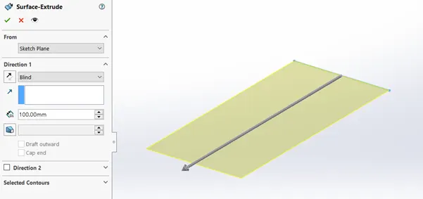
- EXTRUDED SURFACE:
This feature converts a 2D sketch into surface with respect to its dimensions in the normal direction. First, we need to draw a fully defined 2D sketch and then extrude the sketch with the direction and contours.
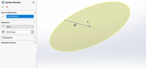
- REVOLVEED SURFACE:
This feature is used to revolve a 2D sketch along an axis or centerline and makes a surface. A 2D sketch is drawn and revolved by selecting a line as a reference for axis of rotation and defining the angle of rotation.
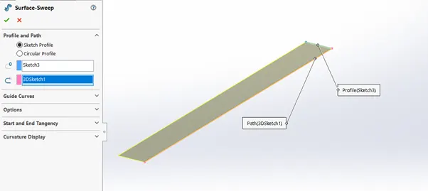
- SWEPT SURFACE:
This feature is used to sweep a 2D sketch along any path to make a surface. For this feature 2D sketch and a path is required.
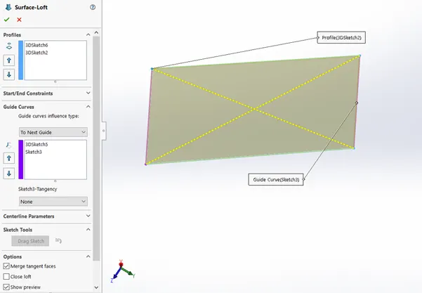
- LOFTED SURFACE:
This feature is used to loft a 2D sketch into a surface with the help of guide curves. For this feature two sketch profiles and a guide curve.
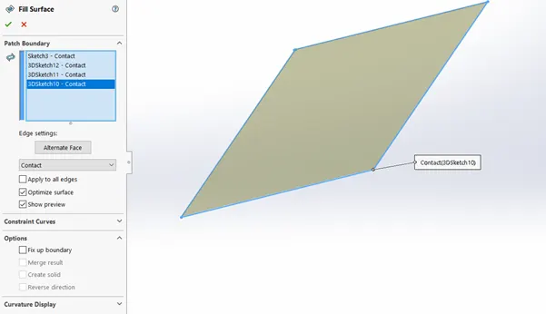
- FILLED SURFACE:
This feature is used to fill the 2D sketches to make a surface. For this feature we need a closed and a fully defined sketch, we need to select the for boundaries of the sketches.
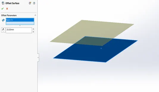
- OFFSET SURFACE:
This feature is used to offset the surface with respect to direction and dimensions. For this we need to select the surface then offset the surface with the direction and dimensions.
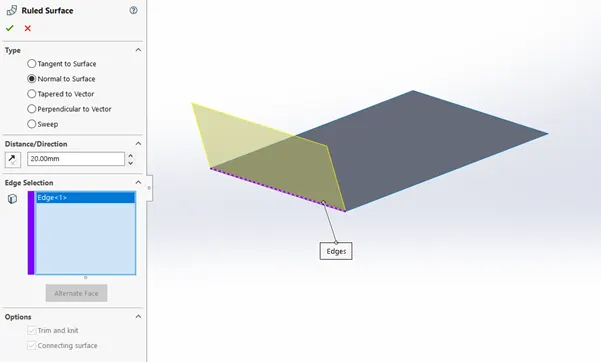
- RULED SURFACE:
This feature is used to extrude any edge of the surface with the distance and dimensions. We can make ruled surfaces with five types. They are, Tangent to surface, Normal to surface, Tapered to vector, Perpendicular to vector, Sweep. We need to selected an edge of the surface with the type of ruled surface then make a ruled surface with the direction and dimensions.
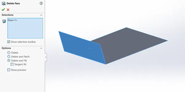
- DELETE FACE:
This feature is used to delete the face of any knitted surface. For this feature we need to select the face and delete the face of the surface.
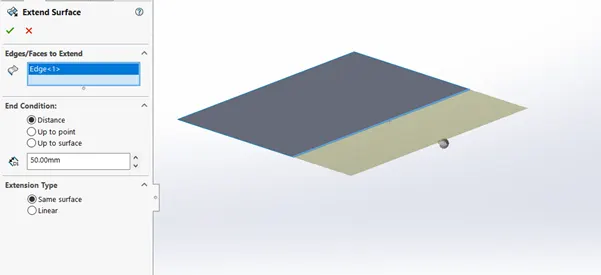
- EXTEND SURFACE:
This feature helps to extend any edge or face of the surface with the end conditions. We have to select the edge or face to extend with the end condition as distance or up to point or up to surface.
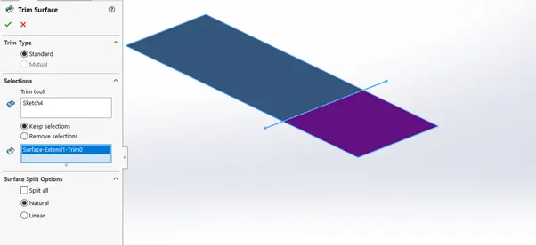
- TRIM SURFACE:
This feature is used to cut the surfaces. For this command we need to draw a reference line as the trim tool. After cutting the body, we can keep or remove the cut surface by selecting the keep or remove selections.
- KNIT SURFACE:
This feature is used to make multiple attached surfaces into a single surface. For this feature we need to select the surfaces with controlling the gap between them and merge them.
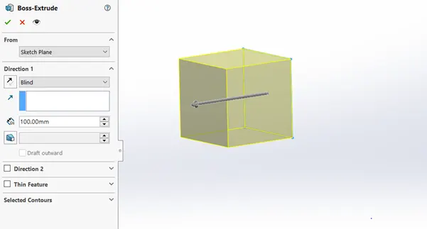
- EXTRUDE BOSS/BASE:
This feature converts a 2D sketch in to a 3D model with respect to its dimensions in the normal direction. First, we need to draw a fully defined closed 2D sketch and then extrude the sketch with the direction and contours.
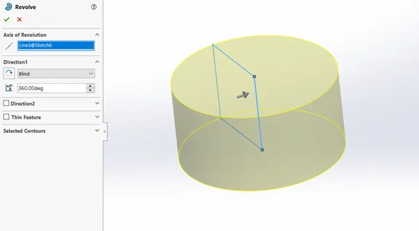
- ROVOLVED BOSS/BASE:
This feature is used to revolve a 2D sketch along an axis or centerline and makes it a 3D model. A 2D sketch is drawn and revolved by selecting a line as a reference for axis of rotation and defining the angle of rotation.
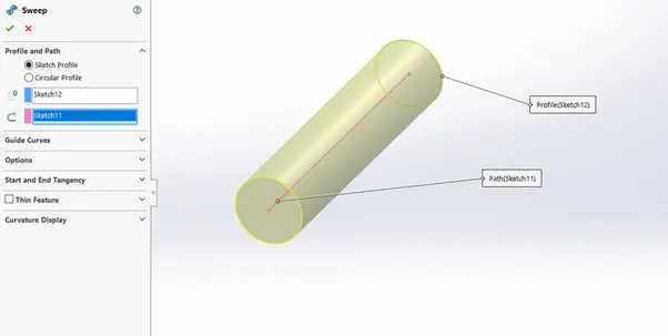
- SWEPT BOSS/BASE:
This feature is used to sweep a closed 2D sketch along any path. For this feature a closed loop and a path are required.
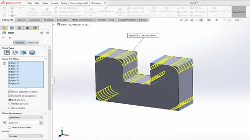
- FILLET:
Fillet is a very handy tool, it is used to round the edge, vertex or face on both inside and outside of a 2D or 3D model. Fillet is defined by type, location and radius.
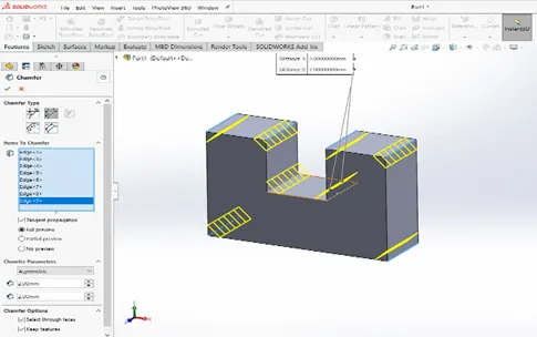
- CHAMFER:
This feature is used to remove a sharp edge by creating sloped edge, vertex or face. Distance and angle of the chamfer are defined.
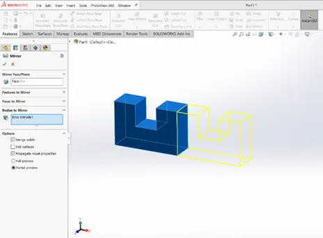
- MIRROR:
This tool is used copy a 2D sketch or a 3D object about a reference line or sketch.
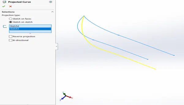
- PROJECTED CURVES:
A projected curve is a 3D curve which is a resultant of two sketches on intersecting planes.
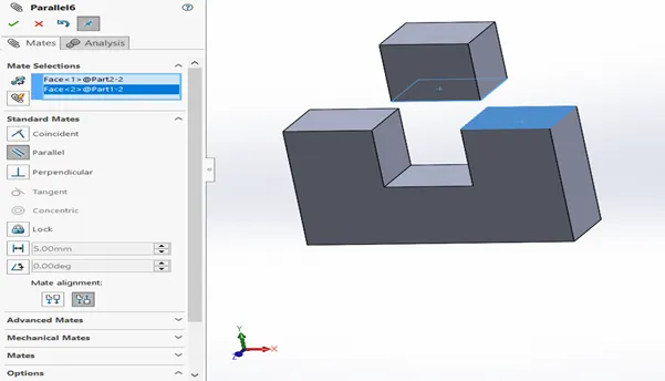
- MATES:
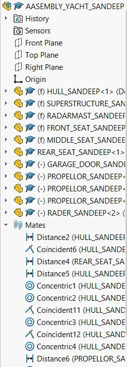
Mate operation is the basic tool for assembling the parts. There are various mate operations such as coincident, parallel, perpendicular, tangent, concentric, lock, etc. We can mate two faces by defining distance or angle between them.
- DOME:
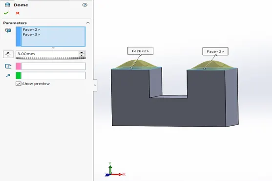
Dome feature is used to expand or remove the face of the model into arc structure. We can create one or more dome features on the same model. Set the value for which the dome expands. Click the direction vector and select the direction. Specify the elliptical dome foe the cylindrical and conical models.
- SHELL:
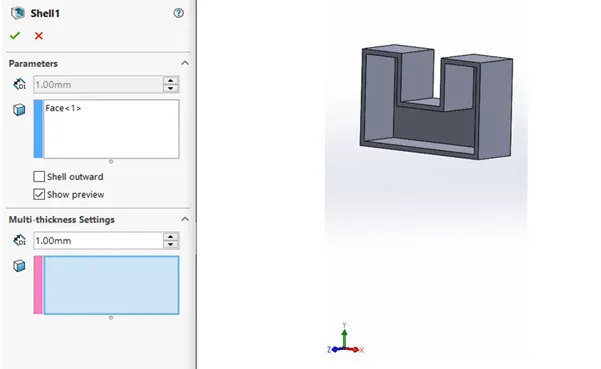
shell tool is mainly used for shelling process, in which the material removed from the inner body of model by keeping small thickness and results a hollow model. Using this tool, you can make either completely closed hollowed model or one face opened type.
- COMBINE:
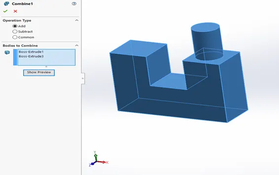
This feature has 3 operations. They are, Add, Subtract and common. Add operation is used to combine the solid bodies. Subtract operation is used to remove a solid body from another solid body. Finally common operation is used to keep the common part of the solid bodies.
- SPLIT:
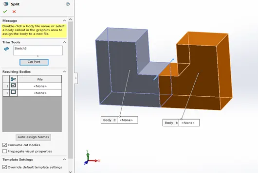
Split tool is used to cut the bodies. For this command we need to draw a reference line as the trim tool. After cutting the part, we can keep or remove cut bodies by selecting consume cut bodies.
- LINEAR & CIRCULAR PATTERN:
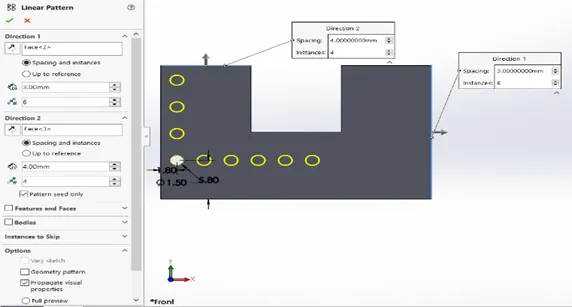
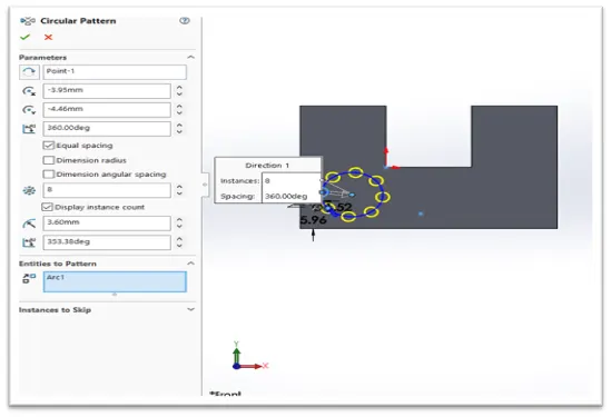
The Linear Pattern Command is used to drive features, faces, or bodies in a linear direction. The Circular Pattern Command is an excellent tool used to replicate features, faces, or bodies in a rotational manner about an axis.
DESIGN APPROACH
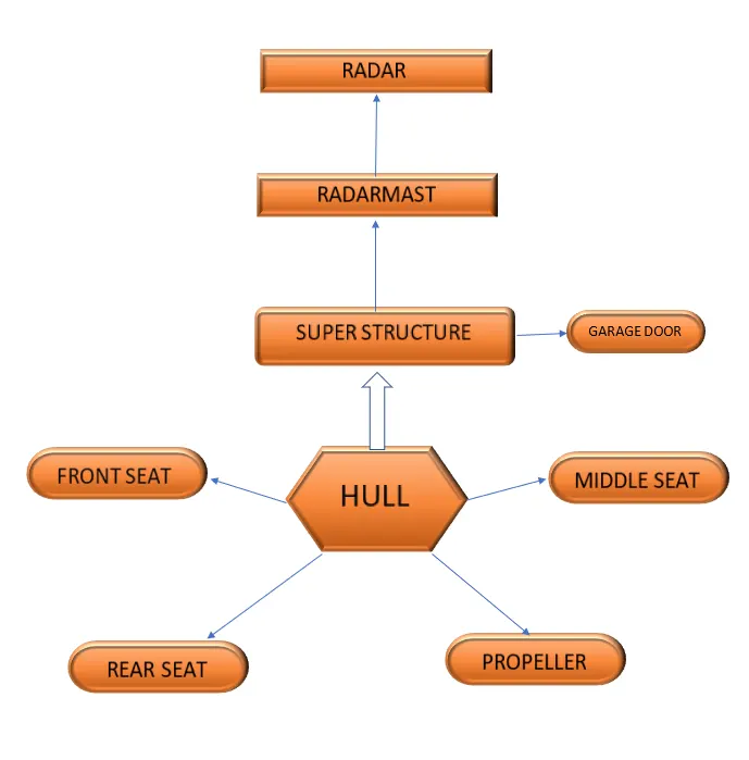
MODELLING
- HULL:
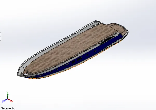
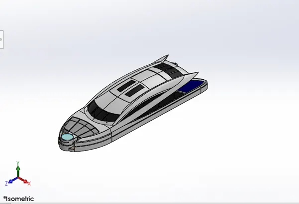
A Hull is the watertight body of a ship or boat. Top of the deck may be a deckhouse and other superstructures such as mast. The line where the hull meets the water surface is called the waterline. It was modelled by using the surface modelling features. Finally, appearance was given to the hull.
- SUPERSTRUCTURE:
A Superstructure is an extended construction of any platform that rises from the rest of platform. The word comes from a combination of two Latin words, the Latin prefix ‘super’ means in addition or above or in excess of, where as the stem word ‘structure’ means to build or to heat up. The superstructure means to add a construction to an already existing structure.
- PROPELLER:
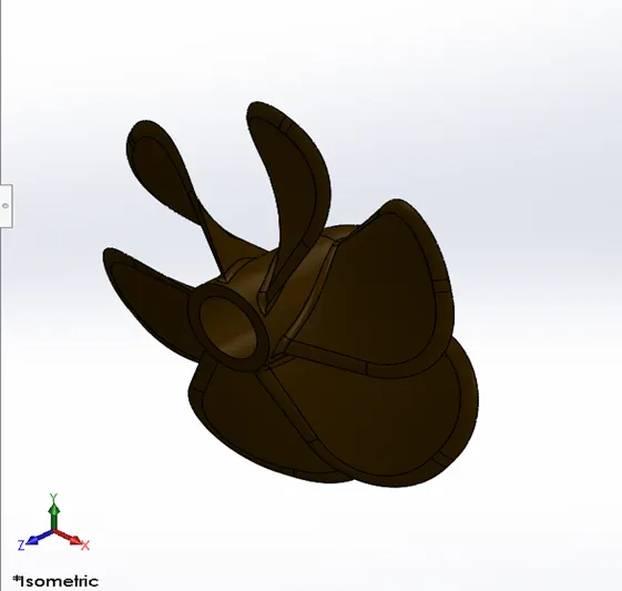
A propeller is a device with a rotating hub and radiating blades that are set at a pitch to form a helical spiral, that, when rotated, performs an action which is similar to Archimedes' screw. It transforms rotational power into linear thrust by acting upon a working fluid, such as water or air. The rotational motion of the blades is converted into thrust by creating a pressure difference between the two surfaces.
- RADAR:
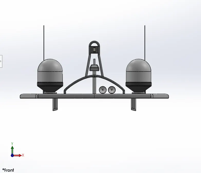
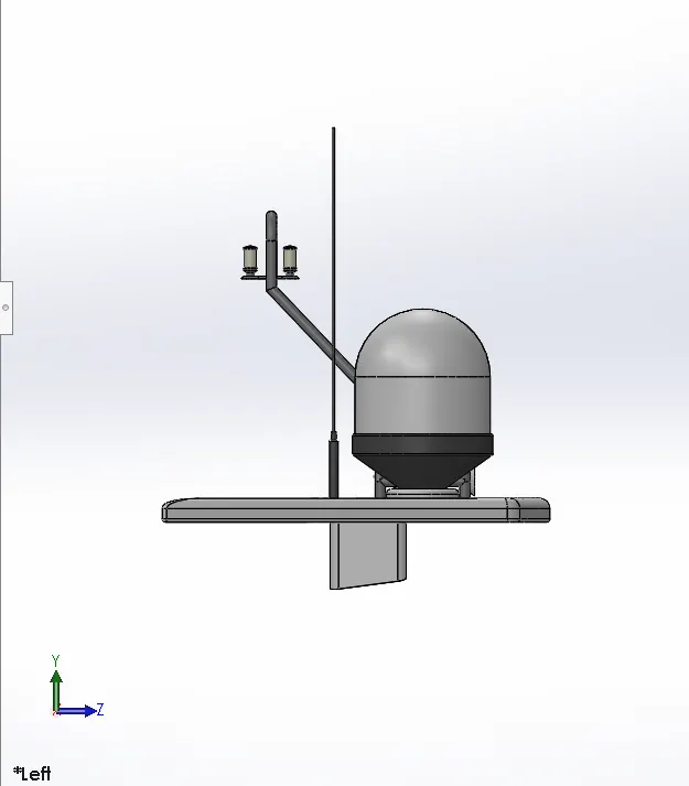
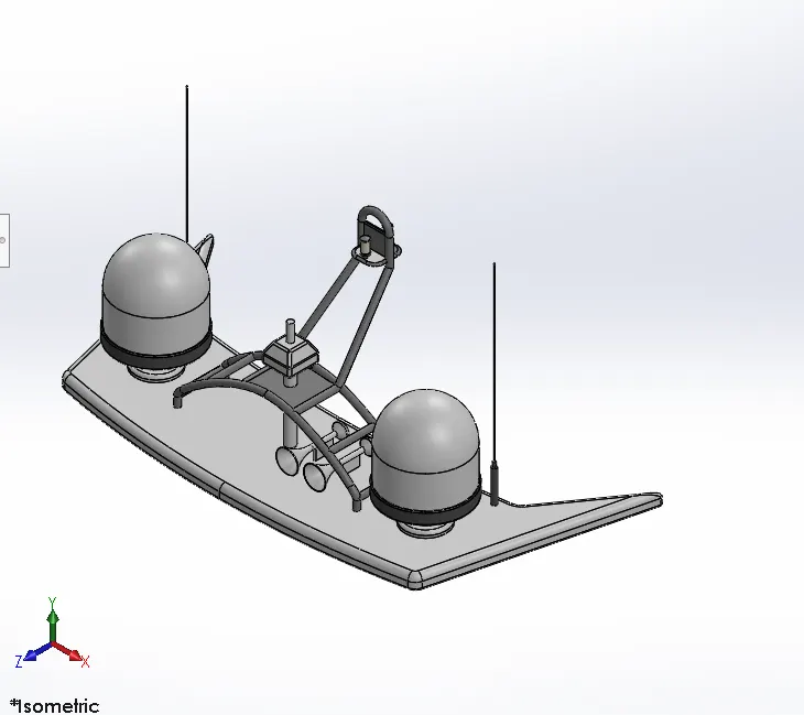
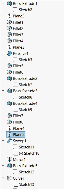
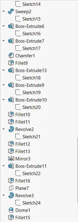
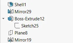
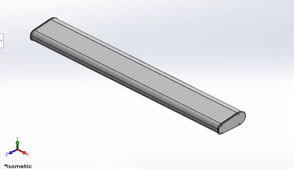
Radar is a device used for detecting objects. It is a very important device in any yacht/ship. It is mated with a part called radar mast and placed on the topmost part of the yacht. It is modelled only in solid modelling. it is a symmetric model so the other half is mirrored.
- RADARMAST:
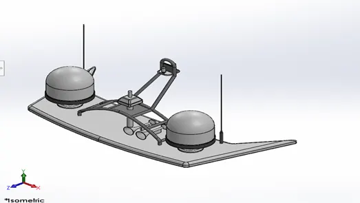
Radar is a device used for detecting objects. It is a very important device in any yacht/ship. It is mated with a part called radar mast and placed on the topmost part of the yacht. It is modelled only in solid modelling. it is a symmetric model so the other half is mirrored.
- GARAGE DOOR:
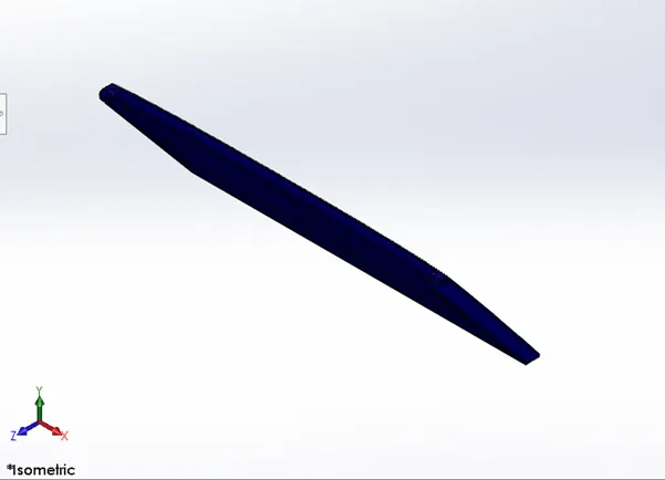
Garage door is main door of the luggage room of hull.
Where we can put any thing like car, bike etc.
- FRONT SEAT:
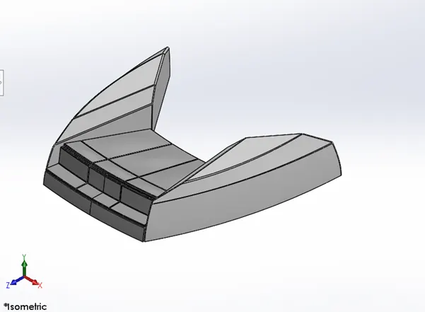
This seat is situated on hull and front of the structure. It is used to seat and take rest for those persons who is presence of yacht.
- MIDDLE SEAT:
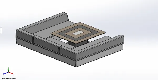
This seat is situated on hull and just backoff superstructure. People can also drink and take food by sitting on it by using a table in front of it.
- REAR SEAT:
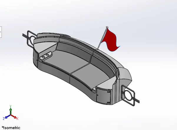
This seat is situated on back of hull and near to the middle seat.
ASSEMBLY OF YACHT
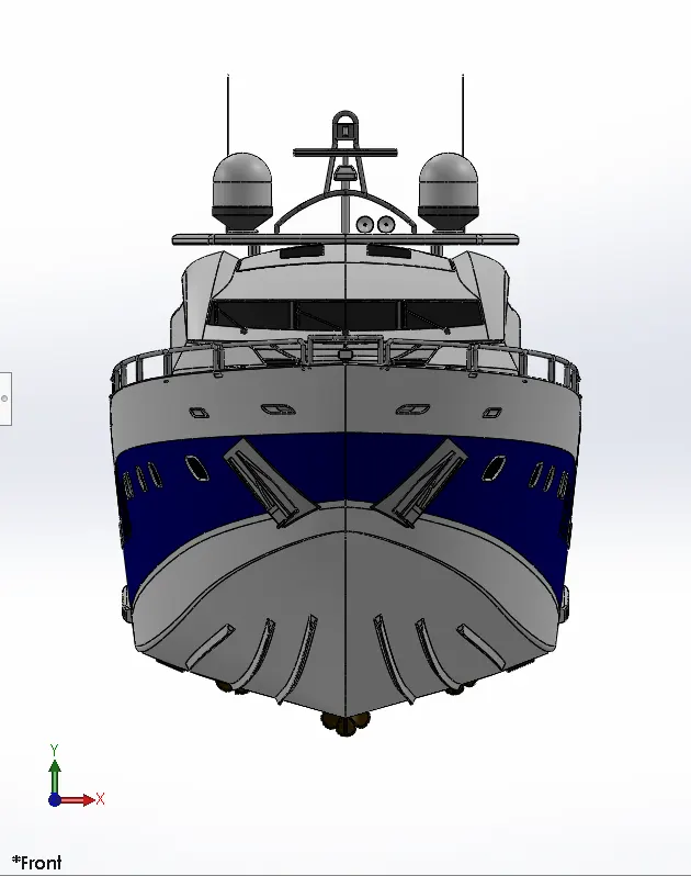
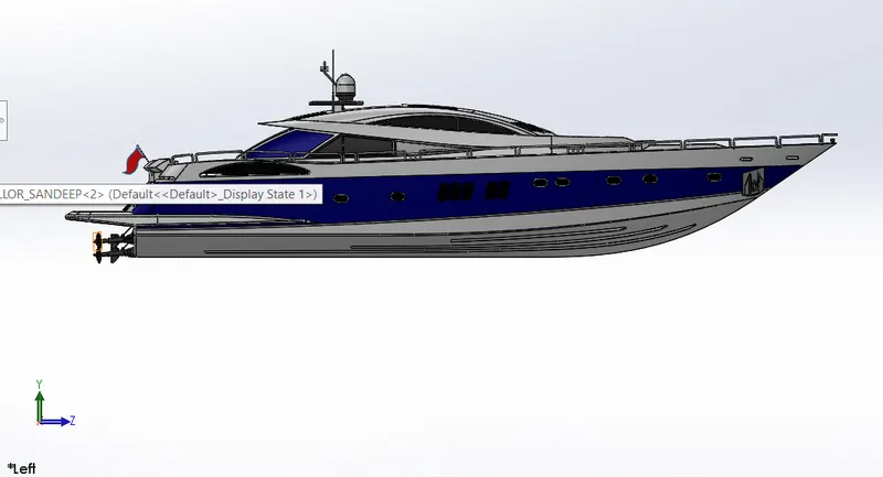
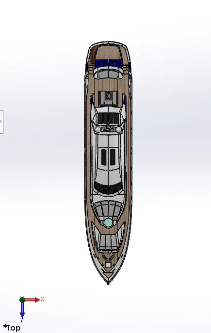
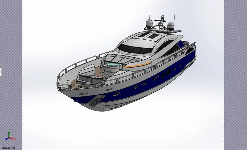
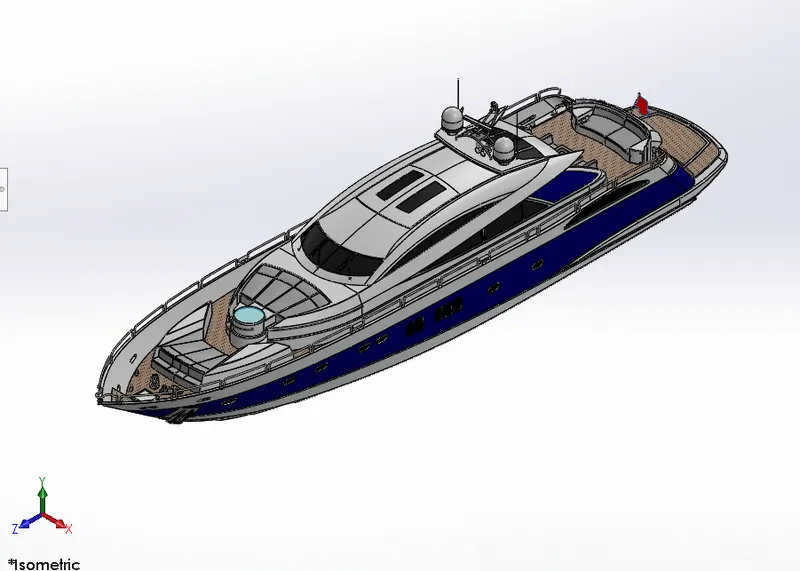
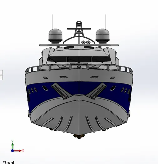
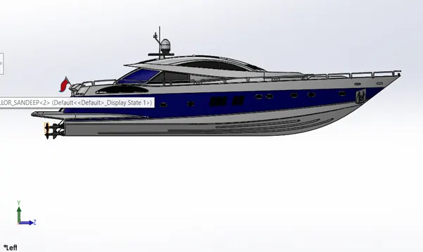
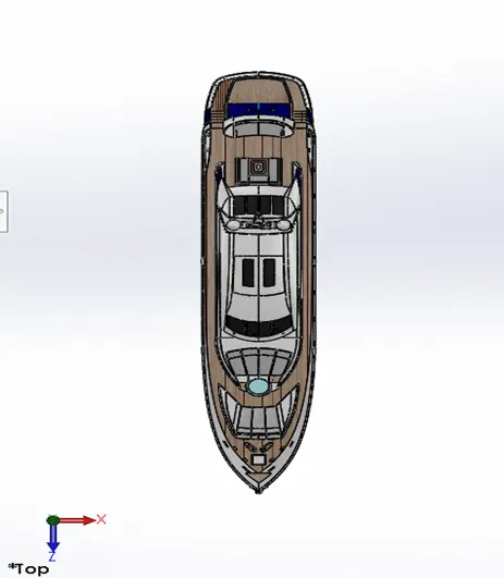
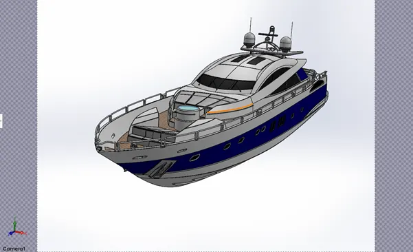
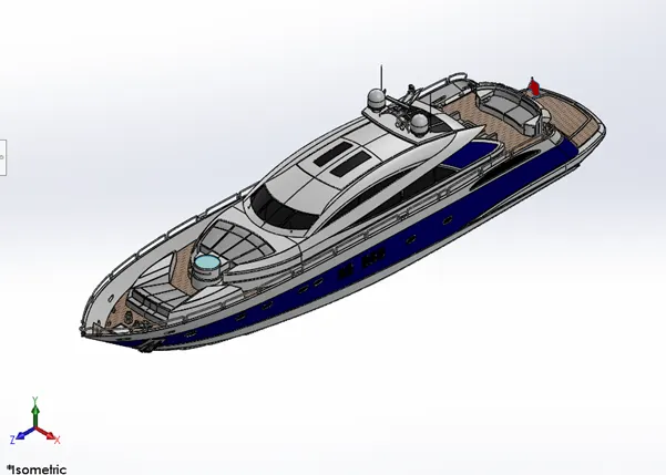
All the parts modelled were imported to assemble them. In assembly, mate feature was often used to locate and relate the parts with one another. Hull was inserted initially and fixed. The other components were inserted and related to the Hull.
RENDERING OF YACHT
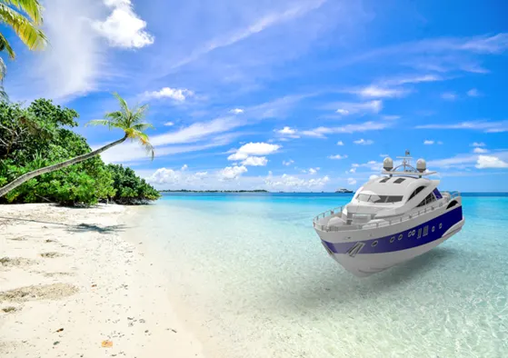
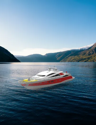
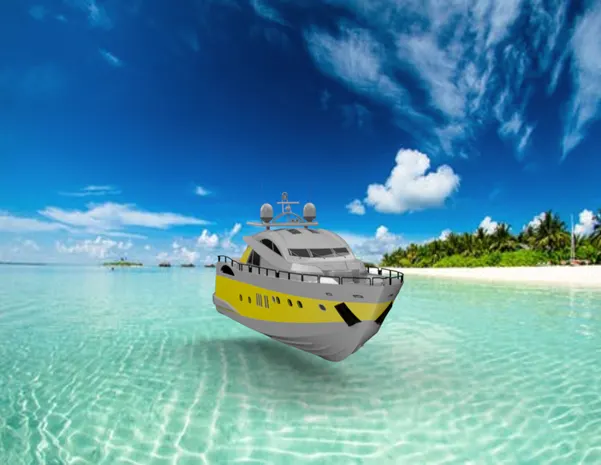
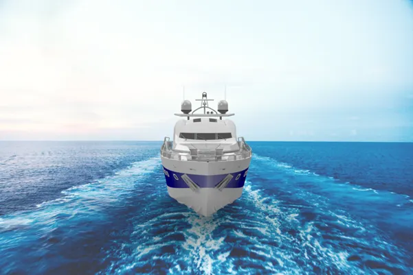
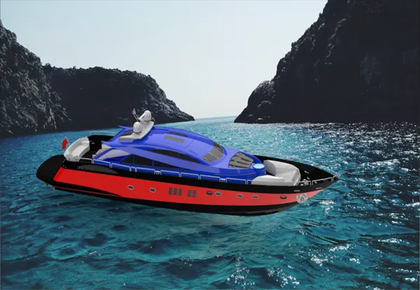
In rendering, The Yacht was made to set up in such a way to look natural and unique. Decals were added to the body parts. Views and light directions were changed. Using Solidworks visualize, the appearances, background scenes and camera views were changed. Then final rendering was done to make the Yacht, a cool and realistic one.
CONCLUSION:
- The parts of the Yacht are modelled using Solidworks.
- The parts are assembled using assembly module of Solidworks.
- The realistic image was rendered with the use of Photo view 360 and Solidworks visualize.