Week 8 - Challenge 1 - Draft Analysis on a Fan Cover
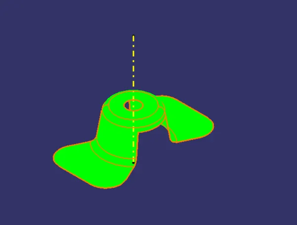
TOOLING AXIS AND DRAFT ANALYSIS ON A GIVEN CLASS-A SURFACE - FAN COVER
TOOLING AXIS: The direction in which the mold or core and cavity opens is the tooling axis.
PROCEDURE FOR CREATING TOOLING AXIS
- Connectivity of class-A surface: checking the connectivity of the surface, this can be done by creating boundaries or simply using the join option such that any openings can be easily visualized.
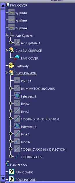
- By using the boundary option, the boundary of the hole was created and the center point was marked.
- Then the dummy tooling axis was created with the center point in the z-direction.
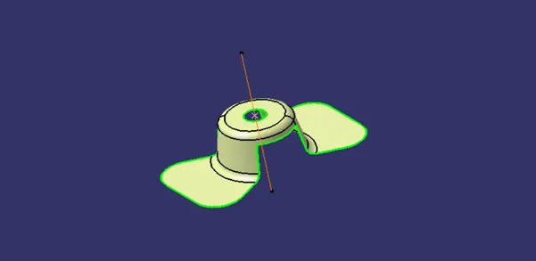
- By using the axis system the intersection curves were created over the xz plane and then the sides were extended by using point to point line then by using bisecting lines the tooling axis in X direction was created.
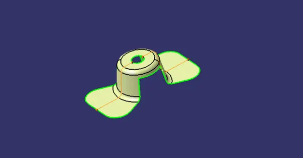
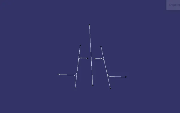
- Then by using zy plane the intersection curves were created as shown below and the same procedure was followed for creating the tooling axis in the Y direction.
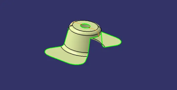
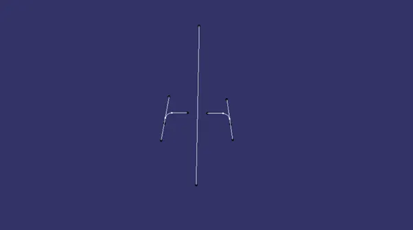
- Finally, by using the bisecting line option the tooling axis were creating by selecting the tooling axing x direction and y axis direction.
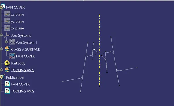
PUBLICATIONS:
The tooling axis and the class-A surface published for further easy reference, from Tools-Publications.
DRAFT ANALYSIS:
If the part is having a straight 90-degree profile from its base surface then the part cannot be ejected from the tool. A small draft angle is provided to each and every area of the component in order to get an easy removal of the component from the tool. Here the part should get easily removed from the panel dies or mold. Here we are providing the direction in which the component should eject in order to get an easy removal of the components from the tool.
Factors to be considered while doing the draft analysis
The major consideration of draft analysis is whether sufficient draft angle is provided on the component.
Components while designing should be provided with a considerable amount of the draft angle depending on the manufacturing consideration. For plastic components we provide a draft angle of 3-degree.
Draft angle of 0.5 is given to the rib feature on the plastic parts.
PROCEDURE TO PERFORM A DRAFT ANALYSIS
- Create a tooling axis using bisecting lines from line command.
- Draft analysis options are available inside the following work benches: part Design, Generative Shape Design, Wire frame and Surface for Building, Freestyle shaper.
- Insert>Analysis>Draft Analysis.
- Draft Analysis dialog box with color scale appears on the screen. So, the first mode option is the quick analysis mode and the second is full analysis mode. Here the quick analysis mode is used.
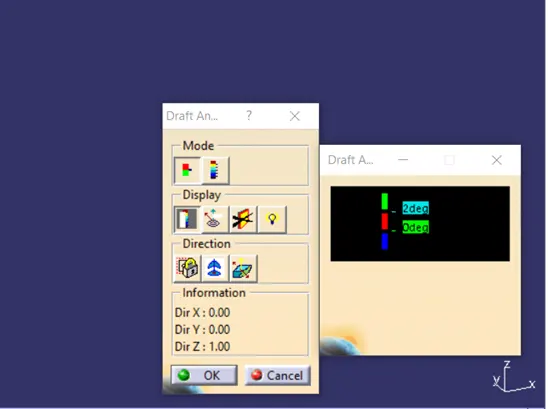
- Draft analysis was carried out by pulling the compass to the tooling axis and an inverse draft axis was carried out if required.
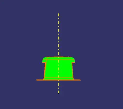
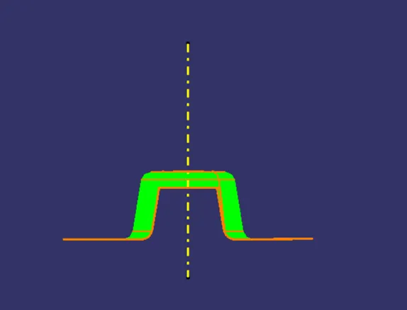
- If the surface was in green then the model passes or else further operations need to be carried out.
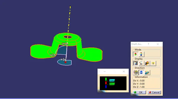
- By using the analysis under the running point complicated parts and surface were checked in detail.
- Try zoom in and check if each and every region of the panel is showing green, if in some region, red or blue is showing instead of green, those negative regions are below 7-degree and have no draft applied on those regions. Those blue and red negative regions need to be changed.
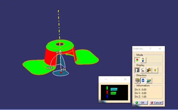
- Thus, the draft analysis for fan cover was carried out by creating the perfect tooling direction and the given class-A surface was ready to move on for further operations.